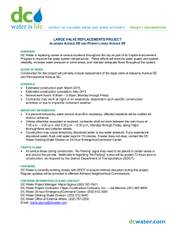
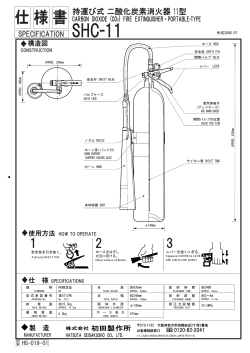
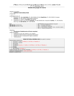
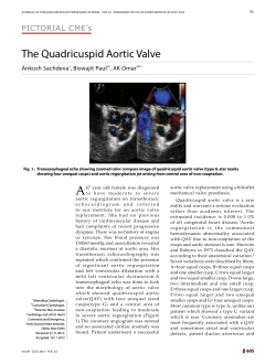
Bulletin No. AY-710-A GP-11 Pressure Reducing Valve Integral Mount Pilot Installation, Operation & Maintenance Instructions Typical Single Stage Reduction Installation (For Steam) Minimum of 20 Outlet Pipe Diameters to First Turn or Valve Minimum 10 Inlet Pipe Diameters Control Pipe (Pitch Down) Gate Valve Safety Valve Armstrong Strainer Globe Valve GP-11 By-pass Minimum of 10 Pipe Diameters From Last Valve or Fitting Armstrong Trap Figure 1-1 This bulletin should be used by experienced personnel as a guide to the installation of the Model GP-11 Pressure Reducing Valve. Selection or installation of equipment should always be accompanied by competent technical assistance. You are encouraged to contact Armstrong International, Inc. or its local sales representative for additional information. Installation Instructions 1. An Armstrong Inverted Bucket Steam Trap is recommended to drain the condensate at the inlet of the PRV. 2. An Armstrong Y-Strainer (100 mesh) should be installed before the PRV to reduce the chance of dirt fouling. 3. Pressure gauges should be installed before and after the PRV. The downstream gauge should be installed in or near the control pipe (5/16" O.D.). 4. Control pipe connections go into 1/4" tapping on the side of the pilot valve. Be certain the pipe is pitched away from the PRV to drain condensate away from the pilot. Erratic control could result if this is not done. Control pipe length should be a minimum of 10 outlet pipe diameters from the last tee, elbow or fitting. 5. If two stage reduction is needed, as much distance as possible between valves is recommended. 6. A by-pass line around the PRV will allow system operation while the valve is being serviced. 7. Install a quality gate, globe, or ball valves on the by-pass line. Leaking valves will cause system problems. 8. Install the PRV with diaphragm down and with flow in the direction of the arrow on the body. 9. Do not install a quick opening or quick closing valve on the downstream side of the PRV. Start-Up and Adjustment Procedures Improper adjustment of the pressure reducing valve may cause hunting, scale problems, water hammer, etc. and can heavily damage the main parts of the valve. Adjust the valve as follows: 1. Close the gate valves before and after the pressure reducing valve and blow fluid leisurely through the by-pass line. Adjusting the opening of the by-pass globe valve so as not to blow the safety relief valve. After draining, be sure to close the by-pass globe valve. 2. Loosen the lock nut and the adjusting screw to relieve the pressure on the adjusting spring. 3. Slowly open the inlet side gate valve to the full open position, and open the outlet side gate valve enough so that a little fluid can flow through. 4. Slowly turn the adjusting screw clockwise until the desired pressure is obtained while watching the pressure gauge at the outlet side. 5. Slowly open the outlet side gate valve to the full open position. Table 1-1. Spring Chart 6. After adjustment, Reduced tighten the lock nut. Color Code Pressure NOTE: Downstream 1.5 to 3 psig Silver usage must be present 3 to 30 psig Yellow in order to set any 20 to 100 psig Red pressure reducing 80 to 200 psig Black valve. 1 Disassembly Assembly Note: Before disassembly, check to make sure that the valves before and after the reducing valve are closed. Also, make sure that the pressure has been relieved and that the valves are holding. A. Disassembly of the Pilot Valve 1. Loosen the #29 lock nut, turn the #28 adjusting screw counterclockwise and turn until pressure is relieved from spring. 2. Remove the eight (8) hex head bolts and take out #25 the adjusting spring, #26 bottom plate, #27 spring retainer and two (2) pilot diaphragms. 3. Remove #19 pilot valve seat [hexagonal part at the center of the #2 pilot body] and take out the pilot valve assembly. Care should be taken so that pilot rod does not fall out of the assembly. B. Disassembly of the Main Valve 1. Disconnect the copper tubing on the side of the valve (#31A, #31B, #31C). 2. Remove the four (4) hex head bolts from the #2 pilot body to remove the pilot from the #1 main body. Care should be taken when doing this - the main valve is held by a spring which is compressed. Once bodies are apart, remove #16 spring retainer, #17 screen, #15 spring and #6 main valve. 3. Use socket to take out #7 main valve seat. C. Disassembly of the Main Diaphragm 1. Check to make sure there are no scratches on the main valve, valve seat or pilot valve. If there are no scratches, apply lapping compound and re-lap the valve and seat. (See Bulletin AY-768). 2. Make sure the sliding parts - (Pilot valve stem and main valve stem) move freely. 3. Pay attention to the length of the pilot valve rod before assembling the pilot diaphragm. (See Figure 2-1). a. Space should be given between a straight edge which is placed on the gasket of the diaphragm and the pilot valve rod. 4. Before assembling the main diaphragm, make sure that the main valve is supported correctly by the spring and spring receiver. 5. Confirm that the retainer and valve rod are connected correctly. 6. When reassembling the main diaphragm, or measuring step difference, the main valve must touch the valve seat. (See Figure 2-2). 7. Make sure that the main diaphragm gasket has been changed. Proper performance cannot be obtained in case of the wrong thickness. 8. Replace components in reverse order from disassembly. 9. Tighten hex nuts and bolts uniformly. Repair Kits are available for pilot valve, main valve, tubing, gaskets and diaphragms. 1. Remove all nuts and bolts holding the bottom diaphragm together. 2. Separate both halves. Remove both #13 main diaphragms, #11 retainer and #9 valve stem. STEP DIFFERENCE Figure 2-1 Figure 2-2 Table 2-1 Pipe Size (in) Z\x C|v 1" 1Z|v" 1Z\x 2 2Z|x 3 4 Step Difference Liquid Gasket 1.5mm 1.5mm 1.5mm 2.0mm 2.0mm 3.0mm 4.0mm 4.0mm 5.0mm Step Difference Copper Gasket 2.0mm 2.0mm 2.0mm 2.5mm 2.5mm 3.5mm 4.5mm 4.5mm 5.5mm 2 Before working on the valve, make sure that the inlet strainer is clean, bypass valve is closed and upstream and downstream pressure gauges are working. TROUBLESHOOTING GUIDE Problem Outlet pressure does not reach desired value. a. Inlet pressure is not adequate for desired results. b. Adjustment is not proper. c. Orifice is not attached to coupler (#31B). d. Orifice of coupler (#31C) is plugged. e. Pilot valve sensing line is plugged. f. Pilot valve is clogged. g. Main diaphragm is damaged. h. Valve size is too small and cannot supply enough capacity. a. Adjustment is not proper. b. Orifice of coupler (#31B or C) is plugged. c. Dirt is either caught between the main valve and seat or pilot valve and seat. Secondary pressure exceeds the pressure setting d. Dirt is between #9 valve stem and #10 guide. e. By-pass valve is not shut or is leaking. f. Sensing line is plugged. g. Sensing line is not connected. Operation is unstable Excessive noise is present Test Cause h. High pressure steam traps are discharging into outlet side of PRV and traps are blowing through. a. Orifice of coupler is partially plugged. b. Sensing pipe is installed at a point where there is too much turbulence. c. Liquid is collecting in sensing line. d. Quick opening valve located too close to the outlet or inlet of PRV. a. Valve size is larger than what was required. b. Reduction ratio exceeds 20:1. c. Steam trap draining inlet of PRV is plugged. d. Automatic valve (i.e., solenoid) is too close to PRV. Solution Maximum outlet pressure is 85% of the inlet with a minimum DP =7 psi Turn adjusting screw #28 clockwise. Remove and check. Raise inlet pressure if possible. Remove and check. Remove and check. Close inlet valve. Remove fittings #31A and 31B. Turn #28 adjusting screw counter clockwise until it is loose. Open inlet steam valve and turn #28 adjusting screw clockwise. If fluid does not appear at #31A, pilot valve is clogged. Close all valves and remove fitting #31C. Open bypass valve around PRV. If fluid appears out of diaphragm casing at #31C, diaphragm has failed. Throttle downstream valve located downstream of sensing line. If desired, pressure can be reached after throttling valve. PRV is too small. Turn #28 adjusting screw counter clockwise. Remove and check. Clean. Clean. Disassemble and clean #19 pilot valve seat. Also check #17 screen. 1) Close inlet and outlet steam valves 2) Turn #28 adjusting screw counterclockwise until loose. 3) Remove copper tubing at #31A fitting and #32 tee. 4) Open inlet steam valve. 5) If fluid appears at 31A, proceed to solution #1. 6) If fluid appears at 31B, proceed to solution #2 and also see D below. 7) If fluid does not appear at either part, proceed to E below. If valve fails test at #31B (as described above in item 6) check while assembled. Close and listen with stethoscope. Break union and open valve. Refer to Figure 1-1. 1) Tighten or loosen adjusting screw to flush out dirt. If valve still leaks, clean it. Listen to steam traps with stethoscope. Check #31B and #31C. Refer to Figure 1-1. Refer to Figure 1-1. Refer to Figure 1-1. Recalculate load. Listen with stethoscope or see if it is hot. 3 Dismantle and clean. Install proper coupler. Disassemble and replace #13 main diaphragm. Resize and install larger valve. Readjust. Clean. 2) Disassemble and remove main valve (it will lift out easily). If it appears shiny at one point, apply lapping compound and lap the valve and seat. (See Bulletin AY-768). Clean. Repair Clean Install sensing line as shown on installation drawing. Repair faulty traps. Remove and clean. Install sensing pipe at another location. Slant pipe away from PRV. Relocate. Change valve or add silencer to outlet of PRV. Use two stage reduction. Repair. Relocate. GP-11 Pressure Reducing Valve Integral Mount Pilot For Steam Service (7) Main Valve Seat 31A Fitting a Packing Plug Adjusting Screw (28) Tube Name Plate Plug 31B Fitting Lock Nut (29) Parker Rivet (1) Body Plug Spring Housing Bolt 32 Tee Top Plate (10) Guide Tube Stud Bolt Gasket Adjusting Spring (25) Nut Bottom Plate (26) 31C Fitting Diaphragm Case Spring Retainer (27) Pilot Diaphragm Gasket Nut Pilot Valve Seat (19) (9) Valve Stem Stem Nut Spring Cap (11) Retainer Gasket Bolt Plug Packing Pilot Body (2) (13) Main Diaphragm Downstream Sensing Port Gasket a Gasket Screen (17) Spring Retainer (16) Diaphragm Case Spring (15) Main Valve (6) Plug Bolt Figure 4-1 Armstrong-Yoshitake, Inc. 816 Maple Street, Three Rivers, Michigan 49093/ Phone: (616) 273-1415 AY-710-A 10/94 TRP Steam Traps \ Humidifiers \ Steam Coils \ Valves Printed in U.S.A.
© Copyright 2026 ExpyDoc