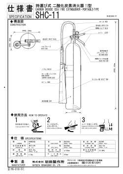
Sept. 6, 1938.
I
A. G. H. VANDERPOEL
2,129,609
AUTOMATIC FUEL MIXTURE AND SCAVENGING GAS‘ CONTROL DEVICE
Filed Oct. 26, 1936
2,129,609
Patented Sept. 6., 1938
UNITED STATES
PATENT OFFICE.
2,129,609
AUTOMATIC FUEL MIXTURE AND- SCAV
ENGING GAS CONTROL DEVICE
Albert G. H. Vanderpoel, Wilmar, Calif., assignor
of one-third to James O’Laverty and one-third
to David E. Seward, both of Los Angeles, Calif.
Application October 26, 1936, Serial No. 107,643
20 Claims. (Cl. 123-119)
This invention has to do with fuel saving de
vices or "deceleration control devices" of the
‘general character shown and described in United
States Letters Patent No. 2,017,878, issued to me
5 on October 22, 1935, and my copending applica
tions, Ser. No. 20,997, ?led May 11, 1935, and Ser.
No. 95,126, ?led August 10, 1936. The present in
vention is more particularly directed to improve
ments in the type of device shown in my co
1O
pending application last referred to above, such
improvements being designed to increase the uni
versal adaptability of the device as an attach
ment for all conventional types of carbureters.
The general object of the present invention, as
intake manifold just mentioned above. Also in
both devices vent means, controlled by throttle
position, are provided to relieve or break the suc
tion applied to the suction actuated member
thereby permitting the return of the flow con
trol means to their normal operating position.
In the device of my copending application the
communication of suction from the intake mani
fold or suction passage was controlled by a pilot
piston associated with a suction control valve
and the venting of the suction actuated member
was accomplished through the use of a sleeve
valve normally held in an open position by a
yieldable member such as a compression spring.
As has been previously indicated my present
15 was the case in my copending application'last re
ferred to above, is to provide means, auxiliary to - invention is primarily designed for use as an at
the carbureter, for controlling the ?ow of gas
to the intake manifold. The chief purpose of
such auxiliary means is to automatically cut off
the carbureter proper from the intake manifold
when the throttle valve is retarded to idling posi
tion with the engine running on momentum at a
speed greater than idling speed thereby prevent
ing the admission of raw fuel to the intake
manifold and the disadvantages attending such
admission under these operating conditions. This
control of ?ow of gas to the intake manifold is
further e?'ected by the admission of a scaveng
ing gas during such time as the carbureter is
30 cut off in the manner pointed above.
The present invention like that ‘of my copend
ing application, Ser. No. 95,126, makes use of two
factors, attending the operation of the engine
and the carbureter throttle valve, for obtaining
23 Ch this control of gas ?ow to, ‘the intake manifold,
such two factors being the manifold depression
and the throttle position.
The device is so de
, signed that the initial action (that is the clo
sure or shutting", off of the suction passage to
40 the intake manifold and the opening of the
scavenging gas inlet) makes use of both these
factors, and the secondary action (that is the
opening of the suction passage and the closure
of the scavenging gas inlet) may be effected by
45 either of these factors independently of each
other depending upon which control factor comes
into action ?rst.
i
In both the device of my present application
_ and that of my application last referred to above,
an abnormally high depression in the intake
manifold, which attends "closure" of the throttle
valve with the engine running at above idling
speed, is utilized to operate a suction actuated
member which is operatively associated with the
55 means for controlling the ?ow of gas to the
5
tachment, and in such capacity, it will be seen‘
that the position which the attachment unit
occupies when' in use, will depend entirely upon
the design of the intake manifold and carbureter Ni 0
connection in the particular engine on which it
is used.
In this regard I have found that the
pilot piston arrangement of my copending ap
plication .last discussed above is quite sensitive
to changes in position and in order that the
adaptability of the device in different types of
connections may be enhanced, it becomes the
chief object of the presentlinvention to provide
an improved pilot member for actuating the
suction' control valve which will operate with
equal sensitiveness irrespective of the position
of the unit.
.
'
The sleeve valve venting arrangement of my
copending application requires the use of a spe
cial throttle valve actuating lever to effect its
operation, and since the position of the throttle
valve, shaft varies with different types of carbu
reters, this former device required a special
throttle lever for each di?erent carbureter de
sign. It therefore becomes a further object of
this invention to provide an improved vent valve
and vent valve actuating means which does not
re?uire the replacement of any standard parts
on the carbureter, but employs a simple and in- ‘
expensive cam member or cam plate which may
be adjustably attached to a standard throttle
lever. Thus it will be seen that by providing cam
plates for the different throttle lever designs,
the unit can be sold as a complete attachment
‘and does not reqiure the replacement of any 50
standard parts.
.
The details in the construction of a preferred
embodiment of my invention together with other
objects attending its production, will be best
appreciated from the following description of the
2,129,609
accompanying drawing, which is chosen for illus
trative purpose only and in which:
Fig. 1 is a sectional elevation showing a
ferred form of my invention in conjunction
the carbureter and manifold connections,
section having been taken in front of the
buretor, in a plane represented by the line
26’. The block portion 22 has a passage Pl.
therethrough, which communicates between the
pre
with
such
car
l-l
of Fig. 2;
.
Fig. 2 is a plan section taken in a plane repre
Formed or mounted on the side of the block
portion 22 is what I may term a suction cylinder
30 having a bore 3| therein adapted to receive
a piston 32. Also formed or mounted on the
block portion 22 in substantially concentric rela
sented by the line 2--2 of Fig. 1, a portion of
tion with the bore 3| is a scavenging gas inlet
said section through the diaphragm chamber be
cylinder 33 which has a bore 34 therein, adapted
_ ing off-set along the line 2—2 of Fig. 3;
Fig. 3.is a sectional elevation taken in a plane
represented by the line 3-3 of Fig. 2;
15
suction passage P of the carbureter and the in
take manifold.
Fig. 4 is a fragmentary sectional elevation
taken along the line 4-4 of Fig. 2;
Fig. 5 is a fragmentary section taken along
‘ the line 5—5 of Fig. 2; -
-
to receive a sleeve valve or piston vvalve 35.
The
piston valve 35 is shown as being connected to
the piston 32 in the suction chamber through a
rigid connecting rod 31. The scavening gas inlet 15
cylinder 33 is shown as being externally threaded
at 38 to receive a connection froml any [suitable
source of scavenging gas such as the exhaust
Fig. 6 is a fragmentary sectional elevation
20 taken along the line 5-6 of Fig. 1 with the throt
tle lever advanced to the dotted line position
shown in Fig. 1; and
Fig. 7 is an enlarged fragmentary section il
lustrating details in the construction of the vent
manifold, and is also shown as being provided
with a ?ltering medium indicated by reference
numeral 39. ‘The, piston or sleeve valve 35 is
shown as- being provided with end ports 40.
For the purposeof admitting a scavenging gas
25 valve shown in Fig. 1.
carbureter and numeral l2 indicates the inlet
connection'of an intake manifold to which the
carbureter is ordinarily attached. The car
bureter, as mentioned above, is here shown as
being of the down-draft type, but may be either
into the intake manifold, I provide a scavenging 25
gas duct 42 in the block portion 22, such duct
having an outlet port 43 in the wall of the pas
sage P1 and having an inlet port 44 located in
an annular groove 45 formed in the wall of the
bore 34 and adapted to be normally covered or 30
closed by the sleeve valve or piston member 35.
The scavenging gas duct 42 therefore, with the
attending valve and inlet connection just de
up-draft or down-draft, and is shown as having
scribed serves as one medium for controlling
a suction passage P adapted to communicate with
the flow of gas to the intake manifold.
In addition to this, the ?ow of gas to the in
take manifold is controlled by an auxiliary shut
off valve 50, which is mounted in the passage P1
on a shaft 5|, said shaft having one end 52 pro
_
More particularly describing the invention as
herein illustrated, reference numeral ll indicates
the bottom portion of a conventional down draft
the intake manifold and ‘equipped with‘ a con
ventional butter?y throttle valve l3. The throt
tle valve I3 is mounted upon a shaft l4 which
has a throttle actuating lever l5 secured to its
40 extending end.
The lever | 5 may be of any
conventional form and is adapted to be actuated
by a throttle actuating rod l6. It is the usual
practice to associate the throttle valve with some
means for adjusting its idle position and for the
45 purpose of illustration herein, I have shown such
means as comprising an adjusting screw l1
adapted to engage a projection I3 on the throt-'
tle lever.
The suction passage P of the carburetor is also
50 shown as being equipped with a Venturi throat
IS, a main fuel jet diagrammatically illustrated
at 20, and an idling by-pass shown in dotted
lines at 2“) with its outlet port 220 positioned
between the throttle valve I3, in its closed posi
55 tion, and the intake manifold.
Reference numeral 2| indicates the attach
ment contemplated by this invention which is
designed to cooperate with the carburetor II, for
controlling the flow of gas to the intake mani
60 fold connection l2 at certain stages in the oper
ation of: the engine. The attachment 2| is
housed in what I may term a block member.
This block member, to which the numeral 2|
more specifically applies, is shown as being com
prised of several interconnected parts or sections
and is chambered and bored to receive the various
cooperating parts that go to make up the at
tachment.
'
The block member 2| in this form of my in
70 vention includes a ?at block portion 22, which
is shaped to conform with the connecting ?anges
23 and 24 on the carbureter and intake manifold
respectively, and has bolt holes 25 and 25' there
through, whereby it is bolted between the ?anges
75 23 and 24 through the medium of bolts 26 and.
to the passage P1, from which it can be drawn
jecting into a chamber 53, formed between the 40
two cylinders 30 and 33 on the member 2|. The
end 52 of the shaft is provided with a crank 55,
such crank having a, pin 56 located in a slot 51
in the connecting rod 31. The chamber 53 is
shown as being provided with a cover plate 58.
45
The relative positions of the valve 50, the crank
55 and the sleeve valve member 35, with respect
to the piston 32, are such that when the piston
32 is in its fully advanced position (as shown in
Fig. 2) the auxiliary or shut-o? valve 50 is open,
and the scavenging gas control valve 35 is closed,
that is the sleeve valve 35 covers the annular
groove 45. The piston 32 is normally held in this
advance position by a compression spring 60, a
stop 5| being provided on the connecting rod 31
to limit its advancing movement.
The scavenging gas duct 42 is provided with an
adjustable valve to control the volume of gas ad
mitted therethrough, such valve being shown as
comprising a tapered stem 63 having a valve
port 84 therethrough, adapted to cooperate with
the duct 42. The stem 63 is held in place by a pin
65, a washer 61 and a compression spring 63, and
has a polygonal head 69 whereby it may be ad
Justed to vary the valve opening.
The parts described above,‘comprising the two
valves 50 and 35 and the piston member 32 for
actuating such valves, constitute, broadly, means
for controlling the ?ow of gas to the intake mani
fold, and the structure so far described 'is similar
to that described and illustrated in my copending
application, Ser. No. 95,126, hereinabove referred
to, and forms no part of the present invention ex
cept insofar as the parts thereof cooperate to form
50
55
65
70
75
2,129,609
combinations with the improved features about
to be described.
For the purpose of communicating suction from
the passage P1 to the bore 3| of the suction cyl
inder to retract the piston 22 against the action
of the spring 60, I provide what may be termed a
suction duct comprised of duct sections ‘I0, ‘Illa,
10b and ma. The duct section "is formed in the
block portion 22 and communicates with the duct
10 section ‘Illa which is formed in a second block seg
ment ‘ll mounted on the end of cylinder 30
through the medium of ?anges ‘I Ia-JI lb and bolts
‘l2-‘|2'. Duct sections 'lllb are formed radially in
a valve supporting plug ‘I3 which is mounted in
the block ‘II coaxially with' the bore ii. The
radially extending ducts 10b conununicate with
an annular groove 14, formed on the plug ‘I3,
such groove‘being positioned in alignment with
the duct section 10a. The duct section 100 com
20 prises a bore or port through the end of plug 13,
such port communicating with an enlarged bore
within the plug and having a valve seat formed at
3
position, or it may even be preferable to use a
solid cover member for the diaphragm without
‘the adjusting screw, in which case the spring 8!
would be calibrated to suit the particular type of
installation. The chamber in front of the dia 6
phragm formed by recess 83 is provided with a
vent opening 90, and an auxiliary diaphragm Si
is provided to prevent the possibility of leakage
around the valve member 15 to the chamber sur
10
rounding its reduced inner end 16.
From the foregoing description it will be seen
that when the throttle valve 13 is released and
permitted to return to idling position with the
engine running at a speed greater than normal
idling speed, the engine will continue to run ei 15
ther on its own momentum or the momentum of
the vehicle if the driving wheels are in gear, which
will result in the establishment of an abnormally
high depression in the intake manifold and the
passage P1. This high depression is communicat 20
ed to the diaphragm suction chamber 84 where it
is effective to retract the diaphragm against the
action of the spring BI and open the duct control
valve
member 15, thereby establishing suction in
The communication of suction to the bore SI of
suction cylinder 30 from the passage P1, through the suction cylinder3l which retracts the piston 32
the action of the compression spring 60.
the suction duct (1'0--1Ba—1llb-1llc) is controlled against
by a valve member ‘I5, slidably mounted in the The retraction of the piston closes the auxiliary
enlarged bore of the plug 13 and having a reduced . or shut-off valve 50 and opens the scavenging
‘inner end 16 tapered to seat on the edge of port intake valve 35 in the manner previously de
scribed. Thus the ?ow of gas to the intake mani
We.
fold is controlled by substantially completely cut
The suction control valve member 15 is nor
ting
the carbureter from the intake manifold
mally held in this closed position and is adapted and off
admitting scavenging gas thereto. When
to be opened when the suction in the passage P1
such a condition is maintained in certain types of
is “abnormally high”, that is, when the depres
carbureters, it is di?lcult to keep the chambers of
35 sion in the passage P1 is in excess of the normal the carbureter ?lled with vaporized fuel and the
idling depression for the engine. In this form of
may stall when the throttle is again open.
my invention, the opening movement of the valve motor
In order to safeguard against this, the auxiliary
15 is obtained through the medium of a diaphragm valve 50 is provided with a small bleeding ori?ce
which is mounted on the outer threaded end 18 of 50' which will communicate a small depression to
the valve member ‘I5 and is indicated by reference
numeral 19. This diaphragma ‘I9 is interposed the suction passage P so as to keep the chambers
thecarbureter filled with vaporized fuel when
‘between the outer face 80 of the block segment 1| of
the
auxiliaryvalve 50 is closed.
and a diaphragm cover section 82. The segment
If the engine is decelerating, after the throttle
its end within the enlarged passage. '
'Il and‘the cover member 82 are oppositely re
45 cessed as indicated at 83 and 84 to provide a dia- .
phragm chamber, and that portion ofthe cham
ber con?ned within the recess 84 behind the dia
phragm ‘I9 constitutes what will hereinafter be
referred to as the diaphragm suction chamber.
For the purpose of communicating suction from
50
the passage P1 to the diaphragm suction chamber
25
30
35
40
valve has been retarded to its “closed” or idling
position, the depression in the intake manifold
and the passage P1 will decrease until it has re-
turned to normal idling depression, at which time
the compression of the spring BI is su?icient to
overcome the suction in the chamber 84 and 50
therefore closes the suction control valve mem
ber 15. When this takes place the spring 60
forces the piston 32 to its fully advanced posi
duct sections ‘Illa’, 85 and 86, which are intercom. . tlon, a small bleeding orifice 92 being provided
nected with each other and which communicate in the suction cylinder wall to permit a rapid ad
55
55 with the suction duct 10, so that the depression or vance of the piston 32, thereby quickly opening‘
' ~ suction in the passage P1 is always communicated
the auxiliary valve 50 and closing the scavenging
to the diaphragm suction chamber 84.
gas valve 35.
. '
In order that a valve opening movement will be
In the event it is desired to accelerate the en
imparted to the diaphragm 19 only when the gine by opening the throttle while the depres 60
60 suction in the chamber 84 exceeds the suction ob "sion in the passage P; is still “abnormally high,"
taining at normal idling speed in‘ the engine, I means must be provided for breaking the suction,
provide a compression spring ‘I shown as being ‘ which under those conditions has been estab
interposed between the diaphragmand an ad
lished and is existing in the suction cylinder 30
justing screw 81 which bears against a cup 88 through the action described above. Also for 65
mounted on the outer end of the spring 8|. This automatic operation it is important that the
adjusting screw 81 is set and locked through the means for breaking the suction be controlled by
medium of a lock nut 89 to hold the desired com
the throttle valve actuating member l5. In the
pression in the spring 8| so that it will permit improved form ofthe invention shown in the
- 84, I provide auxiliary suction duct, comprised of
valve opening movement of the diaphragm only
70 when a predetermined suction (normal idling
depression) is applied thereto from the passage
Pi. Once this setting has been made or once the
compression valve for the spring has been deter
mined for a given carbureter installation, it may
be desirable to positively lock the screw 81 in
present application this is accomplished by pro 70
viding a vent duct 93 in the wall'of suction cyl
inder 30, such duct having an outlet port 94 com
municating with the bore 3| and having an inlet
\port 95 which is preferably situated in a plane
containing the axes of the passage P1 in the block 75
4
2,129,609
and the suction passage P of the carbureter. In
description, and it is to be understood that while
other words, the position of the inlet port 95
I have herein described and illustratedv one pre
for the vent duct is preferably situated in‘ a ver
ferred form of the invention, the invention is not
limited to the precise details‘ of construction
shown and described, but includes within its scope
whatever changes fairly come within the spirit of
the appended claims.
tical plane which will contain the axis of the
throttle valve shaft I4 when the attachment is
mounted on a carbureter. The port 95 opens into
an enlarged threaded bore 96, which contains a
,valve cap 91, such cap being locked in position by
I claim:
a jamb nut 91' and having a vent opening 98
within which a ball valve 99 is seated. The valve
99 and its associated seat are so shaped that a
1. In combination with the intake manifold, the
portion of the valve member protrudes through
the opening 98, (see Fig. 1). The valve is held
in its closed position with a portion thereof thus
protruding by means of a compression spring I00,
the strength of which is such as to always hold
valve 99 seated against the action of such suc
tion as may ever be applied within the suction
cylinder bore 3|.
,
,
carburetor and throttle valve of an internal com
ll)
bustion engine; an open block between the car
buretor throttle valve and the intake manifold; an
auxiliary valve in the opening through said block;
means biasing said auxiliary valve to open posi
tion; a housing having a suction chamber
mounted on said block; means in said suction
chamber actuated by suction applied therein for
closing said auxiliary valve; and means. for se
lectively communicating suction from the suction
passage in said carburetor and manifold to said 20
For the purpose of depressing the valve 99 to
break the suction in the bore 3| when the throt ’ suction chamber comprising a suction duct in said
tle actuating lever I5 is moved in an opening di
block having its outlet in:the suction passage
rection, I employ what may be termed a cam plate
or cam member I02, which is shown as com
prising a disc secured to the end of the throttle
shaft through a pivot screw I03, such disc being
provided within a plurality ofyarcuate slots I04
‘ whereby it may be adjustably locked against piv
otal movement on various types of throttle levers
through the medium of a screw indicated at I04’;
The edge of the cam plate I02 is provided with a
therethrough, a diaphragm housing mounted on
said suction chamber housing, a duct in said dia
phragm housing communicating with said ?rst 25
mentioned duct and having an outlet port in said
suction chamber, a valve member in said dia
phragm housing adapted to seat in said outlet
port, a diaphragm mounted in said diaphragm
housing and attached to said valve member, a duct
flange I05 which is notched at I05’. The plate is
communicating between said ?rst mentioned duct
and the region of said diaphragm housing behind
mounted so that the notch I 05' normally lies over
said diaphragm whereby said diaphragm is.
the valve 99 when the throttle valve is in idling
adapted to be moved in “a control valve opening di
position. - In other words the plate is adjusted
through the medium of one of the slot connections
I04 so that one edge I06 of the ?ange I05 is just
adjacent the valve 99 when the throttle lever is
rection, yieldable means biasing said diaphragm
to a valve closing position, said yieldable means
being set to permit valve opening movement of
said diaphragm when a predetermined suction is
retracted to idling position. In this way it will be
applied thereto.
40 seen that the ?ange I05 constitutes an arcuate
cam which has its nose (I06) adjacent the valve
99. The slot connection I 04-I 04' makes it ex
tremely easy to adjust this cam for di?erent ad
justments of the throttle valve adjusting screw
II. It will be apparent that the shape and the
radius of the cam plate I02 (aside from the cir
cular cam edge I05 and the relation of such edge
to the axis of the throttle valve) may vary for
different types of carbureters. For example, in
stead of being circular the “cam” plate may be
50
formed as a segment which may be either ?at,
?anged, or offset, depending upon the position
.which the end oi’ the throttle valve shaft occupies
with respect to the location of the valve 99 on
the attachment.
55
Assuming that sucti‘on‘has been applied in the
suction cylinder bore 9I in the manner previously
described so as to close auxiliary valve 50 and
open the scavenging valve 95, and assuming fur
ther that the throttle valve is open before the de
pression in the passage P1 has dropped to normal
idling depression, it will be seen that as soon as
the throttle valve lever I5 receives any movement
in the direction of the arrow A of Fig. l, the cir
cular cam edge I05 will engage and depress the
65
vent control valve (as illustrated in Fig. 6) , there
by breaking the suction in the suction cylinder
and permitting the return of valves 50 and 35 to
their normal positions, shown in full lines in Fig.
70 2: Furthermore, in view of the arcuate edge or
?ange' I05, the valve 99 will be held in this de
pressed position for any open position vof the
throttle beyond its normal idling position.
'
'
2. In combination with the intake manifold, the 40
carburetor and throttle valve of an internal com
bustion engine; an open block between the car
buretor throttle valve and the intake manifold;
an auxiliary valve in the opening through said
block; means biasing said auxiliary valve to open 45
position; a housing having a suction chamber
mounted on said block; means in said suction
chamber actuated by suction applied therein for I
closing said auixiliary valve; means for selectively
communicating suction from ' the suction pas
sage in said carburetor and manifoldto said suc
50
tion chamber comprising a suction duct between
said passage and said chamber, a control valve in
said duct, a diaphragm housing mounted ‘on said
suction chamber housing, a diaphragm in said 55
diaphragm housing attached to said control valve,
means communicating suction from said passage
to said diaphragm housing for imparting control
valve opening movement to said-diaphragm; and
yieldable means biasing said diaphragm to a con 00
trol valve closing position, said yieldable means
being set to permit valve opening movement of
said diaphragm when the throttle valve is closed
to idling position and the attending depression
communicated to the diaphragm from the suction 65
passage is in excess of normal idling depression,
and positive means for breaking the suction in
said suction chamber comprising a vent duct in
said suction chamber housing, a valve in the inlet
to said vent duct, a throttle valve actuating meme 70
ber,and means on said throttle valve. actuating
member for positively engaging and opening said
vent valve independently of said control valve
It is believed that the operation of the inven
when the throttle valve is opened, said last men
- tion will be clearly understood from the foregoing _ tioned means being operative to hold said vvent
5
2,129,609
valve open for all open positions of said throttle
valve.
3. In combination with the intake manifold,
the carburetor and throttle valve of an internal
combustion engine; an open block between the
carburetor throttle valve and the intake manifold;
an auxiliary valve in the opening through said
block; means biasing said auxiliary valve to open
position; a housing having a suction chamber
mounted on said block; means in said suction
chamber actuated by suction applied therein for
closing said auxiliary valve; means for selectively
communicating suction from the suction passage
in said carburetor and manifold to said suction
15 chamber comprising a suction duct between said
passage and said chamber, a control valve in said
duct, a diaphragm housing mounted on said suc
tion chamber housing, a diaphragm in said dia
phragm housing attached to said control valve,
means communicating suction from said passage
to said diaphragm housing for imparting con
trol valve opening movement to said diaphragm;
and yieldable means biasing said diaphragm to a
control valve closing position, said yieldable means
25 being set to permit valve opening movement of
said diaphragm when the throttle valve is closed
to idling position and the attending depression
communicated to the diaphragm from the suc
tion passage is in excess of normal idling de
30 pression, and positive means for breaking the
suction in said suction chamber comprising a
vent duct in said suction chamber housing, a
valve in the inlet to said vent duct, a throttle valve
actuating member, and means on said throttle
35 valve actuating member for opening said vent
valve when the throttle valve is opened, said last
mentioned means comprising a cam shaped so as
to hold the vent valve open for any position of the
throttle valve beyond idling position.
4. In combination with the intake manifold, the
carburetor and throttle valve of an‘ internal com
bustion engine; an open block between the car
buretor throttle valve and the intake manifold; an
auxiliary valve in the opening through said block;
45 means biasing said auxiliary valve to open posi
tion;
a housing having
a
suction
and shaped so as to hold the vent valve open for
any position of the throttle valve beyond idling
position.
.
5. In combination with the carburetor and in
take manifold of an internal combustion engine;
a block interposed between the carburetor and
the intake manifold, said block having a passage
communicating between the carburetor suction
passage and the manifold; a suction cylinder on
said block; a piston in said suction cylinder;
means controlled by a predetermined depression
in said block passage for communicating suction
from said block passage to said suction cylinder;
a vent duct communicating with said suction cyl- ,
inder; a valve in said vent duct; yieldable means 15
holding said vent duct valve closed; a throttle
valve‘ actuating member on said carburetor;
means on said throttle valve actuating member
for positively opening said vent valve immediately
as the throttle valve is opened beyond idling posi 20
tion, said last mentioned means being operative
to hold the vent open for all positions of the throt
tle valve beyond idling position; and means actu
ated by said piston for controlling flow of gas to
the intake manifold. _
2,5
6. In combination with the carburetor and in
take manifold of an internal combustion engine;
a block interposed between the carburetor and the
intake manifold, said block having a passage com
municating between the carburetor suction pas 30
sage and the manifold; a suction cylinder on said
block; a piston in said suction cylinder; means
controlled by a predetermined depression in said
block passage for communicating suction from
said block passage to said suction cylinder; a vent
duct communicating with said suction cylinder; a
valve in said vent duct; yieldable means holding
said vent duct valve closed; a throttle valve ac
tuating member on said carburetor; means com
prising a cam attached to said throttle valve ac
40.
tuating member, adapted to engage and hold said
vent valve in open position whenever the throttle
valve actuating member is moved to open the
throttle valve beyond idling position; and means
actuated by said piston for controlling flow of gas
chamber _ to the intake manifold.
‘7. In combination with the carburetor and in
chamber actuated by suction applied therein for take manifold of an internal combustion engine:
closing said auxiliary valve; means for selectively avblock interposed between‘the carburetor and
intake manifold, said block having a passage
communicating suction from the suction passage the
communicating between the carburetor suction
in said carburetor and manifold to said suction passage and the manifold; a suction cylinder on
chamber comprising a suction duct between said Y said block; a piston in said suction cylinder; valve
passage and said chamber, a control valve-in said means actuated by said piston for controlling ?ow
duct, a diaphragm housing mounted on said suc
of gas to said intake manifold; yieldable means
55 tion chamber housing, a diaphragm in said dia
said piston to an advanced position; and
phragm housing attached to said control valve, biasing
means communicating suction from said passage means for applying suction in said cylinder to
retract said piston comprising a suction duct hav
to said diaphragm housing for imparting con
trol valve opening movement to said diaphragm; ing an outlet in said block passage and an inlet in
and yieldable means biasing said diaphragm to a the end of said suction cylinder, a valve member
control valve closing position, said yieldable in said duct inlet movable in a direction parallel
to the axis of said cylinder, a diaphragm attached
means being set to permit valve opening move
ment of said diaphragm when the throttle valve to said valve member, a suction chamber behind
said diaphragm, an auxiliary duct for communi
is closed to idling position and the attending de
pression communicated to the diaphragm from cating suction from said block passage to said dia
the suction passage is in excess of normal idling phragm suction chamber, and ‘yieldable means
depression, and positive means for breaking the biasing said diaphragm to a duct valve closing
suction in said suction chamber comprising a position, said yieldable means being set to permit
vent duct in said suction chamber housing, a valve opening movement of said diaphragm when
valve
in the inlet to said vent duct, a throttle valve the suction communicated to said diaphragm suc
70
actuating member, and means on said throttle tion chamber exceeds a predetermined limit.
8. In combination with the carburetor and in
valve actuating member for opening said vent
valve when the throttle valve is opened, said last take manifold of an internal combustion engine: a
mentioned means comprising a cam plate adjust-l block interposed between the carburetor and the
ably mounted on said throttle actuating member intake manifold, said block having a passage com
mounted on said block; means in said suction
50
55
60
70
75
6
municating between the carburetor suction pas
tween said suction duct and said pilot suction
sage and the‘manifold; a suction cylinder on said
chamber; and yieldable means biasing said pilot
suction responsive member to normally close said
suction duct valve, said duct valve and said pilot
suction responsive member being arranged sub
stantially coaxially with said suction chamber,
block; a piston in said suction cylinder; valve
means actuated by said piston for controlling flow
of gas to said intake manifold; yieldable means
biasing said piston to an advanced position; and‘
means for applying suction in said cylinder to
retract said piston comprising a suction duct
having an outlet in said block passage and an inlet
10 in the end of said suction cylinder, a valve mem
ber in said duct inlet, a diaphragm attached to
said valve member, a suction chamber behind said
diaphragm, an auxiliary duct for communicating
suction from said block passage to said diaphragm
15 suction chamber, and yieldable means biasing said
diaphragm to a duct valve closing position, said
yieldable means being set to permit valve opening
movement of said diaphragm when the suction
communicated to said diaphragm suction cham
ber exceeds a predetermined limit; said duct valve
and said diaphragm being arranged coaxially
with said suction cylinder.
9. In combination with the carburetor and in
take manifold of an internal combustion engine:
a block interposed between the carburetor and
the intake manifold, said block having a passage
communicating between the carburetor suction
passage and the manifold; a suction cylinder on
said block; a piston in said suction cylinder; valve
means actuated by said piston for controlling flow
of gas to said intake manifold; yieldable means
biasing said piston to an advanced position; and
means for applying suction in said cylinder to re
tract said piston comprising a suction duct having
85 an outlet in said block passage and an inlet in the
end of said suction cylinder, a valve member in
said duct inlet, a diaphragm attached to said valve
member, a suction chamber behind said dia
phragm, an auxiliary duct for communicating
40 suction from said block passage to said diaphragm
suction chamber, and yieldable means biasing said
diaphragm to a duct valve closing position, said
yieldable means being set to permit valve opening
movement of said diaphragm when the suction
45 communicated to said diaphragm suction cham
ber exceeds a predetermined limit; a vent duct in
said suction cylinder; a valve in said vent duct;
yieldable means for holding said vent valve
closed; a throttle valve actuating member on 'said
50 carburetor; means comprising a cam attached to
said throttle valve actuating member adapted to
engage and hold said vent valve open whenever
the throttle valve actuating member is moved to
open the throttle beyond idling position. ,
10. For use in combination with the carburetor
and intake manifold of an internal combustion
engine, an attachment for controlling the flow of
gas to the intake manifold comprising: a block
member having a portion adapted to be inter
60 posed between the carburetor and the intake
manifold, said last mentioned portion having a
passage therethrough; a suction chamber in said
block member; a suction responsive member in
said suction chamber; valve means in said block
65 member for controlling ?ow of gas through said
block passage; means associated with said suc
tion responsive member for actuating said valve
means; a suction duct in said block member hav
ing an inlet in the end of said suction chamber
70 and an outlet in said block passage; a control
' valve in said suction duct; a pilot suction respon
sive member attached to said suction duct con
trol valve; a pilot suction chamber in said block
member behind said pilot suction responsive
76 member; an auxiliary. duct communicating be
11. For use in combination with the carburetor
and intake manifold of an internal combustion
engine, an attachment for controlling the flow
of gas to the intake manifold comprising: a 10
block member having a portion adapted to be
interposed between the carburetor and the in
take manifold, said last mentioned portion hav
ing a passage therethrough; a suction cylinder
in said block member; a piston in said suction 15
cylinder; valve means in said block member for
controlling ?ow of gas through said block pas
sage; means associated with said piston for actu
ating said valve means; a suction duct in said
block member having an inlet in the end of said 20
suction cylinder and an outlet in said block pas
sage; a control valve in said suction duct; a dia
phragm attached to said suction duct control
valve; a diaphragm suction chamber in said block
member behind said diaphragm; an auxiliary 25
duct communicating between said suction duct
and said diaphragm suction chamber; and yield
able means biasing said diaphragm to normally
close said suction duct valve, said suction duct
valve and said diaphragm being arranged in co 30
axial relation with said suction cylinder. .
12. For use in combination with the carburetor
and intake manifold of an internal combustion
engine, an attachment for controlling the flow
of gas to the intake manifold comprising: a block
member having a portion adapted to be inter
posed between the carburetor and the intake
manifold, said last mentioned portion having a
passage therethrough; a suction cylinder in said
block member; a piston in said suction cylinder; 40
valve means in said block member for controlling
?ow of gas through said block passage; means
associated with said piston for actuating said
valve means; means including a suction duct
communicating with said suction cylinder 7 for 45
applying suction therein; a vent duct in the wall
of said suction cylinder having an opening com
municating with said suction cylinder and a vent‘
opening through the wall of said cylinder; a
valve in said vent opening; a seat in said vent 50
opening adapted to be engaged by said vent
valve; and yieldable means normally holding
said vent duct valve closed agains its seat.
13. For use in combination with the carburetor
and intake manifold of aninternal combustion
engine, an attachment for controlling the flow
of gas ‘to the intake manifold comprising: a block
member having a portion adapted to be inter
posed between the carburetor and the intake
manifold, said last mentioned portion having a 60
passage therethrough; a suction cylinder in said
block member; a piston in said suction cylinder;
valve means in said block member for controlling
?ow of gas through said block passage; means
associated with said piston for actuating said 65
valve means; means including a suction duct
communicating with said suction cylinder for
applying suction therein; a vent duct communi
cating with said suction cylinder said vent duct
being independent of and separate from said 70
suction duct; a valve in said vent duct; and
yieldable means normally holding said vent duct
valve closed, said vent duct valve having a pro
truding portion adapted for engagement by an
external member for opening said valve.
7
2,129,009
ed to align with said vent valve when the throttle
is in idling position; and means actuated by said
piston for controlling flow of gas to said intake
14. In combination with the carburetor and,
intake manifold of an internal combustion en
gine: a block interposed between the carbureter
and the intake manifold, said block having a
passage communicating between the carbureter
suction passage and the manifold; a suction
cylinder on said block; a piston in said suction
manifold.
'
17. In combination with an internal combus
tion engine carbureting system having a suction
passage, a throttle, and a throttle actuating
member: a suction chamber; a suction responsive
cylinder; valve means actuated by said piston
member in said suction chamber; means con
for controlling flow of gas to said intake mani
10 fold; yieldable means biasing said piston to an
advanced position; and means for applying suc
tion in said cylinder to retract said piston com
prising a suction duct having an outlet in said
block passage and an inlet in the end of said suc
trolled by a predetermined depression in said
suction passage for communicating suction
therefrom to said suction chamber; a vent duct
communicating with said chamber; a valve in
said vent duct; yieldable means holding said vent
duct valve closed; and means associated with
said throttle actuating member adapted to en
tion cylinder, a valve member in said duct inlet,
chambers in front of and behind said diaphragm,
gage and open said vent valve immediately as ‘
an auxiliary duct for communicating suction
from said block passage to the chamber behind
said diaphragm, yieldable means biasing said dia
20 phragm to a duct valve closing position, said
said throttle is opened from idling position, said
lastmentioned means being adapted to permit
continued throttle opening movement at the
yieldable means being set to permit valve opening ~ same time holding said vent valve in open posi
and means actuated by said suction respon
movement of said diaphragm when the suction tion;
sive member for controlling flow of gas through
communicated to said diaphragm suction cham
ber exceeds a predetermined limit, and a’. second
25 ary diaphragm interposed between said duct con
trol valve member and the wall of the chamber
in front of said diaphragm.
15. For use in combination with the carbureter
and intake manifold of an internal combustion
30 engine, an attachment for controlling the flow of
gas to the intake manifold comprising: a block
member having a portion adapted to be inter
posed between the carbureter and the intake
manifold; said last mentioned portion having a
35 passage therethrough; a suction cylinder in said
block member; ‘a piston in said suction cylinder;
valve means in said block member for control
ling flow of gas through said block passage;
means associated with said piston for actuating
40 said valve means; a suction duct in- said block
member having an inlet in the end of said suc
tion cylinder and an outlet in said block passage;
a control valve member in said suction duct; a
diaphragm attached to said suction duct control
45 valve member; a diaphragm suction chamber
in said block member behind said diaphragm; av
diaphragm relief chamber in front of said dia
phragm; auxiliary duct means communicating
between said diaphragm suction chamber and
50 said block passage; yieldable means biasing said
diaphragm to normally close said suction ‘duct
valve; and an auxiliary diaphragm interposed
between said duct control valve member and the
wall of said relief chamber.
16. In combination with the carbureter and
intake manifold of an mternal combustion en
gine: a throttle actuating member associated
with said carbureter; a block interposed between
the carbureter and the intake manifold, said
60 block having a passage communicating between
the carbureter suction passage and the mani
fold; a suction cylinder on said block; a piston
in said suction cylinder; means controlled by a
55
predetermined depression in said block passage
65 for communicating suction from said block pas
sage to said suction cylinder; a vent duct com
municating with said suction cylinder; a valve
in said vent duct; yieldable means holding said
vent duct valve closed; means comprising a
70 ?anged disc mounted on said throttle actuating
member with an edge thereof in alignment with
said vent duct valve adapted to engage and hold
said vent valve in open position whenever the
throttle actuating member is moved to open the
throttle, said disc having an edge opening adapt
said suction passage.
‘
-
,
18. In combination with an internal combus
tion engine carbureting system having a suction
passage, a throttle, and a throttle actuating
member: a suction chamber; a suctionresponsive
member in said suction chamber; means con
trolled by a predetermined depression in said
suction passage for communicating suction
therefrom to said suction chamber; a vent duct
communicating with said chamber; a valve in
said vent duct; yieldable means holding said vent
duct valve closed; and means associated with
said throttle actuating member adapted to en
gage and open said vent valve immediately as
said throttle is opened from idling position, said
last mentioned means comprising a cam member.
adapted to hold said-vent valve open with con-. 40
tinued throttle opening movement; and means
actuated by said suction responsive member for
controlling flow of gas through said suction pas
sage.
‘
19. In combination with‘an internal combus 45
tion engine carbureting system having a suction
passage, a throttle, and a throttle actuating
member: a suction chamber; a suction responsive
member in said suction chamber; means con
trolled by a predetermined depression in said suc
tion passage for communicating suction there
from to said suction chamber; a vent duct com
municating with said chamber; a valve in said
vent duct; yieldable means holding said vent duct ,
valve closed; and means associated with said 55
throttle actuating member adapted to engage
and open said vent valve immediately as said
throttle is opened from idlingposition, said last
mentioned means comprising a ?anged disc
mounted on said throttle actuating member with 60
an edge thereof in alignment with said vent duct
valve adapted to engage and hold said vent valve
in open position whenever the throttle actuating
member is moved to open the throttle, said disc
having an edge opening adapted to align with 65
said vent valve when the throttle is in idling posi
tion; and means actuated by said suction respon
sive member for controlling ?ow of gas through
said suction passage.
20. In combination with the suction passage 70
of a‘ carbureter and the intake manifold of an in
ternal combustion engine: a suction chamber;
a suction responsive member in said suction
chamber; valve means actuated by said suction
responsive member for controlling flow of gas to
8
3,129,609
said intake manifold; yieldable means biasing
said suction responsive member to an advanced
position; and means for applying suction in said
suction chamber to retract said suction respon
sive member comprising a suction duct having
an outlet in said suction passage and an inlet
in said suction chamber, a control valve member
in said duct inlet, a. diaphragm for actuating said
control valve member, chambers in front 01' and
behind said diaphragm, an auxiliary duct com
municating suction from said suction passage to
the chamber behind said diaphragm, yieldable
means biasing said diaphragm to a control valve
closing position, and a. secondary diaphragm 5
interposed between said duct control valve mem
ber and the wall of the chamber in front. of said
diaphragm.
'
ALBERT G. H. VANDERPOEL.‘
© Copyright 2026 ExpyDoc