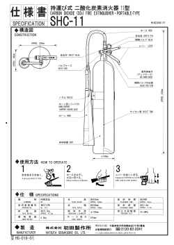
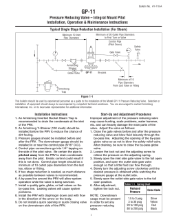
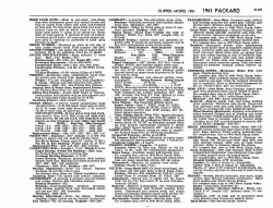
Electronic Brewer Model Numbers 1015002, 1015003, 1015004, 1015005, 1015006, 1015010, 1015020, 1015021, 1015023, 1015024, 1015025, 1015026, 1015028 20333 S. Normandie Ave., Torrance, CA 90502-1215 800-421-6860 • 310-787-5444 • Fax 310-787-5412 USA E-mail: [email protected] INT’L E-mail: [email protected] Website: brewmatic.com Instructions Number: 9600240 Rev. K 2/09 I n s ta lla tio n , P a r ts & S e r vice BREWMATIC C21 IMPORTANT INFORMATION & SAFEGUARDS Read all instructions and safeguards included in the packaging carefully and completely before installing or operating this appliance. Save all instructions for future reference. To reduce the risk of fire or electric shock, do not remove covers. There are no user serviceable parts inside. Repairs should be done by authorized service personnel only. If this appliance should fail to operate properly, contact the nearest Brewmatic Authorized Service Center or you can contact Brewmatic direct at 800-421-6860. Only Authorized Replacement Parts Should Be Used. Part substitutions could create a fire hazard and the risk of personal injury. The use of replacement parts or accessory attachments not recommended by Brewmatic may be hazardous. Do Not By-Pass Any Safety Mechanisms Or Operate This Appliance Without Covers In Place. Brewmatic requires that all safety devices and covers be in place and functioning at all times to guard against a fire hazard and the risk of personal injury. Brewmatic Does Not Recommend, And Will Not Furnish Anyone With Information For Changing The Electrical Rating Of Any Appliance Manufactured Or Distributed By Brewmatic. Brewmatic will not approve of any unauthorized changes to the basic design of this appliance. Any modification or alteration to the appliance may create a fire hazard, may create a risk of personal injury, may void the safety listings and may void the warranty. Do not touch hot surfaces. Use handles or knobs whenever possible. Do not let power cord hang over the edge of table, counter or touch hot surfaces. Close supervision is necessary when any appliance is used by or near children. Unplug from outlet and allow to cool before servicing or cleaning. Do not use outdoors. Do not use appliance for other than intended use. Due to periodic reviews and changes in listing standards, listings and approvals may change at any time. For current listing and approval information contact Brewmatic. All procedures, diagrams and specifications contained in this manual are based on the latest information available at the time of publication. Information, parts and specifications are subject to change without notice. Due to periodic reviews and changes in listing standards, listings and approvals may change at any time. For current listing and approval information contact Brewmatic. Plumbing connections - All plumbing connections to water supply lines and drains should be performed by a licensed plumber complying with all applicable plumbing codes having jurisdiction. Electrical connections - With the exception of cords with plugs already attached, all electrical connections or alterations to the power supply should be performed by a licensed electrician complying with all applicable electrical codes having jurisdiction. When calling for information, parts or service, have the following information available: Model Number: Voltage: Serial Number: Amps: Phase: Date Of Purchase: Electrical information may be obtained from the electrical information nameplate located on the appliance. SAVE THESE INFORMATION LIMITED WARRANTY Brewmatic warrants this product to be free of defects in material and workmanship for a period of one (1) year from the original date of purchase. Within this warranty period, Brewmatic will repair or replace, at its option, any part providing it's defective in material or workmanship. Labor is included within this warranty only during the first ninety (90) days of the warranty period. This warranty excludes defects caused by negligence, misuse, alteration, accident, prior service by unauthorized persons, and failure to follow the installation and operating instructions, including without limitation use of improper voltage or wiring and improper cleaning. This warranty applies only to new products and extends only to the original purchaser. This warranty is valid only in the United States of America and its possessions. The product warranted hereby is sold only for commercial use and is not intended for personal, family, or household purposes. To obtain warranty service, you must notify and deliver the product at your expense, with proof of purchase, to your local Brewmatic representative or to the Brewmatic Customer Service Division, within the warranty period. The repaired product will be returned to you at Brewmatic's expense. No Brewmatic representative or other person is authorized to add to or alter the foregoing in any respect. THE FOREGOING WARRANTY IS IN LIEU OF ALL OTHER WARRANTIES EXPRESSED OR IMPLIED, INCLUDING ANY IMPLIED WARRANTIES FOR MERCHANTABILITY AND FITNESS FOR A PARTICULAR PURPOSE. THIS WARRANTY EXCLUDES CONSEQUENTIAL DAMAGES. Some states do not allow limitation or exclusion of implied warranties or consequential damages. In such cases the limitations stated above may not apply to you, and your rights will be determined by applicable law. 2 APPLIANCE INFORMATION Brewmatic C21 Electronic Brewer 1015002, 1015004 1015003, 1015005 1015006 1015020, 1015023 1015021, 1015024 1015025 C21 Electronic Brewer C21 Electronic Brewer C21 Electronic Brewer C21 Electronic C21 Electronic Airpot Brewer Airpot Brewer 35 lbs 35 lbs 35 lbs 35 lbs Volts: 120 120/240 230 Watts: 1800 4105 Amps: 15 17 Model Number(s): Description: Shipping Weight: 1015026 1015010, 1015028 C21 Electronic C21 Electronic Airpot Brewer Airpot Tall Brewer C21 Electronic Brewer 35 lbs 35 lbs 35 lbs 35 lbs 120 120/240 230 120 120 - 120/240 3680 1780 3835 3520 1780 ------ 16 15 16 15.3 15 12.5 14 Awg. 12 Awg. 14 Awg., 14 Awg. 12 Awg. 12 Awg. 14 Awg. 12 Awg. 2W + Ground 3W + Ground 2W + Ground 2W + Ground 3W + Ground 2W + Ground 2W + Ground 2W + Ground Plug: NEMA 5-15P Plug Not Attached Plug Not Attached NEMA 5-15P Plug Not Attached Plug Not Attached NEMA 5-15P NEMA 5-15P Spray Head: S/S 5 Holes S/S 5 Holes S/S 5 Holes S/S 5 Holes S/S 5 Holes S/S 5 Holes S/S 5 Holes S/S 5 Holes 1/4" Flare - 90° Elbow 1/4" Flare - 90° Elbow 1/4" Flare - 90° Elbow 1/4" Flare - 90° Elbow 1/4" Flare - 90° Elbow 1/4" Flare - 90° Elbow 1/4" Flare - 90° Elbow 1/4" Flare - 90° Elbow 1.85 Gal. (237 oz.) 1.85 Gal. (237 oz.) 1.85 Gal. (237 oz.) 1.85 Gal. (237 oz.) 1.85 Gal. (237 oz.) 1.85 Gal. (237 oz.) 1.85 Gal. (237 oz.) 1.85 Gal. (237 oz.) 2 Selections 2 Selections 3 Selections 2 Selections 2 Selections 3 Selections 2 Selections 3 Selections UL Safety, UL Sanitation, CUL UL Safety, UL Sanitation, CUL CE UL Safety, UL Sanitation, CUL UL Safety, UL Sanitation, CUL CE UL Safety, UL Sanitation, CUL UL Safety, UL Sanitation, CUL Power Supply: Water Connection: HEATING INFO: Tank Capacity: Brewing Feature: Listing: 3 INSTALLATION INSTRUCTIONS WARNING CAUTION: Read these instructions completely before operating this machine. CAUTION: Incorrect installation or operating procedures will void the warranty and may damage this equipment. CAUTION: Make sure the installation instructions have been followed before attempting to operate this machine. NOTE: Check applicable building codes for information about some restrictions that may apply during this installation. SET UP: 1. Place the equipment on a sturdy, level heat resistant, non-flammable surface near power and water supply. Ensure machine is level. DO NOT CONNECT THE WATER LINE OR POWER CORD AT THIS TIME. PLUMBER’S INSTRUCTIONS: Fig. 1 (Plumbing Connection Diagram) 2. Form 3 coils of 1/4" OD copper tubing or high pressure flexible hose (not supplied) and connect to the cold water line. The coils allow the machine to be moved easily for cleaning and servicing. Flush the incoming water in the line. (See Diagram, Fig. 1) IT IS RECOMMENDED THAT AN OPTIONAL SHUT OFF VALVE AND WATER FILTER BE INSTALLED ON THE WATER LINE AT THIS TIME. 3. Attach the water line to the 1/4" flare water inlet fitting located on the rear of the machine. Hold the machine water inlet fitting with a wrench when tightening the water line. NOTE: This machine is designed to operate with a water pressure between 30 to 80 psi. When water pressure exceeds 80 psi, it is recommended that an optional water pressure regulator be installed to reduce water pressure to 50 psi. For installation of more than 25 feet from the water supply, use 3/8” OD copper tubing and use an adapter for connection as necessary. 4. Turn ON water supply. 5. Check for water leaks at the water inlet. Tighten fittings if necessary. ELECTRICAL CONNECTION: 6. Connect the power supply cord into proper power supply as indicated on the electrical nameplate. WARNING: Be certain the power supply is of the correct rating and polarity before connecting the machine’s power supply cord. Failure to follow this warning will void the warranty and may cause damage or injury. FILLING AND TESTING 7. Push the toggle switch located in the back of the machine to the On (Up position). (There will be a beep sound indicating power to the control board, the display window will show the software version for a few seconds and will shut off). 8. Press the “Power Button” in front of the machine. The display window will light up and display will show “Filling”. 9. The automatic filling will stop when the water has reached the proper level. The main tank heater will automatically turn on and the display window will indicate, “Heating Up Low” until 165°F is reached and then the display window will indicate the tank temperature while heating. 10. Allow the machine to reach the proper temperature. This will occur in approximately 20 minutes. The display window will indicate “Ready” when the proper temperature has been reached. 4 OPERATING INSTRUCTIONS 1. When the display window in front of the machine indicates “Ready”, the machine has reached the proper brewing temperature and is ready for use. 2. Place a desired amount of fresh ground coffee in the filter paper and place in the brew cone. Slide the brew cone into the cone slides. Push the brew cone all the way back. 3. Place a clean empty decanter on the bottom warmer directly under the brew cone. 4. Press the desired brew button. Note: When a brew button is pressed, the bottom warmer will automatically turn On. The warmer time settings are set to 45 minutes (factory default) to “Beep” every 3 seconds for 5 minutes or until manually turned off. (See Page 6 for programming the warmer time setting) 5. In a few seconds, fresh coffee will start to flow into the decanter. Note: When the brew cycle is finished dripping out of the brew cone, it will beep to signal the operator that the brew cycle is complete. 6. To brew another decanter of fresh coffee, repeat steps 1 thru 4. Note: It is possible to press the brew button before the display window indicates “Ready”. However, an empty decanter must be placed on the bottom warmer and the brew cone with fresh ground coffee and filter be inserted into the cone slides. The machine will automatically brew when the proper brewing temperature has been reached and the display window indicates “Ready”. PROGRAM / SETUP INFORMATION READ AND FOLLOW THE CAUTIONS BELOW BEFORE ATTEMPTING TO PROGRAM THIS MACHINE. This machine is programmed as follows: Decanter Brewer Model No. 1015002, 1015003, 1015004, 1015005 & 1015006 & 1015010: Airpot Brewer Model No. 1015020, 1015021, 1015023, 1015024 & 1015025 & 1015028: Decanter (Approx.): Button 1 Set for (137 Sec) 64 Oz.; Button 2 Set for (71 Sec) 32 Oz.; (Model 1015006 & 1015010 Only: Button 3 Set for (35 Sec) 16 Oz.) Airpot (Approx.): Button 1 Set for (232 Sec) 101 Oz.; Button 2 Set for (160 Sec) 74 Oz.; (Model 1015025 & 1015028 Only: Button 3 Set for (137 Sec) 64 Oz.) (Note: These settings are programmable to different volumes.) PROGRAMMING INSTRUCTIONS FOR POUCH PACK USE: Replace the spray head with a 1 hole spray head (#6000604) Revise brew time to 315 seconds, no pulse or pre-infusion and change drip out time to 30 seconds. PROGRAM/SETUP: Note: The following steps show how to complete all steps in the program mode. Steps may be bypassed by leaving the setting for the step to “N” (No) unless changes are required. This is described in the procedure. To enter the program with brewer in the OFF mode, press and hold “Cancel Brew” and “Power” buttons simultaneously for 5 seconds. To exit the program mode, press the power button. If at any time during the program mode a button is not pressed for 60 seconds, the program will exit automatically. 5 USA: AIRPOT MODELS ONLY USA: DECANTER MODELS ONLY INTERNATIONAL: AIRPOT MODELS ONLY INTERNATIONAL AND DUAL VOLTAGE MODELS DISPLAY WILL SHOW PROGRAM MODE Press “Cancel Button” to advance to next sequence (On display). Press button 1 or 2 (Full or Half) to increase or decrease (change values) on display setting or toggle the setting as required. Press “Full Brew” button to change display “Y” or “N”. DECANTER AND AIRPOT DISPLAY SETTINGS & - Indicates information being displayed in the display window (Press “Cancel” button to advance to the next display setting). & Tank Temp - Use buttons 1 or 2 to change. & Style ¾ Decanter Brewer ¾ Other – Types of brewers using the controller (Airpots, etc. with additional set of defaults) ¾ Warmers Y/N - Enables or disables warmers. (Not on Airpot models) & Standard Y/N – “Yes” - for typical brew time settings; “No” – for custom setting for pulse brew and pre-infusion – see custom set up procedures. & Set Brew Time N? If N, brew settings will be skipped. If Y, see “Custom Programming Setting” below) ¾ Button 1 Total Brew Valve and Timer Setting – Amount of time required out of dump valve for correct water volume. ¾ Drip Delay – Drip out time for brew cone to empty after brew valve shuts off (Added to total brew time ¾ Repeat for other brew buttons. & Chg Warm Time? N – Length of time warmers are ON in minutes before shutting off, or if programmed not to shut off, the LED will flash and the beeper will sound. (See machine settings) Note: Times can only be changed when warmers are enabled. (Factory set at 45 minutes. Not on Airpot models). & Standby – Energy saving feature displayed in hours, to decrease power after preset time. Settings from 0 to 18 hours. (Factory set at 8 hours). & Filter? N – Feature that will monitor water filter capacity (when set) and filter life. The machine will show message to change filter after total filter capacity has been reached. & Mach Settings? N • Change To Y ¾ Temp Unit “C” (Celsius) or “F” (Fahrenheit) – This will change display value 6 ¾ Self Service? Y/N – – (Y-Locks out the keypad for self service application). To unlock the keypad (for 10 seconds) to enable brewing, press and hold the “Cancel” button for 5-seconds. To cancel this feature, 1st unlock the keypad and then go into the program mode under machine settings and change to “N”. ¾ Beeper? Y/N – Turns the beeper On or Off. ¾ Warmer Off? Y/N – If Y, warmer will shut off at end of programmed time. If N warmer will not shut off but the LED light will flash continuously and the beeper will sound every 5 minutes. Not on Airpot models. ¾ Display Temp? Y/N – If N, temperature will not be displayed during brew cycle. If Y, the display will show the temperature during brew cycle and at heat up of tank. . ¾ Load Defaults? N – If changed to Y, the factory-programmed settings will be reloaded, changing the custom settings if applicable. CUSTOM SETTINGS FOR PRE-INFUSION, PULSE BREW AND BYPASS VALVE SETTINGS. (If required) In program mode, go to standard? Y/N and change to “N” & Set Brew Time Setting to “Y” Adjust as required. (For flow rate reference, see page 8) & Pre-Infuse Y/N - For pre wetting of product prior to brewing. ¾ Y = Pre-Infuse Time – Amount of hot water on product prior to brew cycle. ¾ Pre-Inf Dly Time – Amount of time delay after pre infusion and prior to brew cycle. & Pulse Brew N • Change To Y ¾ Brew Time – Will not be less than the total brew valve time setting (original brew time-dump valve) Increase the extended brew time as required. ¾ PLS = ( ) On/Off – Set for number of pulses required up to 10. Controller will automatically calculate the On and Off time per the extended brew time setting. ¾ Set Bypass TM? N – Time setting for machines equipped with an additional water valve. This feature can be set (programmed) the same as set brew time settings and pulse brewing options. ¾ Drip Delay – Drip out time for brew cone to empty after brew valve shuts off. (Added to total brew time). HIDDEN MENU FUNCTION: (To be accessed by trained personnel only.) There is a hidden menu for the factory setting. To access this menu, the control must be in the programming mode. While in the program mode, press and hold the POWER and CANCEL buttons simultaneously for 10 seconds. & - Indicates information being displayed in the display window (Press “Cancel” button to advance to the next display setting). & FACTORY SETTINGS. Custom set up for this specific machine. & VOLUME UNIT = X. Use button 1 or 2 to change ¾ ¾ G =Gallons L = Liters. & INFLOW RATE X.XXu. The rate is in gallons per minute. Use brew button 1 or 2 to change the settings. This rate is used to calculate the total volume and filter life. The inflow is how much water has been put back into the tank through the fill VALVE and matches the machine’s flow control. & TMP CAL XXXu #XX. ¾ ¾ °C = Centigrade °F = Fahrenheit Where “XXX” is the temperature and “U” is the unit in degrees °C or °F. The “#XX” is the amount of ± offset that has been added to the temperature reading. An offset of 0 is the original temperature reading as calibrated at the factory. The user can change the temperature 7 reading by using brew button 1 or 2 to change the “XXXU” reading. The amount of offset will be displayed. Only ± 10°F or 5°C offset can be programmed. TOT VOL XXXXXXU. Total volume of water used by this machine. This reading is not re-settable. ¾ ¾ G =Gallons L = Liters. The XXXXXX is the value and the “U” is the unit in G or L (gallons or liter). BRW CYCL S XXXXXX. This is the amount of completed brew cycles. This reading is not re-settable. & BUTTONS P/SIDE X. Use button 1 or 2 to change. ¾ ¾ SINGLE - Standard DUAL & FILL DELAY XS. The fill delay is the amount of time before energizing the fill solenoid after the water has fallen off the probe. Use brew button 1 or 2 to toggle between the settings. & FACTORY SETTINGS. To exit the program mode, press the POWER button. The control will return to the OFF mode. PROGRAM FLOW RATE SETTING FOR REFERENCE ONLY – SOME MACHINES MAY VARY For Decanter and Airpot Models 5 Hole Spray Head P/N: 1031320 (Approximate Flow Rate: .43 Oz/Sec. 64 Oz. 32 Oz. 16 Oz. 3 Liter (101.5 Oz.) 2.2 Liter (74.4 Oz.) = = = = = 147 Seconds 74 Seconds 37 Seconds 238 Seconds 175 Seconds 8 Hole Spray Head P/N: 1040057 (Approximate Flow Rate: .62 Oz/Sec. 128 Oz. (1 Gallon) 64 Oz. 32 Oz. 16 Oz. 3 Liter (101.5 Oz.) 2.2 Liter (74.4 Oz.) 2.5 Liter (84.5 Oz.) = = = = = = = 204 Seconds 102 Seconds 51 Seconds 26 Seconds 163 Seconds 119 Seconds 130 Seconds This completes the custom setup time/volume procedure. Exit the program by pressing the POWER button or CANCEL BREW button to advance thru the program sequence. PROGRAMMING FOR POUCH PACK USE – For Decanter Models Only. In program mode, go to standard? Y/N and change to “Y” & Set Brew Time Setting to “Y” Adjust Brew Time Setting to: 315 Seconds & Pre-Infuse Y/N : N & Pulse Brew N ¾ Drip Delay : 30 Seconds 8 TROUBLE SHOOTING GUIDE WARNING ALL SERVICE MUST BE PERFORMED BY A COMPANY APPROVED QUALIFIED SERVICE PERSONNEL. Read and follow the cautions below before attempting to service this machine. Read and verify that the installation instructions have been followed before attempting to operate this appliance. Incorrect installation or operating procedures will void the warranty and may damage this appliance. Unplug the power cord before servicing, unless electrical testing is required. Be certain the power supply is of the correct rating and polarity before connecting the power supply cord, the chassis must be grounded to prevent possible electric shock. Failure to heed this warning may damage this appliance and may cause injury. Under no circumstance should the hi-limit thermostat be by-passed. In the event of failure the hi-limit thermostat should be replaced. Use only original or authorized replacement parts. Carefully inspect the internal wiring for wear or damage when servicing. Worn or damage wiring may cause malfunction s and premature component failures. Replace any wires that have loose connections, damaged insulation or show evidence of overheating. When repairing or replacing internal electrical wiring, in part or in whole, use only terminals and wires with the same rating, gauge and insulation covering. FOR ANY ERROR CODES AND BEFORE TROUBLE SHOOTING, RESET THE MACHINE BY TURNING OFF THE SWITCH IN THE BACK OF THE MACHINE AND TURNING THE SWITCH BACK ON. Symptom 1. The coffee machine will not come ON when the power switch in front is turned ON. Solutions The power supply cord is not plugged in. No power at the wall outlet. Power switch in back of the machine is not On. Power supply board defective – Replace. 2. The coffee machine trips the building circuit breakers. Too many appliances are connected on one electrical outlet. The electrical circuit amperage rating is too low. 3. The machine has shut down and display window shows “SHORTED PROBE”. All LED’s are flashing and beeper sounds. (If enabled) The temperature probe has shorted. The probe trip point above 239°F. The machine has shut down and display window shows “OPEN PROBE”. All LED’s are flashing and beeper sounds. (If enabled) Open temperature probe below 32°F Trip Point. The machine has shut down and display window shows “HEAT ERROR”. All LED’s are flashing and beeper sounds. (If enabled) If not heating, check power voltage at the tank heater. If voltage is present, Replace heater. If machine doesn’t heat within designed time, the display window will show “HEATERROR”. If heating and boiling, Replace the power supply board. The machine has shut down and display window shows “INIT FILL ERROR”. All LED’s are flashing and beeper sounds. (If enabled) Check the water supply if turned on. The machine has shut down and display window shows “FILL ERROR”. All LED’s are flashing and beeper sounds. (If enabled) Check the voltage to the valve. If voltage is present at the valve check the valve screen if plugged up. Clean valve screen if necessary. Check to make sure the water supply is on. 4. 5. 6. Check for loose connection. Replace temperature probe Check for loose connection. Replace temperature probe If voltage is not present, Check the hi-limit. Note: Check the voltage with the heater connected. Do not disconnect the heater Reset the machine. Check to make sure water pressure is at least 20 PSI. Check voltage to inlet water valve. Tank not filled to probe within time limit. 7. Check the incoming water pressure. Make sure pressure is at least 20 PSI. Replace the valve if necessary. 8. The machine keeps brewing after the cycle is finished. The brew valve is stuck open. Replace the valve if necessary. 9. The inlet valve stays open and water keeps coming out of the brew cone. Check the probe connection for good continuity. The inlet valve is stuck open and does not close. Replace the valve if necessary. Check the valve for proper function. Replace if necessary. Bad relay on the power board. Replace the power supply board. If pressing the power button in front of the machine and nothing happens, shut the toggle switch off at the back of the machine. If still nothing happens, Replace the Valve. If the valve shuts off when toggle switch is turned off, Replace the power supply board. Water feeding the machine does not have enough conductivity. (Caused by using Reverse Osmosis Systems) 9 WIRE DIAGRAM 120 Volts 120/240 Volts 10 WIRE DIAGRAM 230 Volts 120V - 120/240 Volts POWER SUPPLY CONNECTIONS 120V & 120/240V Power Connection 11 220V Power Connection PARTS DIAGRAM & PARTS LIST – AIRPOT MODELS Item No. Part No. Description 1 1015174 1015255 Weld Assy., Shell Weld Assy., Shell, Tall 2 1015175 Weld Assy., Top 4 1015129 Weld Assy., Top Cover 6 1015135 Rail, Right 7 1015136 Rail, Left 8 1015138 1015256 Panel, Front Panel, Front, Tall 18 9903458 Cable, Clamp 19 9903590 9903630 9903431 Cord Power Supply –120V Cord Power Supply -120/240V Cord Power Supply - 230V 20 1010254 Gasket, Tank 21 1015125 Lid, Tank 22 1015144 Grommet, Probe 24 NA 31 1015239 Shield 32 9003141 Screw, Machine #6-32 x 5/8 42 9903549 Clamp, Hose, Double Tang 1/2" 43 9916300 Probe, Liquid Level 51 6000825 Faucet, Assy., Solder 55 1015186 Plate, Faucet Lock 56 9202118 Nut, Hex 1/2-20 62 9001259 Screw, Machine #8-32 x 3/8 Pan Hd. S/S 70 9906105 Foot, Rubber Washer 71 9916275 Plug, Square 75 6000872 Guide, Thermos 76 5003146 Screw, Shoulder #6-32 x .406 77 1015193 Bracket, Tank Hold Down 78 9201146 Nut, Hex #10-32 Self Locking 1015188 Brew Cone Assy. (See Page 15) NA NOT SHOWN 79 12 PARTS DIAGRAM & PARTS LIST– AIRPOT MODELS Item No. Part No. Description 5 NA See Page 14 8 * 23 9919257 Switch, Toggle, 240V 20A 25 6000937 Sensor, Replacement Assy. 30 9922285 9922303 6000834 Valve, Dump W/Air Elbow 120V & 120/240V Valve, Dump W/Air Elbow 230V Clip, Valve 35 9902346 Drain Plug, Bumper (White) 36 1034182 Tube, Silicone 6” Lg. Spray Head 37 1034162 Tube, Silicone 19” Lg. Tank Drain 38 6000858 Tube, Silicone 29” Lg. Tank Fill 39 6000736 Tube, Silicone 2” Lg. Overflow (Top) 40 6000707 Tube, Silicone 9-1/2” Lg. Faucet 29 * * Part of Item #58 41 1031268 Tube, Silicone 3-5/8” Lg. Overflow (Bottom) 42 9903549 Clamp, Hose Double Tang 1/2" 44 1040389 Terminal, Insulator 45 9918252 Ring, Retainer 52 9922290 9922289 Valve, Inlet 120V & 120/240V Valve, Inlet 230V 54 9906580 Fitting, Tee PP 3/8 x 3/8 x 1/8 57 9001253 Screw, Machine 4mm x 5mm Slt Hd. 58 1015226 Power Board Assy. 59 1015143 Bracket, Terminal Block 60 9902402 61 * 62 9001259 Screw, Machine #8-32 x 3/8 Pan Hd. 64 9303103 Washer, Lock W/Int Tooth #6 65 9001225 68 * 69 9205105 Terminal Block, 5 Pole Part of Item #58 Screw, Machine #6-32 x 3/4" Slt. Hd. Part of Item #58 Nut, Hex Lock #8-32 S/S With Nylon Insert * PARTS DIAGRAM & PARTS LIST– HOOD Item No. Part No. 10 9301181 Washer, .628 OD x .406 IS x .032 Thk. Santoprene 11 9202122 Nut, Hex 1/8-27 x .562 OD x .109 Thk. 12 9202120 Nut, Hex 1/8-27 x .562 OD x .062 Thk 13 1015264 Fitting, Spray Head 14 1031320 Spray Head 15 1031296 Tube, Overflow 16 9914360 Nut, Push-On 5/16 S/S Description 26 9919543 Spacer, .25 OD x 1/4 ID x 5/8” Lg. 27 9902407 Board, Control 28 9205104 Nut, Hex Lock #6-32 With Nylon Insert 29 1041034 1041035 Switch Assy., Membrane – Decanter Models (2 Brew Buttons) Switch Assy., Membrane – Airpot Models (2 Brew Buttons) 29A 1040918 29B 1040931 Switch Assy., Membrane – Decanter Models (3 Brew Buttons) Switch Assy., Membrane – Airpot Models (3 Brew Buttons) (Not Shown) 1040947 Label, Faucet (Required with item 29A & 29B) 13 PARTS DIAGRAM & PARTS LIST – TANK ASSEMBLY Item No. 1 Part No. Description 2 1015122 1015289 9920371 Weld Assy., Tank Weld Assy., Tank Dual Voltage (1015010 & 1015028) Thermostat, Hi-Limit 3 9301183 Washer, .75 OD x .5 ID x .061 Thk Rubber 4 2000129 Siphon Fitting, Tank 5 6000752 Fitting, Solenoid 6 9915155 “O”-Ring 1” OD x .864 ID x .070 Thk. 7 9207101 Nut, Pipe ¼ Thd. Brass 8 6000833 Nut, Hex 1/2 Str. Pipe Thd. .25 Thk. 9 9303104 Washer, Lock W/Int. Tooth #8 NPS 10 9201104 Nut, Hex Std. #8-32 NPS 11 9905380 9905381 9905378 9905397 Element, Immersion - 120V 1750W (Airpot) Element, Immersion - 120V 1500W (Decanters) Element, Immersion - 230V 3500W (1015006 & 025) Element, Immersion - 120V-120/240V 1500/3000W (1015010 & 1015028) 12 9906166 Fitting, 1/8 MPT x 1/8 Ferrule 13 1015123 Inlet Tube Assy. 14 6000818 Nut, Hex 3/8 Str. Pipe Thd. Brass 15 9915153 “O”- Ring Ethylene/Propylene 16 9301211 Washer, Seal Complete Tank Assy: Including all items above (items 1 thru 16) 1015146 1015105 1015145 1015290 Tank Assy. 120V Tank Assy. 120/240 & 230V. Tank Assy. Airpot 120V. Tank Assy. 120, 120/240V 1500/3000W PARTS DIAGRAM – DECANTER MODELS Item No. Part No. Description 1 1A 1015175 1015242 Hood C21 S/S Weld Assy., Base Shell 2 1015200 Weld Assy., Front Panel Lower S/S 4 1015103 Top Cover Assy. S/S 7 6003093 Element Pan Assy. 18 9903458 Cable, Clamp 19 9903590 9903630 9903431 Cord, Power Supply – 120V Cord, Power Supply – 120/240V Cord, Power Supply – 230V 20 1010254 Gasket, Tank 21 1015125 Lid, Tank 22 1015144 Grommet, Probe 24 1015196 Cover, Front Panel Upper S/S 25 9916176 Plug, Snap 32 1015239 Shield 42 9903549 Clamp, Hose Double Tang 1/2" 43 9916300 Probe, Liquid Level 52 6000825 Faucet, Assy. 56 9202118 Nut, Hex 1/2-20 Brass 74 9915193 Bracket, Tank Hold Down 76 1015188 Brew Cone Assy. (Complete) See pg.15 75 9201146 Nut, Hex #10-32 Self Locking 14 COMPLETE BREW CONE ASSY: Includes (Items 1, 2 & 3) Item No. Part No. Description 1 1015192 Basket, Wide Bottom 2 1015137 Cone, Wide Bottom S/S 3 9908203 Handle, Cone PARTS DIAGRAM & PARTS LIST– DECANTER MODELS Item No. 5 8 9 23 26 30 31 36 37 38 39 40 41 42 45 46 53 57 58 59 60 61 62 63 67 68 70 71 72 73 77 * * 15 Part No. Description 1015118 NA Bottom, Shell See Page 14 Board, Power Assy. C21 Board, Power Assy. C21 (For 1015006 & 025 Only) Toggle Switch Sensor, Replacement Assy. 1015226 1015266 9919257 6000937 9922285 9922303 6000834 9902346 1034182 1034162 6000898 6000736 1031268 9903549 1040389 9918252 9922290 9922289 9001253 1015143 * 9902402 9906580 9303103 9001225 9906571 9903617 9001259 * 9205105 6000707 * Valve, Dump W/Air Elbow 120V & 120/240V Valve, Dump W/Air Elbow 230V Clip, Valve Drain Plug, Bumper Tube, Silicone, 6” Lg. Spray Head Tube, Silicone, 19” Lg. Tank Drain Tube, Silicone, 23” Lg. Fill Tube, Silicone, 2” Lg. Overflow (Top) Tube, Silicone, 3-5/8” Lg. Overflow (Bottom,) Clamp, Hose, Double Clamp Terminal Insulator Ring, Retainer Valve, Inlet 120V & 120/240V Valve, Inlet 230V Screw, Machine 4mm x 5mm Slt. Hd. Bracket, Terminal Part of Item #9 Terminal Block, 5 Pole Fitting, Tee, PP, 3/8 x 3/8 x 1/8 Washer, Lock W/Int Tooth #6 Screw, Machine #6-32 x .75” Lg Foot, Appliance Black Plastic Cap, Black Vinyl Screw, Machine, Pan Hd. #8-32 x 3/8 S/S Part of Item #9 Nut, Hex, Lock #8-32 S/S W/Nylon Insert Tube, Silicone, 9-1/2” Lg. Faucet Part of Item #9 NOTES: 16 Mailing Address: PO Box 2959 Torrance, CA 90509-2959 Shipping Address: 3828 S. Main St. Los Angeles, CA 90037 310-787-5444 • 800-421-6860 • Fax 310-787-5412 USA E-mail: [email protected] Int’l E-mail: [email protected] Website: brewmatic.com
© Copyright 2024 ExpyDoc