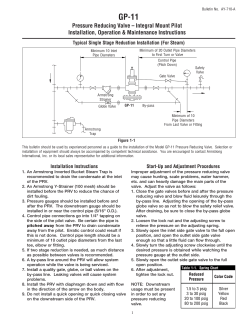
Sectional Directional Control Valve RSQ 240 RSQ 240 is a sectional open center, parallel circuit valve, designed for max. operating pressures up to 350 bar and max. pump flows up to 100 l/min. It is available with 1 to 10 working sections per valve assembly. RSQ 240 is designed with an open center for fixed and variable displacement pumps. The valve is characterized by the unique dual flow range possibility and its ability to facilitate simultaneous operation of several functions. RSQ 240 is available with electrohydraulic or hydraulic proportional remote control, but the valve can also be manually operated. The electro-hydraulic proportional version in particular offers compact design with internal pilot oil supply, solenoids integrated in the valve body and integral hand levers for manual override / manual operation. The valve offers excellent operating characteristics because of the specially designed spools for different applications. Low and uniform spool forces are the result of careful balancing of the flow forces. Q-function The flow control (Q-function) of the inlet section bypasses the major part of the pump flow to tank when the system is idling, still giving access to full pump flow when the services are operated. Besides greatly reducing heat generation this also provides improved operating characteristics. Q-function, in combination with the RSQ 240 unique dual parallel gallery functional principle, and separate flow regulation in each working section, gives this valve a very high performance level. Applications The RSQ 240 is ideal for applications such as truck cranes, backhoe-loaders, excavators, drilling rigs, telescopic load handlers, skylifts, refuse vehicles and fork lift trucks. Technical data Pressure and flow values* Max. operating pressure per port: P1, P2, A, B: PPM: T1, T2, T3, T4: Max. permissible flow on port P1: 350 bar 25 bar 20 bar 100 l/min Further data Spool control force spool control 901: Neutral position: 110 N Max. spool stroke: 130 N Permissible contamination level: Equal or better than 20 / 18 / 14 as per ISO 4406 Viscosity range: 10 – 400 mm2/s (cst) Higher viscosity allowed at start up Leakage A, B → T at 100 bar, 32 cst and 40 °C: ≤ 13 cc/min Pressure fluid: Mineral oil and synthetic oil based on mineral oil HL, HLP according to din 51524 Fluid temperature range: -15 °C up to + 80 °C *Higher values are possible, depending on application. For applications with demands that exceed stated data above, please contact us for consideration. MTTFd value after consultation with HYDAC. Remote control The RSQ 240 is designed with an integrated pilot supply system in order to achieve an easy installation and a reliable remote control function. It is also possible (and in some cases to prefer) to supply the pilot system externally. Further RSQ 240 properties and possibilities zz Complete flow regulation control. At reduced flow the entire spool (lever) resolution is maintained zz Load check valves in each working section zz Spool actuators for external kick-out and spool position sensing zz L. h. and r. h. inlet configurations are available zz Intermediate outlet section for dual circuit systems zz Configurable for systems with variable displacement pump zz Manual versions easily convertible to remote control zz Raised working pressure level in low flow mode allowing increased payloads, for example in cranes zz Pressure relief valve for downstream services zz Separate adjustable flow limitation in each section, independent of pump flow zz Regenerative function zz A wide choice of spools and spool controls for different flow combinations and for several applications and systems zz A full range of service port valves. zz Electrical unloading zz Possibility of high pressure carry-over 31-02-RS240-10 /01.14 Key valve features 1 General overview El. unloading valve Solenoid valve for EHP Two speed control valve Section High pressure carry-over Tie rod Section Main relief valve Weight Inlet section Weight in kg Working section Weight in kg I11D I21A I21B 8.2 6.2 6.1 S11B S11C 5.6 5.5 Outlet section Weight in kg U21A U21B U21C 6.0 5.9 5.8 31-02-RS240-10 /01.14 Dimensions, spool controls 2 Type LA [mm] 901 1001 1101 HP04 HP02 L61 L64 HL61 HL64 LE11 M01 MP03 MH02 MH03 27 64 64 32 70 87 91 87 96 85 LB [mm] 38 70 57 57 Pressure drop Oil temperature / viscosity for all graphs: + 40 °C / 32 cSt ∆p (bar) ∆ p (bar) 10 working sections 10 working sections 1 working section 1 working section Q l/min Q l/min Pressure drop P - T el. unloaded, with PF505, FK501 Pressure drop P - T (idling), with PF505, FK501 ∆p (bar) ∆ p (bar) 10 working sections 10 working sections 1 working section 1 working section Q l/min Q l/min Pressure drop P - T el. unloaded, with PF507, FK502 Pressure drop P - T (idling), with PF507, FK502 ∆p (bar) ∆ p (bar) 10 working sections 10 working sections 1 working section 1 working section Q l/min Q l/min Pressure drop P - T el. unloaded, with PF511, FK505 Pressure drop P - T (idling), with PF511, FK505 ∆p (bar) ∆ p (bar) 10 working sections 1 working section 10 working sections Q l/min Pressure drop P-A/B Q l/min Pressure drop A/B - T 31-02-RS240-10 /01.14 1 working section 3 Dimensions U21B 53 124 116 115 121.5 136 (96.5) I11D 11 13 58 36 48 43 LK L T3 G⅜" TD4 M6 No. of sections 31-02-RS240-10 /01.14 1 2 3 4 5 6 7 8 9 10 4 L [mm] 149 192 235 278 321 364 407 450 493 536 53 100 143 186 229 272 315 358 401 444 487 75 M8 (4x) 22 B-side G½" LK [mm] 217 48.5 42.3 PM G¼" T1 G¾" 39 52 32 20 75 35.5 48 48 T4 G½" 41 47.5 200 47.5 P1 G¾" 16 PPM G⅜" T2 G1" 44 54.5 PS G¼" 44 (107) A-side G½" Dimensions I21A 52 43 U21A 43 48 17 36 129 LK 122.5 L PM G¼" 53.5 LA 25 22 A G½" 24 48.5 42.3 11 6 LK [mm] U21C 10.5 10.5 T2 G1" T4 G½" 24 2 48 31-02-RS240-10 /01.14 PPM G⅜" 12 84 T3 G⅜" 83.5 115 48.5 90 133 176 219 262 305 348 391 434 477 47.5 143 186 229 272 315 358 401 444 487 530 20 47.5 1 2 3 4 5 6 7 8 9 10 P2 G½" Ø 10 H8 L [mm] B G½" LB 33 No. of sections 40 44 44 T4 G½" P1 G¾" Ø 10 H8 40 51 52 T2 G1" 196 47.5 47.5 T1 G1" 5 Inlet section I11D – dual flow ranges 5 4 3 1 4 6 P1 9 8 6 5 7 3 2 7 8 T1 2 9 1 31-02-RS240-10 /01.14 The unique RSQ 240 high-low flow property is achieved by the integral switching spool of I11D, which can be electrically operated by the use of an E926 valve. The I11D with its integral Q-function provides bypass of pump flow to tank in idling condition thereby reducing pressure drop and heat generation, as well as accomplishing improved control characteristics. The bypass flow control spool in combination with an electrical unloading valve (E926) achieves emergency dump of all pump oil to tank. I11D houses a small relief valve cartridge TB12 which together with the bypass flow control spool provides the primary relief valve function of the RSQ 240. A choice of different metering orifice cartridges are available, determining low flow range, influencing pressure build-up to suit different applications and constituting flow from the high pressure carry-over for downstream services. I11D when equipped with a pressure reducing cartridge TRA53, provides pilot oil supply for hydraulic and electro-hydraulic proportional remote controlled working sections. I11D is equipped with a special check valve, FSB4, to cushion the opening of the bypass control spool thereby eliminating unnecessary pressure peaks. 6 1 Inlet type D I11D 2 Main relief valve TB12 3 Bypass flow control spool unit FK401 4 Solenoid valve for el. high-low flow control E926 5 Pressure reducing valve TRA53 6 High-ow flow control spool unit FV401 7 Metering orifice cartridge for low flow PF505 8 Cushioning check valve FSB4 9 Electrical unloading valve E926 Inlet section I21A – single flow range and manually operated sections T1 P1 P2 4 1 3 2 3 PM 2 The I21A provides full RSQ 240 Q-function. When equipped with an electrical unloading valve (E926), emergency dump is achieved. The integral TB12 in combination with flow control spool FK../ TK.. form the primary relief valve function. A number of bypass flow control spools, with its integral metering orifice, are available to suit different system requirements in terms of desired flow from the high pressure carry-over. 1 1 Inlet type A I21A 2 Main relief valve TB12 3 Bypass flow control spool unit TK517 4 Plug PE20 Inlet section I21B – single flow range and remote controlled sections T1 1 P1 P2 6 5 4 4 3 3 2 PM 5 2 1 1 Inlet type B I21B 2 Main relief valve TB12 3 Bypass flow control spool unit FK512 4 Pressure reducing valve TRA53 5 Cushioning check valve FSB5 6 Plug PE20 31-02-RS240-10 /01.14 The properties of the I21B are the same as for I21A, with the addition that it can be equipped with a pressure reducing cartridge (TRA53) providing pilot oil supply for remote control. I21B is equipped with a special check valve, FSB5, to cushion the opening of the by pass control spool thereby eliminating unnecessary pressure peaks. 7 Working section S11B manually operated A B 5 1 2 6 6 5 4 7 3 3 7 4 8 8 2 1 1 Working Section S11B 2 Spool actuator bracket M01 3 Spool 4 Low flow check valve ML24 5 Full flow metering check valve MF24 6 Spool position indicator SM1 7 Port relief / anticavitation valve TBSD160 8 Port relief / anticavitation valve TBSD160 Working section S11C remote controlled A 1 7 B 8 2 7 6 3 5 8 5 9 4 3 4 9 6 10 10 2 1 31-02-RS240-10 /01.14 With cavities for service port valves and for solenoid operated valves for EHP. 8 1 Working section S11C 2 Solenoid valve EHP, 24 V ER64 3 Spool actuator MH02 4 Spool 5 Spool control HP04 6 Low flow check valve ML24 7 Full flow metering check valve MF24 8 Solenoid valve EHP, 24 V ER64 9 Port relief valve TBD160 10 Port relief valve TBD160 Outlet section U21A for manually operated sections T2 2 T4 1 2 1 With cavity for high pressure carry-over plug. Note that the carry-over flow is the flow that is regulated into the center channel i. e. the flow determined by the metering orifice of the inlet section. 1 Outlet section type A U21A 2 Plug P400 Outlet section U21B for remote controlled sections T2 2 1 T3 PPM T4 3 3 2 1 1 Outlet section type B U21B 2 Pilot pressure valve TMB210 3 Plug PMS6 For optimal function it is recommended that port T3 is directly connected to tank and plug PMS6 fitted in TD4. 31-02-RS240-10 /01.14 With cavity for high pressure carry-over plug. With port (PPM) for external pilot oil supply / pilot pressure gauge. With port (T3) for external pilot oil drain (provided plug PMS6 fitted in TD4). The return flow from the spool controls and the pressure reducing valve should be drained directly to tank in a separate piping. With cross drillings for pilot oil supply to B-side of S11C sections. 9 Outlet section U21C – intermediate outlet 2 1 3 T2 T3 PPM T4 3 2 31-02-RS240-10 /01.14 Intermediate outlet allowing dual circuit system. Intended both for manually and remote controlled valves. With cavity for high pressure carry-over plug. With port (PPM) for external pilot oil supply / pilot pressure gauge. With port (T3) for external pilot oil drain (provided plug PMS6 fitted in TD4). The return flow from the spool controls and the pressure reducing valve should be drained directly to tank in a separate piping. With cross drillings for pilot oil supply to B-side of S11C sections. 10 1 1 Outlet section type C U21C 2 Pilot pressure valve TMB210 3 Plug PMS6 Electrical unloading valve and two speed control The electrical unloading valve is a 2-way, normally open, solenoid type cartridge valve. It is an option in inlet sections I11D and I21. It is intended for emergency stop and for pressure drop / heat generation reduction. Data Rated flow: Power consumption: Rated voltage: Max voltage variation: Duty factor*: Connection: Protection class: 40 l/min 17 W 12 or 24 V +/- 15 % 100 % Hirschmann ISO 4400-DIN 43650 IP65 * Sufficient cooling must be secured The unloading valve has manual override. E912 and E926 has push and twist type pin operation. This pin is sealable. PE20 is the plug for the cavity. Codes Push and twist type override 12 V Push and twist type override 24 V I11D E926 for two speed function, high-low flow E926 for el. unloading / emergency stop I21 E926 for el. unloading / emergency stop 31-02-RS240-10 /01.14 E912 E926 11 Spool controls – A-side Spool actuators – B-side Spool control 901 Spool actuator M01 Spool actuator MH02 Spring centered Spool actuator Cap for manuel override Spool control 1001 For valves in standard configuration spool controls are mounted on the A-side of the valve and the spool actuator on the B-side. Detents at positions 1, 2 and 3 Hand lever ME180 Spool control 1101 Spring centering with detent at position 4 Hydr. proportional. For external pilot oil supply. Pilot pressure 6 – 16 bar, max pilot pressure 25 bar* Spool control L61 18 0 The hand lever ME180 is designed to be used in combination with spool actuator MH02, but it is a separate item and must be ordered separately. ME180 provides manual override for EHP controlled RSQ 240 valves. Spool control HP External hydraulic kick-out from inserted spool* Spool control L64 External hydraulic kick-out from inserted and extended spool, locking neutral position* Spool control SM** / SR ** Spool position indicator. Operating range 10 – 30 V. * Connection G ¼" BSP ** Available in connector M12x1 and DT-04 Solenoid valve for EHP – ER62 / 64 Note: If used as “on-off” it is recommended to limit the current by using for example a coupling resistance. Please contact HYDAC for detailed information. ER62/64 ER62/64 are 3/2-way electrically operated pressure reducing valves used to provide controlled pilot pressure to operate valve spools. Functional principle PWM (Pulse Width Modulation) Duty factor 100 % Connection AMP Junior-Power-Timer Recommended PMW frequency 100 Hz Protection class IP 65 Ambient temperature range - 30 °C – + 50 °C Fluid temperature range - 15 °C – + 80 °C ER62 Rated voltage 12 V DC Starting current 500 mA Fully shifted 1,200 mA Coil resistance + 20° 5.4 Ohm 31-02-RS240-10 /01.14 ER64 12 Rated voltage 24 V DC Starting current 250 mA Fully shifted 600 mA Coil resistance + 20° 21.7 Ohm Important: The capacity of the current source must be higher then the current demand of all parallely active solenoids in order to provide the PWM effect. The HG plug is used when the valve is hydraulically remote controlled by a hydraulic servo valve. Spools Open center flow l/min The RSQ 240 spools are available in a variety of flows and styles to accommodate most design requirements. Since the development of spools is a continuous process and all available spools are not described in this data sheet, contact HYDAC for advice on choosing spools in order to optimize your valve configuration. Reduced flow range code 3 PF511 FK505 Reduced flow range code 1 PF507 PF502 PF505 FK501 Pump flow l/min First digit in shaded squares represents reduced flow range code. Second digit represents full flow range code. PF5.. are metering orifices of I11D inlet. FK5.. are flow control spool ( with integral metering orifice ) of I21.. inlets.) How to choose metering orifice: If pump flow is 80 l/min, and wanted reduced speed flow is approx 15 l/min, then metering orifices PF507/FK502 will achieve an open centre flow of 14 l/min. Principle spool matrix Function / Type 10 – 30 30 – 50 50 – 70 50 – 100 Double acting spool / 1 112 114 116 119 Single acting spool / 2 212 214 216 219 Double acting spool with 4th pos. for float / 3 312 314 316 319 Motor spool / 4 412 414 416 419 Spools in reduced flow code 3 (upper shaded area above) are also available. Spools specially developed for truck cranes (also for use in systems with load holding valves), as well as other application adapted spools are available on request. Recommended low flow range: 10 - 30 l/min. 31-02-RS240-10 /01.14 Flow range, l/min 13 Main relief valves Main relief valve TB12 The bypass flow control valve FK.. in combination with the relief valve cartridge TB12 form the pilot operated relief valve function of the inlet sections for the primary circuit. TB12 is adjustable and sealable. zz Setting range: 35 – 350 bar (3.5 – 35.0 MPa) zz Setting range step: 5 bar I11D FKA401/402 ∆p (bar) Q l/min TB12 I21.. FK.. 31-02-RS240-10 /01.14 TB12 14 Service port valves Port relief valve TBD160 The TBD160 is a differential area, direct acting relief valve, for the secondary circuit. TBD160 is adjustable and sealable. Setting ranges for TBD and TBSD160: zz Setting range: 35 – 350 bar (3.5 – 35.0 MPa) zz Setting range step: 5 bar Port relief and anticavitation valve TBSD160 See TBD160 for functional principles. TBSD160 is adjustable and sealable. Relief and anticavitation characteristics Relief characteristics TBD / TBSD160 Anticavitation characteristics TBSD160 ∆ p (bar) Q l/min Q l/min 31-02-RS240-10 /01.14 ∆ p (bar) 15 Service port valves Anticavitation valve SB500 The anticavitation valve service to ensures that, in the event of a lower pressure in the cylinder port than in the tank, oil can be drawn from the system oil tank to the consumer. ∆p (bar) 31-02-RS240-10 /01.14 Q l/min 16 Miscellaneous Pressure reducing valve TRA53 The cartridge type pressure reducing valve TRA53 is used in inlet section I11D and I21B to provide pilot oil supply for remote control. TRA53 is fixed set at 24 bar which consequently is the maximum available pressure level in the pilot system. Pilot pressure valve TMB210 The cartridge type pilot pressure relief valve TMB210, normally set at min 14 bar, is used in outlet section U21B and U21C to secure available pilot pressure build-up for remote control. Depending on system design this necessary starting pressure could also be achieved through downstream arrangements, for example a support leg valve. 31-02-RS240-10 /01.14 TMB210 is adjustable and sealable. 17 Typical hydraulic circuit diagrams For dual flow range. Single Circuit. El. hydr. prop. remote control. 31-02-RS240-10 /01.14 For single flow range. Single Circuit. Manually operated. 18 For single flow range. Dual Circuit. Manually operated. 31-02-RS240-10 /01.14 For single flow range. For systems with variable pump. El. hydr. prop. remote control. 19 Note 31-02-RS240-10 /01.14 The information in this brochure relates to the operating conditions and applications described. For applications or operating conditions not described, please contact the relevant technical department. Subject to technical modifications. 20 Head OfficeIndustriegebiet HYDAC INTERNATIONAL 66380 Sulzbach/Saar GMBHGermany Phone: +49 6897 509 - 01 Fax: +49 6897 509 - 577 E-mail: [email protected] Internet: www.hydac.com
© Copyright 2026 ExpyDoc