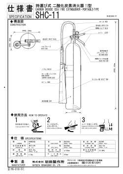
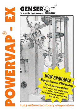
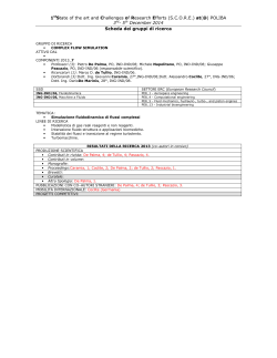
Directional spool valves, direct operated, with solenoid actuation, fast switching RE 23080 Edition: 2014-08 Type WES ▶▶ ▶▶ ▶▶ ▶▶ ▶▶ Size 8 Component series 1X Maximum operating pressure 350 bar [5076 psi] Maximum pressure drop 150 bar [2175 psi] Maximum flow 200 l/min [52.8 US gpm] Features Contents ▶▶ ▶▶ ▶▶ ▶▶ Features1 Contents1 Ordering code 2 Function, section 3 Technical data 4, 5 Voltage and current profile 6 Characteristic curves 7 Performance limits 8 Dimensions 9, 11 Installation bore 10 Project planning information 11 More information 12 3/2-way version Cartridge valve Fast switching, clocked DC solenoid Control using analog amplifiers RE 23080, edition: 2014-08, Bosch Rexroth AG WES | Directional spool valve 2/12 Ordering code 01 02 03 3 WES 8 04 05 06 1X K 07 08 09 A G24 CK50 / 01 3 main ports (P, A, (A1+A2)) 02 Directional spool valve, direct operated, fast switching 03 Size 8 / 10 11 V * 3 WES 8 Symbols 04 N Normally closed P Normally open 1X 05 Component series 10 … 19 (10 … 19: unchanged installation and connection dimensions) 06 Cartridge valve K 07 Fast switching solenoid coil A 08 Direct voltage, clocked 24 V G24 Electrical connection CK50 09 Connection line 5 m [196.85 in] with litz wire 2 x 1.5 mm2 [0.00233 in2] 10 FKM seals V 11 Further details in the plain text * Notice: Symbol representation according to DIN ISO 1219-1. Bosch Rexroth AG, RE 23080, edition: 2014-08 Directional spool valve | WES 3/12 Function, section Directional valves of type WES are solenoid operated directional spool valves with fast switching design. Electrical and hydraulic components are combined in a compact design. They control the start and stop of a flow. The directional valve basically consists of the housing (1), integrated solenoids (2), control spool (3), thread ring (4), mounting plate (5), and a stop bushing (6) with return spring (7). The fast switching solenoid (2) is controlled via a booster amplifier, which supplies a pulse-width modulated voltage and current signal. To achieve the specified values for switching time and flow, the operation must be carried out with a defined current profile (see page 6). Version “N” (normally closed) The force of the solenoid (2) acts on the control spool (3) and pulls it from the rest position to the opened spool position. This enables the direction of flow from P to A1 and A2. After switching off the solenoid (2), the return spring (7) pushes the control spool (3) back to its rest position. Version “P” (normally open) The force of the solenoid (2) acts on the control spool (3) and pulls it from the initial position to the blocked spool position. This blocks the direction of flow from P to A1 and A2. After switching off the solenoid (2), the return spring (7) pushes the control spool (3) back to its initial position. Type 3WES . N... RE 23080, edition: 2014-08, Bosch Rexroth AG 4/12 WES | Directional spool valve Technical data (For applications outside these parameters, please consult us!) General Weight – Valve kg [lbs] 1.2 [2.6] – valve with 5 m cable kg [lbs] 1.9 [4.2] Installation position any Ambient temperature range °C [°F] +20 … +85 [+68 … +185] Transport temperature range °C [°F] –40 … +85 [–40 … +185] Storage temperature range °C [°F] –20 … +50 [–4 … +122] Maximum surface temperature of the valve Service life characteristic value B10-value °C [°F] +85 [+185] (when installed) 1;2) switching cycles 675 million 3) Hydraulic Maximum operating pressure bar [psi] 350 [5076] Maximum pressure drop bar [psi] 150 [2175] Maximum flow l/min [US gpm] 200 [52.8] Hydraulic fluid see table below °C [°F] +40 … +70 [+104 … +158] (HL, HLP) +60 … +70 [+140 … +158] (SAE 40) Hydraulic fluid temperature range mm2/s [SUS] 15 … 46 [69 … 213] (HL, HLP) 35 … 55 [162 … 255] (SAE 40) Viscosity range Maximum admissible degree of contamination of the hydraulic fluid cleanliness class according to ISO 4406 (c) Class 21/19/15 4) Hydraulic fluid Classification Suitable sealing materials Standards Mineral oils HL, HLP FKM DIN 51524 Motor oils Exxon Mobil Mobilgard M440 (SAE 40), Shell Rimula R3+ (SAE 40) FKM Important information on hydraulic fluids! ▶▶ For more information and data on the use of other hydraulic fluids, please refer to data sheet 90220 or contact us. ▶▶ There may be limitations regarding the technical valve data (temperature, pressure range, life cycle, maintenance intervals, etc.)! 1) Surface temperature > +50°C [+122°F] possible, provide contact protection! 2) Operating conditions: integrated in the control block +70°C [+158°F], hydraulic fluid temperature +70°C [+158°F] 3) Observe the seal replacement intervals (see page 11)! 4) The cleanliness classes stated for the components need to be maintained in hydraulic systems. Effective filtration prevents faults and at the same time increases the life cycle of the components. For the selection of the filters see www.boschrexroth.com/filter. Bosch Rexroth AG, RE 23080, edition: 2014-08 ▶▶ The flash point of the hydraulic fluid used must be 40 K higher than the maximum valve surface temperature. Directional spool valve | WES 5/12 Technical data (For applications outside these parameters, please consult us!) Electric Voltage type Direct voltage Limiting performance according to VDE 0580 2) Duty cycle (ED) Switching time according to ISO 6403 W 25 % ≤ 50 (S1 according to VDE 0580) – ON ms ≤ 5 – OFF ms ≤ 5 Maximum switching frequency 2) Hz 10 Protection class according to DIN EN 60529 IP 66 (for professional assembly of the connection line) Thermal class of insulation according to VDE 0580 B Thermal class of enameled copper wire according to VDE 0580 200 Protection class according to VDE 0580 III (protective extra-low voltage) Overvoltage category according to VDE 0580 III Upper limiting temperature of the wire wound coil. Ohmic resistance (incl. 5 m [196.85 in] connection line) °C [°F] < +125 [+185] Ω 0.78 (at +20°C [+68°F] coil temperature) 1.06 (at the maximum admissible coil temperature) Control electronics To achieve the technical data of the valve, the fast switching valve solenoid needs to operate with the following voltage and current profiles 14/12/3 A (boost/pick-up/hold) (see also page 6): Boost voltage (U1) Current V 60 –6 – Boost (I1; peak) A 14 ±1 – Pick up (I2; average) A 12 ±0.5 – Hold (I3; average) A 3 ±0.5 – Hysteresis pick up (I4; peak-peak) A ≤1 – Hysteresis hold (I5; peak-peak) A ≤1 Time pick up (t3) Time decay ms 5 +0.5 – Hold (t4) ms ≤ 0.2 – Idle (t5) ms ≤ 0.4 PWM frequency Operating voltage / pulse voltage Hz freely clocking V 24 ±10 % Electrical connection The valve solenoid is equipped with an electrical connection “CK50” according to the following information. The electrical connection of the solenoid is polarity-independent. The two-core connection line (black) is not exchangeable. Connection line Line cross-section Line diameter Length 2) Operating conditions: integrated in the control block +70°C [+158°F], hydraulic fluid temperature +70°C [+158°F] two-core mm2 [in2] 1.5 [0.00233] mm [in] 7.3/7.9 [0.29/ 0.31] oval m [in] 5 [196.85] Notices: ▶▶ The solenoid coil can only be operated under current control. ▶▶ The booster amplifier is not included in the scope of delivery. RE 23080, edition: 2014-08, Bosch Rexroth AG WES | Directional spool valve 6/12 Control signal → Voltage and current profile Voltage → Current → Valve stroke → Time → t1 Actuation time I1 Current boost (peak) t2 Dropout time I2 Current pick up (average) t3 Time boost (boost phase) I3 Current hold (average) t4 Time pick up I4 Current hysteresis pick up (peak-peak) t5 Time operated I5 Current hysteresis hold (peak-peak) t6 Time decay hold U1 Boost voltage t7 Time decay idle U2 Operating voltage U3 Diode voltage Bosch Rexroth AG, RE 23080, edition: 2014-08 Directional spool valve | WES 7/12 Characteristic curves (measured with HLP46, ϑOil = 40 ±5°C) Pressure differential in bar [psi] → ∆p-qV-characteristic curves – symbol P – P → A (A1+A2) Flow in l/min [US gpm] → Pressure differential in bar [psi] → ∆p-qV-characteristic curves – symbol N – P → A (A1+A2) Flow in l/min [US gpm] → RE 23080, edition: 2014-08, Bosch Rexroth AG 8/12 WES | Directional spool valve Performance limits (measured with HLP46, ϑOil = 40 ±5°C) Symbol P – P → A (A1+A2) Operating pressure in bar [psi] → Flow in l/min [US gpm] → Symbol N – P → A (A1+A2) Operating pressure in bar [psi] → Flow in l/min [US gpm] → Bosch Rexroth AG, RE 23080, edition: 2014-08 Directional spool valve | WES 9/12 Dimensions (dimensions in mm [in]) 1 Cable bushing 2 Connection line, two-core 3 Mounting plate 4 Disassembly bores 5 Outer seal rings 6 Valve mounting screws (self procurement) 4 hexagon socket head cap screws ISO 4762 - M8 x 35 - 10.9 4 hexagon socket head cap screws UNC ASME B18.3-5/16-18UNC x 1-1/2” ASTM-A574 (friction coefficient µtotal = 0.19 to 0.24); tightening torque MA = 41 Nm [30.2 ft-lbs] ±10%, (friction coefficient µtotal = 0.12 to 0.17); tightening torque MA = 30 Nm [22.1 ft-lbs] ±10% each with a washer ASME B18.22.1-5/16-B (type B narrow FBN) Notice: ▶▶ The specified tightening torques are guidelines when using screws with the specified friction coefficients and when using a manual torque wrench. ▶▶ The dimensions are nominal dimensions which are subject to tolerances. RE 23080, edition: 2014-08, Bosch Rexroth AG 10/12 WES | Directional spool valve Installation bore (dimensions in mm [inch]) 1) Depth of fit 7 Contact surface mounting plate LS = Location shoulder Conversion table metric–USA see page 11. Notice: ▶▶ Minimum distance between the valve axes ≥ 65 mm [2.56 in] ▶▶ Minimum distance from the valve axis to edge of installation block ≥ 49 mm [1.93 in] Bosch Rexroth AG, RE 23080, edition: 2014-08 Directional spool valve | WES 11/12 Dimensions: Conversion table (dimensions in mm [in]) Metric USA Metric USA Ø65 Ø2.559 0.01 0.00039 Ø0.25 Ø0.0098 0.02 0.00079 Ø0.05 Ø0.00197 102.5+2 4.035+0.079 Ø48.5+0.3 Ø1.910; 0/+0.0118 93.7+0.2 3.689+0.0079 Ø47H7 Ø1.8504; 0/+0.0010 76.9+0.2 3.027+0.0079 Ø44H7 Ø1.7323; 0/+0.0010 60.1+0.2 2.366+0.0079 Ø41H7 Ø1.6142; 0/+0.0010 14+0.4 0.551+0.0157 Ø38H7 Ø1.4961; 0/+0.0010 48.1+0.3 1.894+0.0118 Ø10 Ø0.394 67+0.3 2.638+0.0118 min Ø4 min Ø0.16 84+0.3 3.307+0.0118 21+1 0.95+0.04 99.5+0.3 3.918+0.0118 25+1 1.10+0.04 53.1 2.091 60 2.362 70.2±0.15 2.764±0.0059 RZ1, RZ3 6.3 RZ1, RZ3 0.248 R0.5+0.2 R 0.0197+ 0.0079 Project planning information ▶▶ The leakage line is to be pre-tensioned with a pressure of 3 ... 5 bar [43.5 … 72 psi]. ▶▶ Characteristic curves and technical data can only be achieved by the defined current profile of the electronic control system (see page 6). ▶▶ The hydraulic system must be completely bled, see data sheet 07600. ▶▶ The connection line is to be fixed at a distance of < 300 mm [11.81 in] from the valve to prevent twisting! ▶▶ The minimum bending radius of 5 x line diameter for the connection line must be complied with. ▶▶ Do not pull on the connection line and valve connector! ▶▶ Do not paint over the name plate! ▶▶ After 2.5 years or after reaching 340 million load cycles, replacing the outer seals is recommended (material no. R961009419). ▶▶ Space required to remove the valve 222 mm [8.74 in] Assembly: ▶▶ Lubricate the outer seals on the valve before installation. ▶▶ Push the valve by hand into the installation bore (see page 10). ▶▶ Tighten the 4 hexagon socket head cap screws (item 6, page 9). ▶▶ After assembly, there must not be a gap between the mounting plate (item 3, page 9) and block! Disassembly: ▶▶ Remove the 4 hexagon socket head cap screws (item 6, page 9). ▶▶ Alternately screw in the 2 hexagon socket head cap screws M5 in the disassembly bores (item 4, page 9) until the valve is released from the installation bore by at least 4 mm [0.16 in]. ▶▶ Remove the valve by hand from the installation bore. Notices: ▶▶ When assembling and disassembling, the data sheet 07600-B must be complied with. RE 23080, edition: 2014-08, Bosch Rexroth AG 12/12 WES | Directional spool valve More information ▶▶ Hydraulic fluids on mineral oil basis Data sheet 90220 ▶▶ Hydraulic valves for industrial applications Data sheet 07600-B ▶▶ General product information on hydraulic products Data sheet 07008 ▶▶ Assembly, commissioning and maintenance of industrial valves Data sheet 07300 ▶▶ Selection of the filters www.boschrexroth.com/filter Bosch Rexroth AG Hydraulics Zum Eisengießer 1 97816 Lohr am Main, Germany Phone +49 (0) 93 52 / 18-0 [email protected] www.boschrexroth.de Bosch Rexroth AG, RE 23080, edition: 2014-08 © This document, as well as the data, specifications and other information set forth in it, are the exclusive property of Bosch Rexroth AG. It may not be reproduced or given to third parties without consent of Bosch Rexroth AG. The data specified above only serve to describe the product. No statements concerning a certain condition or suitability for a certain application can be derived from our information. The information given does not release the user from the obligation of own judgment and verification. It must be remembered that our products are subject to a natural process of wear and aging.
© Copyright 2026 ExpyDoc