Sept. 20, 1927.
v1,642,752
E_ LANDON
PROPELLING DEVICE FOR AEROPLANES
Filed July 15, 1926
Inventor‘,
Elva? Landon) 5?
' Atgorne/yj I
1,642,752
Patented Sept. 20, 192-7.’
UNITED‘ STATES {PATENT ‘OFFICE.
/
ELVIE LANDON, Q1‘ WATEBLOO, IOWA. I
. raornnmne nnvrcn iron. annormnas.
‘ Application ?led my 15,1928.
Serial no. 1223119.
> I
1
My invention relates to improvements in The numeral ‘5'_denotes an annular in-_
‘propelling devices for aeroplanes, and the wardly ?anged bearing member fastened
' object of my improvement is to supply an upon the ,forward wall of the c vsing 2 con
~ incased rotary propeller provided Wit an - centricallyqabout' the forwar aperture 4.
5, adjustable air receiving ?ue or conduit, the Within this member 5iis ?xe a cross plate
' device having means for varying the incli
60
6 having oppositequadrate a crtures, and a
nation of the conduit relative to’the casing, damper vplate 7 is mount '
and other means for regulating the amount 'rockingly in said member 5 in advance of
a the ?xed plate 6, and of like shape and pro
of air current traversing ‘the device.
vided with a handle 8, whereby the plate _7 05
This
"object
I
have
accomplished
b
the
~10,
may
be rocked to vary the width of opening /'
means which are hereinafter describe and
claimed, and which’are illustrated in the of the apertures in the plate 6, to thus gov- v
'
_
__
rotatably
or
'
accompanying drawings, it being understood ’ cm the quantit of air passing through the
- that minor changes or modi?cations of the casing 243 an conduit 16.
‘15 structures shown may be made within ‘the
SCtiPG of said claim.
7
p
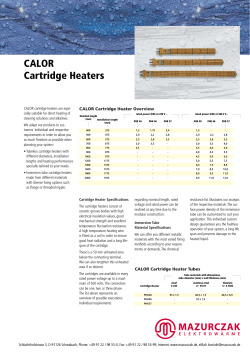
11 said drawings, Fig.1 is a central hori
.
The conduit 16 maybe swung adjustingly 70
by any appropriate means, the means shown ‘ ‘
being merely illustrative ‘of one type there
- zontal longitudinal section of one of my for. Staples or loops 17 may vbe fixed on op
20
posite parts, quadrately, of said conduit 16 ig. 2'is a rear elevation of the propeller to receive looped ends of cables, such as 78
casing and of the adjustable air current shown at 18 and 28 on opposite sides, and at
‘propelling devices, with‘ parts broken away.
re ulating means thereon.
,-
'
29 at points ninety degrees apart from the
he numeral 2 denotes a hollow cylindri ?rst-mentioned cables. These cables are car
cal casing whose rear art is curvilinearly riod over sheaves 19 rotatably mounted upon
25 diminished at 3, provi ing an air piercing the. casing 2 near its junction with "its di so
end to diminish frontal pressure. vThe ?at minished ‘part 3, thence being carried over
forward wall of the casing 2 has a central other sheaves such ‘as 20, or 3(l—31 respec- '
aperture 4 traversed bythe rear part of a, tively to be end connected to opposite vparts
propeller rotary shaft 1 which may be ro of the annular grooves of the winding-drums
S0 tated by means of any suitable motor not 21 and 32 respectivel .1 Each winding drum
shown. The rear end of this shaft within 'has an operatin ra ial handle 22, and each
‘ the casing is ‘rotatabl mounted in a bearing . has a‘ connecte
ratchet-wheel as at 24 and
sleeve 10 integral with a supportin cross 33, the same being rotatable; on short ?xed
bar 9 'whoseoposite ends are bolte to the shafts as at 23 rojectin 'at/di?‘erent angles
relative to eacli other rom a support 35.
lindrical part of the casing, ?xed on said Each ratchet-wheel has a pawl as at 25 and
shaft 1, is mounted a hub 11 carryin radial ‘34, pivoted on said support 35 and havin
j. opposite walls of the casing. Within the cy
vanes '12 set obliquely relatively to t e shaft
to function as propeller vanes. The outer
'
.40 end parts
of'the‘vanes 12 are preferably
curved‘ in the direction of rotation of who
an arm 26-with a spring/connection 27 wit
said‘ support, tending to keep each pawl in
engagement with the teeth of the ratchet
wheel, the teeth. being symmetrically anti
shaft except that these parts are curved with clinal, so that the pawl end may slip either . _ ‘
the ‘same obliquity'as' the stem parts of the way releasably over-‘the teeth when the .
wheel’ is rotated in either direction. y
‘I The rear part 3 of the diminished casing ' In the operating of the device as part of 100‘
is open and‘ provided on opposite walls, that the ropelling mechanism of an aeroplane
er apparatus for which it is adaptable, '
is, without and within,’_with~ annular bear .or'ot
‘the.
operator
may by use of» the windingv
ing members 14 and 13 whose inner bearing
‘drums
21
and
32, operated either singly or
7
surfaces for-in a ‘zonal spherical bearing sur-l
‘0 face for an‘inner‘ zonal bearing member 15, jointly, according to'the shift of direction
' whose rear end. is fastened around the for of the. conduit 16 to be obtained, rock either
ward open end of a tubular air conduit 16, or both in a way‘ to, by means of the cables
so that theconduit is thus mounted for lim? connected to the conduit, swin the conduit
vanes.
v
,
"
fited universal swinging adjustments upon ‘to any an 1e relative to the axis of the pro 110
peller, wit in thelimits provided for it.
.5 said casing.
1,642,752
This adjustment of the conduit is to di
Having described my invention, what I
rect it in the direction which is to be given claim as new, and desire to secure by Let
the aeroplane, so that the ejected air Wlll ef-‘ ters Patent, is:
fect jet, propulsion in action as the aeroplane
In a device of the character described, a
its manipulated for changes of direction, as cylindrical hollow casing having a closed
the shift in the conduit should be one which rear head with a central delivery port con- .
is accommodated to the direction to be taken taining spaced segmental closure plat-es, ro~
by the aeroplane.
-
tatable segmental damper plates mounted on
.
The means for shifting the conduit may the casing to variably close the interspaces
'10 be other than those shown, and the relative of the ?rst-mentioned closure plates, the for
dimensions of‘ the conduit and the casing, ward part of the casing being gradually ' '
as of the propeller vanes, may be varied as diminished and terminating forwardly in a
I may benecessary for use on different species
hollow spherically segmental joint member,
of aeroplanes, in which eitherspeed. of move a tube projecting forwardly from and hav
ment‘, or weight carrying‘capacity are the ing a rear‘ spherically segmental joint mem
ber mounted in the ?rst-mentioned joint
The air governing damper device 6—7 is ‘member, pawl-‘controlled ratchet-wheel car
determiningfactors-q
‘
1
-
>
'
,
'
rying’ winding-drums ?exible connections
current through the casingv under varying between said winding-drums and parts of the
' ‘to be used I or regu ating the amount of air
,_ n
conditions of use, and the damper‘part 7 may said tube spaced circumferentially ninety
, be vactuated by means of other appliances degrees apart, and an air-propeller device
than the hand e 8 if desired.‘ The said pro rotatably mounted in vsaid casing centrally.
. pelling device _may be'positioned upon the
aeroplane accordine' to‘the necessities arising
from differences OtPCODStI‘HCtIOII thereof.‘
In testimony whereof I a?ix my signature.
" ELVIE LANDON.
© Copyright 2026 ExpyDoc