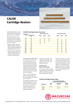
March 15, 1966
F. E. RAY ETAL
3,240,425
RELATIVELY SMALL CASING FOR A HIGH SPEED MINIATURE GENTRIFUGE
Filed June '7, 1962
5 Sheets-Sheet 1
INVENTORS
FPA'D 5. PA/
BY
£M/z ,4. sea/@0429;
651E440 M 14/04/727
5 40 %/ JMW/ Z”,
March 15, 1966
3,240,425
F. E. RAY ETAL
RELATIVELY SMALL CASING FOR A HIGH SPEED MINIATURE CENTRIFUGE
Filed June 7, 1962
5 Sheets-Sheet 2
256
250
248
42
FIG‘. 3
March 15, 1966
F. E. RAY ETAL
3,240,425 -
RELATIVELY SMALL CASING FOR A HIGH SPEED MINIATURE CENTRIFUGE
5 Sheets-Sheet 3
Filed June '7, 1962
,
mum!"
62/
L
FIG‘. 5 9’
126
(DQU MM“7 204mmjpW?WWW
0
BY
5/?7
C, adNVmm
March 15, 1966
3,240,425
F, E, RAY ETAL
RELATIVELY SMALL CASING FOR A HIGH SPEED MINIATURE CENTRIFUGE
Filed June 7, 1962
5 Sheets-Sheet L
QNN
E:‘Q
NWWW
/7 / . /
5
_
. _____
Q‘\\
Qb
INVENTORS.
[95D [- PAY
EM/[ /4- .s‘CaRDATO
March 15, 1966
F. E. RAY ET AL
3,240,425
RELATIVELY SMALL CASING FOR A HIGH SPEED MINIATURE CENTRIFUGE
Filed June '7, 1962
5 Sheets-Sheet 5
“3
F76. a
\
WI" I 250')
M
99
@@
/
i
l
l
J,A!
I
HIIlH
/60
34
/96
\\\Q\
~50
—30.
’ 92
INVENTORS.
F250 6. A24 y
BY
6114/4 ,4. scaeanra
6£1€440 14/, 14/04::
W ‘ a“, £44m MZQ
47702/1/575
United States Patent 0 "ice '
3,240,425
Patented Mar. 15, 1966
1
2
3,240,425
for example, in prothrombin and coagulation time deter
mination, the centrifuge module would be employed for
purposes of providing pure plasma from whole blood,
Fred E. Ray, Ramsey, N.J., Emil A. Scordato, Bronxville,
1\_LY., and Gerald W. Wolfe, Santa Monica, Calif., as
and a coagulation timer module may conveniently be
utilized therewith to detect initial clot formations follow
ing the introduction of a sample of the plasama into a
RELATIVELY SMALL CASING FOR A HIGH SPEED
MINIATURE CENTRIF‘UGE
slgnors to Becton, Dickinson and Company, Ruther
ford, N.J., a corporation of New Jersey
Filed June 7, 1962, Ser. No. 200,739
10 Claims. (Cl. 233-1)
This invention relates to a centrifuge casing and, more
particularly, to a casing for a relatively light weight,
miniature centrifuge capable of rotating at high speeds
separating liquid materials into their constituent parts
Within short periods of time.
In centrifuging liquid materials for separating into con
particular chemical reagent.
A casing for a centrifuge constructed in accordance
with the teachings of the present invention includes a
10 base from which extends vertically, in an upward direc
tion, a body having four side walls de?ning a parallelo
gram in cross-section. A pivotal cover is hingedly
mounted on the body from a closed position at which cen
trifugation is intended to occur to an open position to
15 provide access to the casing interior. Thus, in the latter
case the intended operation may be accomplished whether
trifugal forces of magnitudes capable of causing the de
it be loading and unloading of a centrifuge head with
liquid material, removal or remounting of the centrifuge
head, or the performance of any maintenance or repair
sired separation. The head would normally be driven at
work as needed.
stituent parts, a rotating head may be provided for re
ceiving the selected liquid material to subject it to cen
relatively high speeds; and numerous safety precautions
Within the casing a relatively high speed motor is
are required in order to protect attending personnel.
Incident to centrifuge use, safety precautions should be
present not only during actual centrifugation, but at all
times, including protection when the centrifuge is in non 25
use; therefore, measures should be taken to assure only
securely mounted in a manner to be substantially free
from vibration and, at the same time, su?iciently isolated
to dampen and even prevent induced vibrations during
motor operation. A centrifuge head is coupled with the
outputshaft of the motor through a releasable locking
deliberate initiation of operation of the centrifuge. At
the same time, the construction of the centrifuge should
mechanism which permits removal of the head and re
mounting as desired. In this connection, the casing
be such to facilitate the introduction and removal of the
includes a pressure plate therein to facilitate the actuation
liquid material prior to and subsequent to operation, re 30 of the releasable locking mechanism when the cover is in
spectively.
Furthermore, the rotating ‘head should be
readily removable for maintenance, as well as cleansing
operations. It is also desirable to permit the liquid ma
terial to be viewed during centrifug-ation to observe the
separation taking place.
Needless to say, provisions
should be made to prevent accidental release during cen
trifugation of the liquid material to be separated. Pre
cautionary measures should be taken to prevent uncon
trolled separation during centrifugation which may result
in throwing or splattering of the material being subjected
to centrifugal forces.
It is, therefore, a principal object of the present inven
tion to facilitate the foregoing by providing a casing for
an open position to enable the head to be removed without
dif?culty.
.
The cover, as stated, is pivotally hinged to the casing
body and, under these circumstances, is adapted to be
latched securely in its closed position over the body side
walls. To this end, a latch assembly is provided between
the cover and the body and includes interengaging parts
capable of the latching function. An arm projects out
wardly from the cover and is adapted to be manually
40 actuated to release the latch when it is desirable to pivot
the cover to its open position.
When the centrifuge head has been loaded with the
material to be separated and the cover placed in its closed
a centrifuge which permits the centrifuge to be com
position, a shiftable pressure bar, constituting part of the
pactly incorporated therein within detrimentally affecting 45 casing will be in engagement with an interiorly mounted
the intended centrifuge operation and, at the same time,
start-stop switch for the motor and adapted to be de
provide a portable miniature structure.
pressed to energize the motor. A rather inaccessible
Another object is to provide a centrifuge casing having
switch is incorporated in the casing body for closing and
means for assuring the initiation of operation of the cen
trifuge only at such time as the centrifuge is properly
loaded with the liquid material to be separated and pos
breaking the circuit of the motor and its switch. In this
connection, projecting portions of the cover are adapted
to close the safety switch only when the cover is in its
sessing a protective enclosing position at which, and, only
closed latched position for assurance against inadvertent
at which, the centrifuge operation will commence.
Still another object is to provide a centrifuge casing
having means for cooperating with the centrifuge for
facilitating the detachment and complete removal of the
actuation of the motor switch.
The cover and body are also interconnected with a link
centrifuge head.
A further object is to provide a centrifuge casing having
means for initiating the operation of the centrifuge, only
when intended.
A still further object is to provide centrifuge casing
having means for positively enclosing the centrifuge head
and, at the same time, enabling it to be readily accessible
assembly which permits the cover to be readily pivoted
from its open to closed position, but will prevent the cover
from extending beyond a certain point as it approached
the desired open position. The cover is also provided
with a transparent cap which perm-its the centrifuge
operator or attendant to view the centrifuge head and its
contained liquid material to be separated during cen
trifugation. In addition, this cap acts as a shield in com
pleting the encasement of the centrifuge within the casing.
to permit introduction of the material to be separated
The casing, with contained centrifuge is relatively com
and removal of its separated constituents following cen 65 pact requiring a minimum number of parts, all of which
trifugation.
lend themselves to portable, light-weight miniaturization
A principal object of the present invention is to provide
without sacri?cing effective high speed centrifugation
a centrifuge casing having means for enabling the cen
within a minimum of time. The casing is so constructed
trifuge to be employed as a module, singly or together
to serve as an individual module readily coupled With a
with other units, capable of similar modular use whether 70 second centrifuge also of modular form. On the other
they be another like centrifuge or a functionally distinct
hand, the centrifuge module may be part of a system of
unit, all of which may contribute to a desired result; as
modular units conveniently arranged and coupled with
3,240,425
3
4
respect to one another, as well as designed to provide.
centrifuge permits physicians to utilize it at the bedside
maximum arrangement and ?exibility depending upon
of a patient.
the, intended use and application.
The centrifuge head assembly 16 is provided with a cav
ity for the reception of whole blood. Upon rotation of
As will be explained in detail, a preferred application
of the centrifuge is in prothrombin time determinations
and measurements of coagulation properties of plasma in
the head, the contained blood will be exposed to cen
trifugal forces. The heavier red and white blood cells
diagnostic and therapy control. With this in mind, a
and platelets under these circumstances will separate from
laboratory or clinic for such purposes may be comprised
the lighter plasma of the blood. After a given period of
of modular units readily coupled with one another which
rotation, separation will be complete. The head speed is
may also include a coagulation timer and heater block 10 then reduced through the de-energization of the motor 18.
forming part of a laboratory. In view of the modular na
Shortly thereafter shiftable means within the head assem
ture of the system, the individual modules can be em
bly 16 will react to the reduction in centrifugal force to
ployed whether the laboratory be large or small. Fur
seal off a major portion of the pure plasma from the
thermore, the miniature size and portable nature of the
heavier blood constituents. The sealed relationship sub
individual modules, of which the centrifuge forms a part,
sists after cessation of rotation such that the lighter con
can be carried and most advantageously utilized by any
stituents, notably plasma, may now be removed through
physician at a patient’s bedside.
.
,
the use of conventional aspirating devices.
Other objects and advantages will become apparent
In order to reload the centrifuge the separated blood
from the following detailed description which is to be
need only be removed. In this connection, a disposable
taken in connection with the accompanying drawings il 20 bag may be utilized to contain the blood within the head
lustrating a somewhat preferred embodiment of the in
cavity. Thus, after separation, the bag with separated
blood would be removed and replaced with a fresh bag
vention, it being understood, however, that the scope of
the present invention is not necessarily limited thereby.
into which a new sample of blood to be separated is in
I FIG. 1 is a perspective view of the casing of the pres
troduced. The centrifuge operation may then be re
ent'invention having mounted therein a centrifuge shown
peated on the fresh blood sample. As disclosed in the
in association with another like unit illustrating the ver
companion application, the head assembly would meas
satility of the modular system contemplated, with one of
ure approximately 11/2 inches in diameter; and the ca—
the centrifuge units coupled with a coagulation timer
pacity of the bag would be in the neighborhood of a few
shown in phantom;
milliliters.
' FIG. 2 is another perspective view of a casing of the
present invention mounting a centrifuge, with the cover
The releaseable locking assembly 20 permits the head
assembly 16 to be quickly disconnected from the output
of the casing shown in a partially opened position;
shaft of the motor 18 and, at the same time, enables
FIG. 3 is an enlarged elevational View, sectioned
the head to rotate with the shaft during operation. The
through the casing, with the cover in a closed latched posi
locking assembly includes, among other parts, a radial
tion with certain parts broken away and removed for 35 ?ange 22 which may be engaged and shifted downwardly.
clarity;
FIG. 4 is a sectional view taken along the line 4—4 of
FIG. 3;
FIG. 5 is a sectional view taken along the line 5—5 of
FIG. 3;
FIG. 6 is a fragmentary sectional view taken along line
6—6 of FIG. 5, showing the link assembly in open posi
tion, with its closed position being shown by way of
dotted lines;
As disclosed in the above application, this would have
the effect of unlocking the headrassembly 16 and thereby
permit it to be lifted off the drive shaft.
Since one of the primary uses of the centrifuge 10 is
to provide pure plasma quickly and conveniently for test
procedures to follow, the motor 18 should be capable of
high speed output. For this reason the speed capabilities
of the motor 18 will range from about 15,000 to 20,000
rpm.
FIG. 7 is a fragmentary sectional view taken along line 45
Referring now to the casing 12, it will be observed
7——7 of FIG. 5, showing the safety switch with associated
that the centrifuge 10 is conveniently accommodated
casing structure,
therein for e?icient operation. Thus, the casing 12 in
FIG. 8 is a fragmentary sectional view taken along
cludes a base 24 on which the motor 18 rests. A body
line 8-8 of FIG. 3 showing the cover latching assembly;
25 is anchored to the base 24 and includes upwardly ex
and
50 tending vertical side walls 26 and 28, front wall 30 and
‘ FIG. 9 is a fragmentary sectional view taken along line
9_—'-9 of FIG. 3 showing the motor mounting.
rear wall 32.
A cover 34 is pivotally mounted on the
In the drawings, a centrifuge 10 is shown disposed with
in a casing 12 in accordance with the teachings of the
present invention. As depicted in ,FIG. 1, a modular
body 24 from a closed position at which the centrifuge
10 is operated to an open position at which the centri
system is contemplated whereby the casings, together
with their contained centrifuge, may be disposed side by
tion, the .material to be separated may be introduced into
fuge is preferably inoperable. Thus, in the latter posi
the centrifuge head assembly 16 and following separa
tion through centrifugation, the material may be re
side for operation, together with a further modular unit
14 in accordance with the dictates of the particular system.
moved therefrom. When the cover 34 is in its open
'_ The centrifuge 10 may be of a type, which includes a 60 position, the head assembly 16 may also be advantage
centrifuge head assembly 16 releasably anchored to a
ously removed through the actuation of the locking
relatively high speed motor 18 by means of a locking as
assembly 20 to permit cleansing, maintenance or repair
sembly 20. The details of construction and operation of
if needed.
the particular centrifuge 10 are disclosed in companion
The base 24, under the circumstances, will include a
patent application entitled Improved Centrifugation Ap 65 vertical
front panel 40 and vertical rear panel 42 both
paratus and Method, ?led on May 7, 1962 under Serial
of which are integral with a substantially horizontal
No. 192,709 in which a common interest is present. Suf
wall 44 having an elevated wall portion 46. The wall
?ce it to say that the centrifuge 10 is of a reduced size
portion 44 is provided with a bore 48 and enlarged co
rendering it conveniently portable. One of the applica
axial counter-bore 50 for receiving downwardly pro
tions of the centrifuge 10 is in the area of blood separa
jected parts of the motor 18. A series of resilient pads
tionfor prothrombin time determinations and measure
52 may be strategically located on the bottom of the
ments of the coagulation properties of plasma in di
base at favorable locations to provide a cushioning effect
agnostic and therapy control. Thus, the centrifuge 10
and, at the same time, preventing marring of the surface
would be of advantage in clinical and medical laboratory
use. The relative ease in handling and carrying the 75 on which the casing is placed.
3,240,425
6
5
A number of screws 56 extend through the base 24
and threadedly engage with openings in the body 25 to
secure these parts to one another. In this connection,
a resilient grommet 58 extends around openings 60 in
the base 24 through which the screws 56 project. As
will be appreciated, these grommets 58 are employed
for purposes of minimizing surface to surface con-tact of
The plate 110 is biased vertically by means of a pair
of springs 128 extending between the bottom surfaces of
the plate 110 and upper face of the plate 90. Screws
121 project through each of the springs 128 into threaded
openings 124 in the plate 90. Cylindrical spacers 126
surround each of the screws and rest on the upper face
of the plate 90. The spacers also engage with washers
128 disposed between the head of the associated screw
and the upper face of the plate 110. Thus, it will be
tions therebetween. A cylindrical spacer 62 surrounds
the threaded shank of the screw 56 and is adapted to 10 apparent that the spring will bias the plate 110 in an
upward direction away from the flange 22 and, at the
engage with the screw head as well as surfaces of the
same time, will limit the amount of vertical movement
plate 74. Accordingly undue penetration of the screw
of the‘ plate 118 to assure adequate spacing between the
56 into the plate 74 is prevented, as well as possible
these parts and, consequently, the transmission of vibra
damaging compression and distortion of the grommet 58.
The motor 18 includes the usual downwardly extend
ing anchor bolts 66 which are adapted to project through
suitably formed openings 68 in the wall 44 of the base
plate and the ?ange 22.
The plate 118 is also pivotally mounted on pin 130
24 when the motor is seated thereon. Mating nuts 78
engage with the threaded bolts to completely anchor the
space the associated sides of plate 110 from these ?anges.
A switch 134 is suspended on the plate 98 by means
secured to ?anges 98 and 99 of the rear wall 32.
Spacers 132 are mounted on the pin 138 and serve to
of a suitable mounting bracket 136 so that its actuation
motor 18 to the base 24.
tially rectangular and planar in con?guration. These side
pin 138 extends vertically and projects beyond the upper
face of the plate 98. As will be explained shortly, the
walls are spaced from one anotherin substantially par
allel relationship and are interconnected by means of an
actuation pin 138 is adapted to be depressed, thus ener
gizing the motor 18 when the cover 34 is in its closed
The side walls 26 and 28 of the body 25 are substan
integral transverse plate 74 extending therebetween. The
plate 74 is provided with a corresponding number of
tapped openings 76 for threadedly receiving the screws
56 in anchoring the base 24 to the body 25. The plate
74 is also provided with an adequate size opening 78 for
suf?ciently clearing surfaces of the motor 18. A fuse 30
holder 80 may be carried by the plate 74 to mount a
suitably rated fuse for the motor 18. In this connection,
the elevated wall portion 46 of the base 24 may be
supplied with an adequate opening 82 for the insertion
and removal of a fuse.
The front wall 30 and a rear wall 32 are likewise sub
stantially planar and spaced from one another in parallel
relationship. A horizontal plate 90 extends transversely
therebetween and is integrally formed therewith for main
taining this relationship. In addition, inwardly extend
ing integral enlarged corners 92 are situated along each
of the respective vertical edges of the front wall 30 and
position.
A safety switch 144 is also mounted within the casing
12 and serves to maintain the circuit of the motor 18
and switch 134 open until such time as the cover 34 is
in its latched and closed position. To this end, the
switch 144 is mounted by an angle bracket 146 :so that
its actuation button 148 projects through the bore 158
of the plate 90. ‘In order to protect the button 148 from
inadvertent contact and assure energization of the motor
18, only when the cover 34 is closed, an upwardly pro
jecting rim 152 surrounds the upper end of the button
148. A downwardly projecting pin 154 on the cover
34 is adapted to be aligned with the button 148, and
subsequently depress it to actuate the switch 144 as the
cover 34 is lowered to its closed position.
Referring now to the cover 34, it will be observed
that a generally ?at planar panel 160 extends into a raised
con?guration de?ned by four trapezoidal shaped inclined
panels 162, 164, 166 and 168, whose trapezoidal walls
are integral and symmetrically disposed. The upper pe
provided with a tapped opening 94 for mating with screws
96 also extending through suitably countersunk openings 45 riphery of these walls is integrally connected by means
of the substantially horizontal panel 170 which may
97 of the plate 74 for interconnecting the body side
rear wall 32 below plate 90.
walls.
These corners are each
The rear wall 32 above plate 91) is provided
possess a slight curvature, as shown.
The cover 34 is pivotally mounted on the body 25
with integral ?anges 98 and 99 extending inwardly there
by means of an elongated hinge pin 184 having its ends
from. The plate 90 includes an enlarged opening 188
for accommodating, with su?icient clearance, the upper 50 ?xed in the side walls 26 and 28 of the body 25. The
panel 168 is formed with a somewhat rectangular central
part of the motor 18. The plate 90, along the periphery
cutout portion 186 embraced along two opposed edges
of this opening, is formed with a downwardly projecting
by side panel portions 188 and 190, both of which ter
rim 102 having a somewhat conical inner face 164. A
minate at their free ends in enlarged tubular portions
192 and 194, respectively. These enlarged tubular por
tions are respectively provided with apertures 196 and
to be interposed therebetween to mechanically isolate
198 which are adapted to freely receive the hinged pin
the motor from plate 90 and, at the same time, reduce
184. Under these circumstances, the cover 34 is adapted
vibration incident to motor operation.
to pivot about the pin 184 from its open to closed position.
As mentioned in the foregoing, the present invention
contemplates means for facilitating the depression of por 60 With respect to the open position, a link assembly 280
is incorporated into the structure to limit the extent to
tions of the releasable locking mechanism 28 in order
which the cover 34 may be pivoted when opened. Ac
that the head assembly 16 may be removed once the
cover 34 is in an unlatched open position. This assumes
cordingly, link assembly 200 includes an arm 202 having
the form of a pressure plate 110 having downwardly
one end pivotally mounted to the cover by means of the
extending peripheral apron 112. An opening 114 is 65 pivot screw 204. The threaded shank of which is dis
formed in the plate and is of a size sufficient to clear sur
posed in a tapped opening 206 of the downwardly project
faces of the locking mechanism 20. The circular sym
ing ?ange 207 of the cover 34. A preloaded spring 208
metry of the opening 114 is interrupted by a pair of
between the associated end of the arm 202 and head of
radially inwardly extending tongues 116 also clearing
the screw 204 serves to supply resistance to the pivotal
surfaces of the locking assembly 20; but at the same 70 movement of the cover 34 to the extent that the cover must
be deliberately shifted in its full traverse from open to
time, these tongues are however adapted to engage with
closed position and back again. The other end of the
the radial ?ange 22 thereof when the plate 114 is de
pressed upon the application of pressure in a downward
arm 202, on the other hand, is pivotally mounted on the
inwardly extending ?ange 98 of the rear wall 32 by means
direction, to correspondingly shift the associated parts
of a headed pivot pin 210. This pin 210 together with
of the locking mechanism 20.
space is accordingly provided between this face and sur
face of the motor 18 so that a resilient ring 106 is adapted
Y
3,240,425
7
8
its head is adapted to ride in the elongated double slot
212 of this ?ange; and the slot 212 is of sufficient length
tion at which arm 202 will rest on stop pin 220.‘ An elec
trical connection between the female plug 266 and a
source of electrical energy will be assumed throughout
to permit this movement of the pin throughout the full
pivotal movement of the cover from open to closed posi
tions. An interposed resilient washer 214 acts as a spacer
and facilitates the intended movement of the associated
end of the arm 202 and pin 210.
The amount of movement of the cover 34 as it ap
this discussion. While the centrifuge 10 may be employed
in the centrifugation of various liquid materials and solu
tions, it is particularly applicable to the separation of
blood. In this connection the centrifuge is adapted to
provide pure plasma quickly and conveniently for test
ing as, for example, in prothrombin and coagulation time
proaches its open position is limited by means of a stop
pin 220 which is adapted to engage with the arm 202.
This pin projects from the panel 160 of the cover and may
determinations. With this in mind, a measured quantity
of whole blood is now introduced into the centrifuge
be adjusted depending upon the desired open position for
head 16 in a manner which may assume that disclosed in
the cover 34 which, in the disclosed embodiment, ‘would
result in the panel 160 being in a substantial horizontal
the above referenced companion patent application. In
position.
would be in the order of approximately 2 ml. After the
this connection, the measured quantities contemplated
centrifuge head 16 has been properly loaded with the
selected blood sample, the cover 34 is then pivoted to its
closed position about the pivot pin 184. The lips 230 and
sembly 226 is conveniently interposed between the body
233 Will accordingly engage and latch the cover in place.
and the cover. Thus, a vertical plate 223, having a lip
230, is secured in the vertical leg of an angle bracket 232 20 Simultaneously with the latching of the cover 34, the pin
154 will depress the actuating button 148 of the safety
anchored to the plate 90 of the body 25. A suitable
switch 144. The motor 18 is now energized by merely
slotted opening 234 is provided in the pressure plate 110 to
pressing downwardly on bar 260 to depress the pin 138
permit the latch plate 228 to project therethrough. A
to close the switch 134 and, consequently, complete the
latch plate 236, having a lip 238, is pivotally mounted
within the cover 34 by means of a pair of pivot pins 240 25 circuit to the motor. The head 16 will immediately begin
and 242. A pair of spring plates 244 and 246 are secured
its period of rotation. As the head 16 rotates, constituents
of the blood possessing higher speci?c gravities will move
to the latch plate 236 at one end, with their ends being
radially outwardly and replace those of lower speci?c
bent to facilitate engagement with the inner face of the
gravity. The heavier red and white blood cells and
trapezoidal wall 166 of the cover 34. An arm 248 extends
transversely from the latch plate 236 in an outward direc 30 platelets will accumulate at the radial periphery of the
cavity, Whereas the much lighter plasma will predomi
tion through a conveniently located slot 250 in the
In the closed position the cover 34 is adapted to be
latched to the body 25; and, with this in mind, a latch as
trapezoidal wall 166. Accordingly, when the arm 248 is
shifted inwardly and the cover is in its closed position, the
engaging lips 230 and 238, which are otherwise latched,
will be forced out of engagement against the bias of the
springs 244 and 246. The cover 34 at such time need only
be lifted and then pivoted to its fully open position at
which the arm 202 will come to rest against the stop pin
220. When the cover 34 is to be shifted back to its
closed position, the engaging lips 230 and 238 will re
latch as the plate 236 cams against plate 228 under the
bias of the springs 244 and 246.
The cover is additionally provided with a somewhat
circular central opening 256 in its top panel 170. A
transparent cap 258 formed from a suitable resinous ma
terial such as Lucite is secured across this opening to per 45
mit the centrifuge user or attendant to view the liquid
contents of the head 16 during centrifugation.
As mentioned in the foregoing, means are conveniently
located as part of the cover 34 to facilitate the actuation
of the switch 134. In this connection, a pressure bar 260
is also pivotally mounted on the pin 184. When the cover
34 is in its closed latched position the bar 260 will be
substantially co-planar with the cover panel 160 and co
incidentally, will have its under face resting on the actu
nate the inner central con?nes of the cavity.
After a
given period of rotation, when complete separation has
occurred, the motor 18 isdeenergized, thereby resulting
in deceleration and reduction of the rotational speed of
the head 16. The point at which the motor is deenergized
may be ascertained by viewing this separation through the
transparent cap 258 and then depressing the bar 260 to
open the switch 138 and thereby the circuit to motor 18.
On the other hand, the cycle may be governed by con
veniently located timing means either incorporated Within
the casing 12 or located exteriorly thereof. As disclosed
in the above identi?ed application, the plasma is sealed
from the heavier blood constituent upon the diminution
of the centrifugal’ force incident to deceleration. This
sealed relationship will continue after the head rotation
has stopped. It has been found in the embodiment of
the invention under consideration, that the complete cen
trifugation cycle for whole blood will take between 15 to
20 seconds for satisfactory results to be realized.
When the head 16 has come to a complete stop the cover
34 is unlatched by pressing inwardly on the arm 248 to
disengage the lips 230 and 238 of the latch assembly 226.
The cover 34 is then pivoted about its hinge pin 184 to its
fully open position, at which the link arm 202 rests on the
ation pin 138. Thus, the attendant need only apply pres 55 stop pin 220.’ At this point the pin 154 will now be re
sure to the bar 260 to depress the pin 138 to actuate the
switch 134 and consequently energize motor 18. As will
be appreciated, this bar 260 will remain in this position
resting on the pin 138 notwithstanding the unlatching of
the cover 34 and pivoting it to its fully open position.
The modular aspects of the present invention are most
moved from engagement with the switch button 148 to
open the safety switch 144. The pure plasma may now
be applied particularly for test purposes by merely remov
1ng the desired quantities from the containing cavity of
the centrifuge head 16 by employing conventional devices
which may include syringes, pipettes, and the like.
effectively attained by locating a female electrical plug 266
When it is desired to reload the centrifuge in order to
and male electrical plug 268 on the body side walls 26 and
perform another separation, the already separated blood
28, respectively. Each of these plugs 266 and 268 are
would ?rst be removed from the centrifuge head cavity
secured in place by means of a retaining ring 270 and 65 and replaced by a fresh blood sample. The centrifuge
bracket 272 anchored to the plate 74 The female plug
cycle may at this time be repeated.
quite obviously will serve to connect the particular cen
In the event that it is desired to remove the centrifuge
trifuge 10 to a source of electrical energy The male plug,
head>16 for any reason, and while the cover 34 is in its
on the other hand, could be inserted into the female plug
open position, the pressure plate 110 need only be de
of another centrifuge or other unit forming part of the 70 pressed. Under these circumstances, the plate will en
modular system which in the case of prothrombin time
gage ?ange 22 of the locking mechanism 20 and force it
determination may be a coagulation timer 14 or a heating
downwardly to permit the head to be lifted and removed
block unit
from the driving connection with the output shaft of the
In utilizing the teachings of the present invention the
motor 18. The construction and operation of a suitable
cover 34 of the casing 12 is ?rst placed in its opened posi
connection is disclosed in the above-identi?ed application.
3,240,425
it)
Thus, it should be readily apparent to those skilled in
the art that a relatively light-weight, miniature centrifuge
with casing is contributed to the art by the present inven
tion. Rapid separation of samples of liquid materials is
provided thereby; and collection of the separated consti
from said cover for actuating said latch to unlatch said
tuents Within a minimum amount of time is possible. The
size and structural characteristics of the casing with con
and closed position; means including surfaces of portions
tained centrifuge permits portability and enables the cen
trifugation operation to be performed at any desired loca
mining said open position and preventing said cover from
being pivoted beyond said open position from said closed
tion.
cover from said walls so that said cover is permitted to
be pivoted to said open position; pivotal means coupled
with said cover and said side walls and being therebetween
for permitting said cover to be pivoted between said open
of the cover for cooperating to provide a stop for deter
In the case of blood separation, in order to secure 10 position; a switch means on the casing for starting and
pure plasma quickly, the unit may be conveniently utilized
at a patient’s bedside. In this connection, the unit is of
stopping the operation of the
centrifuge; pressure bar
the invention with equal pro?ciency. The adaptation of
in a closed position; and said safety means includes a
second switch and said centrifuge includes a motor, a cir
means forming part of said cover for actuating said switch
means; safety means for preventing the operation of the
such a nature that it can be carried in an ordinary physi
centrifuge by the actuation of the switch means when said
cian’s bag to such locations. Needless to say, safety in
operation of the centrifuge as supplied by the protective 15 cover is in an open position and permitting the operating
of the centrifuge by said switch means when the cover is
casing enables untrained and trained personnel to practice
the present invention to a modular system for diagnostic
and control work should be fully realized. In this con
nection the versatility and flexibility of use and location of
a modular unit in clinical and laboratory layouts is in
creased manifold. There is thusly no appreciable restric
tions as to space requirements other than requisite surface
area and proximity of an electrical convenience outlet.
cuit electrically connecting said switches and said motor,
and said second switch having a button proximate said
cover adapted to be engaged by surfaces of the cover to
actuate said second switch when said cover is in said
closed position and said button is adapted to be disen
gaged with the surfaces of the cover when the cover is in
Thus, among others, the several aforenoted objects and 25 said open position.
6. A relatively small casing for a high speed miniature
advantages, among others, are most effectively attained.
centrifuge comprising: a base; side walls extending up
Although only a single preferred embodiment of the in
wardly from the base; a cover; pivotal means for pivot
vention has been disclosed and described in detail herein,
ally mounting said cover on said side walls between a
it should be understood that the present invention is in no
sense limited thereby, and its scope is to be determined by 30 closed position and an open position; a centrifuge in said
casing; centrifuge mounting means for mounting said
that of the appended claims.
centrifuge in the casing‘whereby said casing with centri
We claim:
fuge is lightweight and portable; a latch means coupled
1. A relatively small casing for a high speed miniature
with said cover and said side walls and extending there
centrifuge comprising: a base; side walls extending up
ibetween to latch said cover to said side walls when said
wardly from the base; a cover; pivotal means for pivotally
cover is in said closed position; arm means coupled with
mounting said cover on said side walls between a closed
said cover for permitting actuation of said latch to un~
position and an open position; a centrifuge in said casing;
latch said cover from said walls so that said cover is per
centrifuge mounting means for mounting said centrifuge
mitted to be pivoted to said open position; pivotal means
in the casing whereby said casing with centrifuge is light
weight and portable; a latch means coupled with said 40 coupled with said cover and said side walls and being
therebetween permitting said cover to be pivoted between
cover and said side walls and extending therebetween to
said open and closed position, means including surfaces
latch said cover to said side walls when said cover is in
of portions of the cover for cooperating to provide a stop
said closed position; arm means coupled with said latch
for determining said open position and preventing said
for actuating said latch to unlatch said cover from said
walls so that said cover is permitted to be pivoted to said 45 cover from being pivoted beyond said open position from
said closed position; and a biased pressure plate mounted
open position; and a link assembly coupled with said
within the casing which, upon actuation, engages with
cover and said side walls and extending therebetween per
and shifts surfaces of the centrifuge to permit removal
mitting said cover to be pivoted between said open and
of parts of the centrifuge when said cover is in said
closed position, and means including surfaces of said link
assembly and portions of the cover for cooperating to 50 open position.
7. A relatively small casing for a high speed miniature
provide a stop for determining said open position and
centrifuge comprising: a base; side walls extending up
preventing said cover from being pivoted beyond said
wardly from the base; a cover, pivotal means for pivot
open position from said closed position.
ally mounting said cover ‘on said side walls between a
2. The invention in accordance with claim 1 wherein
transparent means forms part of said cover for permitting 55 closed position and an open position; a centrifuge in said
casing; centrifuge mounting means for mounting said cen
the centrifuge to be viewed during operation.
3. The invention in accordance with claim 1 wherein a
trifuge in the casing whereby said casing with centrifuge
switch means is on the casing for starting and stopping
the operation of the centrifuge, and pressure bar means
is lightweight and portable; a latch means coupled with
said cover and said side walls and extending therebe
forms part of said cover for actuating said switch means. 60 tween to latch said cover to said side walls when said
cover is in said closed position; means for actuating said
4. The invention in accordance with claim 3 wherein
latch to unlatch said cover from said walls so that said
safety means is provided for preventing the operation of
cover is permitted to be pivoted to said open position;
the centrifuge by the actuation of the switch means when
a pivotal assembly coupled with said cover and said side
said cover is in an open position and permitting the operat
ing of the centrifuge by said switch means when the cover 65 walls and being therebetween permitting said cover to be
pivoted ‘between said open and closed position; means in
is in a closed position.
cluding surfaces of portions of the cover for cooperating
5. A casing for a centrifuge comprising: a base; side
to provide a stop for determining said open position
walls extending upwardly from the base; a cover; pivotal
and preventing said cover from \being pivoted beyond said
means for pivotally mounting said cover on said side Walls
between a closed position and an open position; a centri 70 open position from said closed position; and modular
fuge in said casing; centrifuge mounting means for mount
means ‘on said casing for permitting said casing to be de
ing said centrifuge in the casing; a latch means coupled
tacha-bly ‘coupled with another like casing in Sld?-bY-Slds'i
with said cover and said side walls and extending there
relationship as modules ‘of a multiple module system and
between to latch said cover to said side walls when said
to a module of said system other than a like centrifuge
cover is in said closed position; arm means extendingr 75 casing.
3,240,425
12
8. A modular system for blood prothrombin and co
the quick-disconnect releasable locking means includes a
agulation time determinations comprising in combina
shi?table pressure plate mounted within the casing and
being in a ‘?rst position ‘and upon actuation being adapted
tion: a plurality of modular units; at least one of said
modular units including a relatively small casing and a
high speed miniature centrifuge, said centrifuge being in
said casing ‘for separating whole blood by centrifuging,
said casing comprising a base, side walls extending up
wardly from said base, a cover, cover supporting means
for supporting said cover on said side walls between a
closed position and an open position, centrifuge mount
ing means for mounting said centrifuge in the casing,
modular means on said casing and also forming part of
other of said modular units for permitting said one of
said ‘modular units to lbe detachably coupled with other
of said modular units of said system.
9. A relatively small casing for a high speed miniature
to be shifted to a second position; and a spring biased
against said plate internally of said casing urging said
plate to said ?rst position and when the plate is shifted
to the second position, the bias of the spring is adapted
to be overcome.
References
UNITED
540,854 6/1895
540,875 6/1895
Cited by the Examiner
STATES PATENTS
Choate.
Price.
1,659,474
2/ 1928
1,761,943
6/1930 Summers et al.
Siemann __________ __ 192—136
1,844,008
2/1932
1,951,079
3/1934 Zihlman.~
2,004,064
6/1935
2,200,748
5/1940
Keil _____________ __ 312—284
closed position and an open ‘position; a centrifuge head 20
and motor in said casing; centrifuge motor mounting
means vfor mounting said centrifuge motor in the casing
whereby said casing with centrifuge head and motor is
lightweight and portable; a latch means coupled with said
2,372,007
2,376,449
2,592,596
3/ 1945
5/ 1945
4/ 1952
Kroenlein ________ __ ‘15—327 X
Oliver _________ __ 220—-82 X
Pengelly ________ __ 210-94 X
2,733,926
2,783,938
2/1956
3/1957
Colton ___________ __ 279—75
Grelatet al _______ __ 233-26 X
cover and said ‘side walls and extending therebetween to
latch said cover to said side walls when said cover is‘ in
2,860,404
11/1958
Alden ____________ __ 312-411
open position; and quick-disconnect releasable locking
2,867,834
2,913,263
2,987,365
3,069,191
3,085,415
1/1959
11/1959
6/1961
12/1962
4/1963
Kelly _____________ __ 15-327
Zajac _____________ __ 285—277
Simpson _________ __ 312-111
De Pew ________ __ 24-211‘ X
Gosnell
_______ __ 68—27 X
means between said head and motor for releasably lock
3,096,283
7/1963
Hein _____________ __ 233—‘20
ing said head to said motor thereby permitting removal of
3,104,903
9/1963
Futch et'al.
centrifuge comprising: a base, side walls extending up- '
wardly, from the base; ‘a cover; pivotal means for pivot
ally mounting said cover on said side walls between a
said closed position; handle means extending vfrom the
cover for cooperating in unla-tching said cover from said
walls so that said cover is permitted to be pivoted to said
the head from the motor when said cover is in said open
position.
' 10. The invention in accordance with claim 9 wherein
Grauss __________ __ 210-94 X
Jordan et a1. ______ __ 210-146
M. CARY NELSON, Primary Examiner.
ROBERT F. BURNETT, Examiner.
© Copyright 2026 ExpyDoc