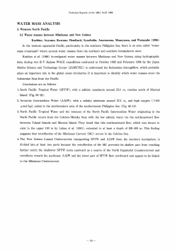
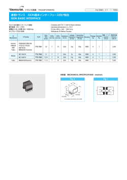
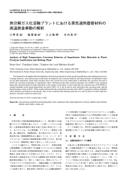
US 20140232845A1
(19) United States
(12) Patent Application Publication (10) Pub. No.: US 2014/0232845 A1
Staker et al.
(54)
Aug. 21, 2014
(43) Pub. Date:
METHOD AND SYSTEM FOR IMAGING
HIGH DENSITY BIOCHEMICAL ARRAYS
WITH SUB-PIXEL ALIGNMENT
20, 2012, now Pat. No. 8,428,454, which is a continu
ation of application No. 12/912,641, ?led on Oct. 26,
2010, now Pat. No. 8,175,452.
(71) Applicant: Complete Genomics, Inc., Mountain
Publication Classi?cation
View, CA (US)
(51)
Int. Cl.
(52)
U.S. Cl.
(72) Inventors: Bryan P. Staker, San Ramon, CA (US);
G023 21/36
Craig E. Uhrich, Redwood City, CA
(Us)
(2006.01)
CPC .................................. .. G023 21/361 (2013.01)
USPC
.......................................................... ..
348/79
(73) Assignee: Complete Genomics, Inc., Mountain
(57)
View, CA (US)
(21) Appl. No.: 14/184,473
(22)
Filed:
biochemical arrays comprises one or more imaging channels
that share a common objective lens and a corresponding one
Feb. 19, 2014
or more time delay integration-type imaging cameras with
optical alignment mechanisms that permit independent inter
Related U.S. Application Data
(63)
ABSTRACT
A method and associated system for imaging high density
channel and intra-channel adjustment of each of four degrees:
X, Y, rotation and scale. The imaging channels are con?gured
to independently examine different spectra of the image of the
Continuation of application No. 13/856,369, ?led on
Apr. 3, 2013, now Pat. No. 8,660,421, which is a con
tinuation of application No. 13/451,678, ?led on Apr.
biochemical arrays.
.-/ 106
(I ‘3‘
e ROTATiON
/,102
x // 104
To; CAMERA
® /'105
l_\.
\> 139
FOUR—DEGREES-OF-FREEUOM
EMAGENG CHANNEL
x OFFSET Cw~/'119
f <3
j ,/115
SCALE
“‘52 <>
,/117
I
5
127\\;._..,
;
;
i :
BEAM SPLiTTER
AND FILTERS
s
'
’
i
i
AUTOFQCUS
AND ILLUWEINATEON
/’125
W?l??
OBJECTWE
/130
LENS
mm
suo
145
,
SECOND CHANNEL
~~~~~~~~~~~~~~~~~~~~~~~~~~ ~-/140
BSTAGE
Patent Application Publication
Aug. 21, 2014 Sheet 3 0f 10
US 2014/0232845 A1
9 RQTATiON
AND XUY STAGE
TDE CAMERA
\ FOUR-DEGREES—OF-FREEDOM
/ iMAGING CHANNEL
U; <1>/ 117 _
SECOND CHANNEL
; ~~~~~~~~~~~~~~~~~~~~~~~~~~ ~7/1a0
127‘\r"“/ 5
BEAMSPUTTER
AND FiLYERS
i
; (/1 i
1/
;
i
L»
s WWWWWWWWWWWWWWWWWWWWWWWWWW _;
AUTOFOCUS
AND stmsNATzoN
//125
OBiECTiVE
ww'l??
/13O
LENS
mm
x, Y STAGE
Fig. 1C
;
145
‘\
137
Patent Application Publication
Aug. 21, 2014 Sheet 4 0f 10
US 2014/0232845 A1
FGUR-DEGREES—OF-FREEDQM iMAGiNG CHANNEL
i
BEAMSPUTTER
ANDHLTERS
‘
l
,4 i
; ,/’§ i
L/
i
l:
;/142
i 3
.........d
3
,
s
l
BEAMSPUTTER E
ANDHLTERS
if
i
E
J
..._....,...‘
',................
“
w
n
u
w
u
w
u
5,441
@
.........,,.........
W
N
u
w
".1
I
127\_M_m8 ;
|
;
/
BEAMSPUTTER ; l/i ;
ANDHLTERS
L/
E
i i
i
i w
m
a
m
AUTOFOCUS
AND ELLUMiNATiON
//125
ww~106
QBiECTiVE
/130
LENS
X, Y STAGE
Fig. 1D
137
_
w
m
n
m
n
u
m
_
w
m
a
m
_
w
m
3/440
3
3
a
m
_
w
a
n
an.
Patent Application Publication
Aug. 21, 2014 Sheet 5 0f 10
X OFFSET DETAiL
Fig. 2
US 2014/0232845 A1
Patent Application Publication
Aug. 21, 2014 Sheet 6 0f 10
US 2014/0232845 A1
210
n/
z
X OFFSET
@ ~
:
6AM)
\205
Y OFFSET
TD! PULSE TEMENG
Hg. 3
Patent Application Publication
Aug. 21, 2014 Sheet 7 0f 10
US 2014/0232845 A1
315
/
Hg. 4
AX
305
Patent Application Publication
Aug. 21, 2014 Sheet 8 0f 10
41.9
415 ”"
‘
Ar
Fig. 5
EMAGE
US 2014/0232845 A1
Patent Application Publication
Aug. 21, 2014 Sheet 9 0f 10
‘
US 2014/0232845 A1
f SCAMERAMSUDE
Y
\j
529
505 \
p
g‘ @suna ~STAGE
I
2225
A
X
Fig‘ 7
\
1:
510
i
/’
1‘
1
526
E
505 \x
/
2
A
E
l
fzs
BMAGE ALEGNMENT
SUDE
\\. sung ALIGNMENT
B
Fig. 8
Patent Application Publication
Fig. 9
Aug. 21, 2014 Sheet 10 0f 10
US 2014/0232845 A1
Aug. 21,2014
US 2014/0232845 A1
METHOD AND SYSTEM FOR IMAGING
HIGH DENSITY BIOCHEMICAL ARRAYS
WITH SUB-PIXEL ALIGNMENT
[0009]
FIG. 1B is a diagram of a second multichannel bio
chemical array imaging system.
[0010]
FIG. 1C is a diagram of a third multichannel bio
chemical array imaging system.
CROSS-REFERENCES TO RELATED
APPLICATIONS
[0001] The present application is a continuation of US.
application Ser. No. 13/856,369, ?led on Apr. 3, 2013, titled
“Method and System for Imaging High Density Biochemical
Arrays with Sub-Pixel Alignment,” which is a continuation of
US. application Ser. No. 13/451,678, ?led on Apr. 20, 2012,
titled “Method and System for Imaging High Density Bio
chemical Arrays with Sub-Pixel Alignment,” now US. Pat.
No. 8,428,454, which is a continuation of US. application
Ser. No. 12/912,641, ?led on Oct. 26, 2010, titled “Method
[0011]
FIG. 1D is a diagram of a fourth multichannel bio
chemical array imaging system.
[0012]
[0013]
[0014]
[0015]
FIG.
FIG.
FIG.
FIG.
2 is a diagram of lateral offset plate.
3 illustrates X andY offsets.
4 illustrates X andY alignment errors.
5 is a conceptual diagram of imaging a spot
with a pixel array using time delay integration.
[0016]
FIG. 6 is a conceptual diagram of results of the time
delay integration imaging of FIG. 5.
[0017] FIG. 7 shows rotational alignment relationships
between two cameras, a slide and a positioning stage before
and System for Imaging High Density Biochemical Arrays
alignment.
with Sub-Pixel Alignment,” now US. Pat. No. 8,175,452, the
contents of which are incorporated herein by reference in
between two cameras, a slide and a positioning stage after
their entirety.
NOT APPLICABLE
REFERENCE TO A “SEQUENCE LISTING,” A
TABLE, OR A COMPUTER PROGRAM LISTING
APPENDIX SUBMITTED ON A COMPACT DISK
[0003]
NOT APPLICABLE
BACKGROUND OF THE INVENTION
[0004]
The disclosure is generally related to the ?eld of
FIG. 8 shows rotational alignment relationships
alignment.
[0019]
STATEMENT AS TO RIGHTS TO INVENTIONS
MADE UNDER FEDERALLY SPONSORED
RESEARCH OR DEVELOPMENT
[0002]
[0018]
FIG. 9 illustrates reference frames used in slide
alignment.
DETAILED DESCRIPTION
[0020] Human genome studies and other uses of biochemi
cal arrays require advanced imaging systems to achieve com
mercially viable data acquisition rates. The number of bio
chemical experiments from which data may be collected per
unit time depends on array density and image acquisition
speed among other factors. Increased array density compli
cates the image acquisition problem because it makes keep
ing track of the identity of each experiment (out of millions)
in an image challenging.
[0021]
For DNA arrays the desired data are usually quater
imaging systems for high-density biochemical arrays.
[0005] High-density biochemical arrays and associated
nary; a nucleotide may be A, C, G or T. These possibilities are
labeled with a set of four different colored ?uorescent
machines allow multiple biochemical experiments, some
times billions, to be performed inparallel. This ability accrues
wavelength and emits light of a longer wavelength. A multi
molecular tags. Each ?uorescent tag absorbs light of a certain
from the development of techniques to perform each experi
channel imager collects data in as many of the four possible
ment in a very small volume and to pack the experiments very
wavelength bins as possible simultaneously.
close together. To observe the experiments ef?ciently,
[0022]
advances analogous to miniaturization advances in other high
technology industries are needed. Speci?cally, what is
needed are fast, accurate, repeatable and robust imaging tech
niques for biochemical arrays.
chemical array imaging systems. Each imaging channel in
these multichannel systems has its own independent adjust
ments for image rotation, x and y offset, and scale (magni?
SUMMARY
[0006] According to the invention, a system and associated
method for imaging high density biochemical arrays com
prises one or more imaging channels that share a common
objective lens and a corresponding one or more time delay
integration-type imaging cameras with optical alignment
mechanisms that permit independent inter-channel and intra
channel adjustment of each of four degrees of freedom: X, Y,
rotation and scale. The imaging channels are con?gured to
independently examine different wavelengths in the image of
the biochemical arrays.
[0007] The invention will be better understood by reference
to the following detailed description in connection with the
accompanying drawings.
BRIEF DESCRIPTION OF THE DRAWINGS
[0008]
FIG. 1A is a diagram of a ?rst multichannel bio
chemical array imaging system.
FIGS. 1A-1D are diagrams of multichannel bio
cation), as hereinafter explained as intrachannel and inter
channel adjustment independence. FIG. 1A illustrates a two
channel system. FIGS. 1B and 1C illustrate the system of
FIG. 1A with alternate means of adjusting x and y image
offset. FIG. 1D illustrates how multiple four-degrees-of-free
dom imaging channels may be added to a multichannel sys
tem.
[0023] The system of FIG. 1A has two simultaneous imag
ing channels each with four degrees of freedom for image
adjustments: rotation, x and y offset, and scale or magni?ca
tion. A high precision positioning stage scans a slide under a
microscope objective lens that is characterized by an axis of
rotational symmetry.
[0024] In FIG. 1A, conventional time delay integration
(TDI) camera 105 is mounted on rotation stage 102. Camera
105 may operate in TDI mode or full frame mode depending
on what operations the system is performing. Lateral offset
plate 110 shifts the position of an image in camera 105. Tube
lens 117 and helper lens 115 together form a zoom lens
system for focusing and changing the size of an image in
camera 105. The rotation stage 102 is con?gured to rotate the
Aug. 21,2014
US 2014/0232845 A1
TDI camera 105 around a common axis of rotational symme
degrees-of-freedom imaging channel independence. In FIG.
try 106 to orient the internal CCD array (not shown) of the
1D beam splitter/?lter assemblies 128 and 129 direct differ
ent wavelengths of light to imaging channels 141 and 142
TDI camera 105 with respect to a sample 145 so that that the
sample 145 can be properly scanned along a scanning axis
104 (through the plane of the ?gure). The camera 105, the
rotation stage 102, the plate 110 and the zoom lens system
formed of tube lens 117 and helper lens 115 together form one
independent imaging channel 139. A second independent
imaging channel 140 comprises a second camera mounted on
a rotation stage, an offset plate and a zoom lens system. Beam
splitter and ?lter assembly 127 directs different wavelengths
respectively. Each imaging channel may contain independent
adjustments for image rotation, x and y offset, and scale or
magni?cation. X and y offset control may be achieved with
tilting plates (e.g. plate 110), mirrors (e.g. mirror 111), time
delay integration pulse timing (as described below) or a com
bination of techniques. The lateral offset plate is described in
more detail in connection with FIG. 2.
[0030] FIG. 2 is a diagram of lateral offset plate 110. Plate
110 shifts the position of images in camera 105. In FIG. 2
of light to the different imaging channels 139, 140. Only one
beam splitter/?lter assembly 127 is shown in FIG. 1A. How
ever, in other embodiments of the system, additional beam
light beam 150 is shown passing through plate 110 and
splitters and/ or ?lters may be moved in and out of the machine
through the plate at non-normal incidence, its position is
system by mechanical robots. Autofocus and illumination
offset by an amount Ax given by:
emerging as light beam 152. Because the beam passes
systems are represented by block 125. Microscope objective
130 common to all imaging channels is focused on a sample
145 in the form of a biochemical array slide that is mounted
I
cosOsinO
Ax = tsinG — —
on a positioning stage comprising rotation stage 135 and X-Y
stage 137.
n
1
2
l — [— sinO]
n
[0025] Light emitted by ?uorescently tagged biomolecules
is collected by the microscope objective and focused onto
pixels in one or the other of the TDI cameras, depending on
where t is the thickness of the plate, n is its index of refraction
wavelength. A system with two imaging channels can record
and 6 is the angle of incidence. A typical glass (n~l.5) plate
image data in two wavelength bins simultaneously. Substitu
that is approximately 2.5 cm in diameter and 3.5 mm thick
weighs only a few grams and may be mounted on a galvo
tion of different dichroic or polychroic beam splitters and/or
?lters 127 allows image data to be collected in additional
wavelength “bins.” Each imaging channel has its own zoom
lens system to adjust image focus and magni?cation. Such
adjustments are typically made when changing dichroic ?l
ters, for example. Each camera may be independently rotated
and the array slide may also be rotated on top of its X-Y
rotation mechanism for quick and precise movements. A ?ve
degree tilt produces an offset of about 100 pm.
[0031] Images may be shifted in the perpendicular (i.e. Y)
direction relative to the X axis through the use of time delay
integration (TDI) pulse timing in camera 105. FIG. 3 illus
positioning system.
trates X andY offsets. Spot 205 is a spot of light imaged on an
array of pixels 210. Arrows indicate how the spot may be
[0026] The zoom system is atypical in that it provides a
constrained and very limited range of magni?cation (scale)
adjustment, but does so with very high precision and stability.
moved with respect to the pixel array. As described above, X
offsets are adjusted by a galvo and offset plate system, while
Lenses 115 and 117 are mounted on precision stages (not
shown) that move them along the lens axes in one micron
steps. In an example system the focal lengths fl and f2 are
about 500 mm and 165 mm, respectively with the maximum
change in scale not exceeding 3%. This precise zoom system
allows the magni?cation of a nominally l6>< microscope to be
adjusted in steps as small as approximately 0.00009>< while
Y offsets are adjusted by TDI pulse timing. In time delay
integration, an image is scanned across pixels in a camera at
(nominally) the same rate that image data is read out of the
pixels. Slight changes in the data read-out rate (or scan rate, or
both) in effect shift the position of recorded images along a
?rst axis, while slight changes in the angle of the galvo
maintaining focus.
controlled offset plate around the ?rst axis can shift the posi
tion of recorded images along the axis normal to the ?rst axis.
Thus the combination of TDI cameras having adjustable tim
[0027] FIG. 1B shows a variation ofthe system ofFIG. 1A.
In FIG. 1B mirror 111 replaces offset plate 110 of FIG. 1A.
The mirror provides an alternate means of offsetting an image
ing and galvo-controlled offset plates offers a quick and pre
cise way to introduce independent, two-dimensional, lateral
offsets in images recorded by cameras in the imaging chan
in camera 105. Second imaging channel 140 is not shown in
FIG. 1B for clarity of illustration.
[0028] FIG. 1C shows a variation of the systems of FIGS.
nels of a multichannel imaging system. Furthermore this
method of introducing image offsets does not depend on
moving a slide with respect to an objective lens.
1A and 1B. In FIG. 1C camera 105 is mounted on x-y posi
tioning stage 103 as well as rotation stage 102. Neither an
just described are useful for making small corrections to align
[0032]
The galvo-controlled plate and TDI offset system
offset plate (e.g. 110 of FIG. 1A), nor an offset mirror (e.g.
an image of a biochemical array with an array of pixels in a
111 of FIG. 1B) are included in one of the channels of the
camera. (The control mechanism is beyond the scope of this
disclosure.) FIG. 4 illustrates X and Y alignment errors
system of FIG. 1C. Rather, mechanical x-y positioning stage
103 provides lateral offset control for camera 105.
[0029] FIG. 1D shows how systems like those illustrated in
FIGS. 1A-1C may be constructed with any number of imag
between a spot 305 in an image and an array of pixels 315. In
FIG. 3, dotted circle and plus sign symbol 310 denotes the
ing channels, each with parameters adjustable independently
center of a pixel. The symbol comprising a solid circle and
plus sign 305 indicates the actual position of a spot in an
of one another and each channel being adjustable indepen
image. “Ax” and “Ay” show the difference between positions
dently of any other channel so that adjustments in one channel
have no effect on other channels. This intrachannel and inter
305 and 310. In one particular system, each 8 pm by 8 pm
camera-based pixel images and thus corresponds to a 500 nm
channel adjustment independence is herein denoted as four
by 500 nm area of a biochemical array. It has been found that
Aug. 21,2014
US 2014/0232845 A1
an imaging system such as the one illustrated in FIG. 1 can
[0047]
maintain alignment to a biochemical array with better than 20
nm accuracy while scanning more than one million data spots
per second.
as described in connection with FIG. 9, which illustrates
Alignment of the slide with the X-Y stage proceeds
reference frames used in slide alignment. In FIG. 9, reference
principle X-Y stage 137 in FIG. 1 can move in any direction
in the X-Y plane. Diagonal movement is created by a com
frame 605 is aligned with an X-Y stage such as X-Y stage 137
in FIG. 1. Reference frame 610 is aligned with a slide such as
slide 145 in FIG. 1. The two reference frames may be rotated
with respect to one another by a rotation stage such as rotation
stage 135 in FIG. 1. In order to determine the required rotation
bination of X andY movements. In practice, however, stage
accuracy is best if one dimension (e. g. X) is ?xed while
movements in the other dimensions (e.g. Y) are taking place.
the slide, such as points “a” and “b” in FIG. 9, are measured
in each reference frame. The location (x, y) of a point in the
[0034] Similarly, time delay integration cameras achieve
highest precision when they are scanned parallel to the direc
stage reference frame is known from digital positioning com
mands issued to the stage.
[0033] Achieving high throughput with high density arrays
depends in part on accurate mechanical scanning stages. In
tion of data read-out. FIG. 5 is a conceptual diagram of
imaging a spot with a pixel array using time delay integration.
Misalignment causes image smearing as shown in FIG. 6
which is a conceptual diagram of results of the time delay
integration imaging of FIG. 5.
[0035] Spot 405 is imaged by array of pixels 415. The
relative motion of the spot and the pixel array is shown by the
angle (and offset and scale relationships), several points on
[0048]
The location (x', y') of a point in the slide reference
frame is determined during image alignment procedures. If N
points, indexed by i:l to N are measured in both reference
frames, then for point i one may write:
dotted arrow originating at spot 405. The arrow is not aligned
with the pixel array and smeared image 420 is the unfortunate
result. Spot 410 is also imaged by array of pixels 415, but this
time the relative motion of the spot and the pixel array is
[0049] The expansion above has been carried out up to
second order. Expansions to higher order, or in other coordi
nate systems, etc., may be used without loss of generality.
shown by the dotted arrow originating at spot 410. The arrow
Next, an error term may be constructed:
is aligned with the pixel array and image 425 results.
[0036] Practical limitations of positioning stages and cam
era time delay integration systems highlight the utility of
providing each camera, and the slide X-Y stage, with rotation
stages. FIGS. 7 and 8 show rotational alignment relationships
1
between two cameras, a slide and a positioning stage. If one of
these four elements is considered to be ?xed, three degrees of
rotational freedom are required to align the other three ele
ments.
[0037] In FIGS. 7 and 8, X andY axes 505 represent the
orientation of a stage such as X-Y stage 137 in FIG. 1. The
orientation of cameras in the ?rst (e.g. camera 105 in FIG. 1)
and second imaging channels are represented by 510 and 520
respectively. The orientation of a slide, such as slide 145 in
FIG. 1, is represented by 525. In FIG. 7 the two cameras, the
slide and the stage are all rotationally misaligned with respect
to each other.
[0038] Aligning all of these elements as shown in FIG. 8
may be accomplished in a process that involves aligning the
cameras 510, 520 to the slide 525 and aligning the slide 525 to
the X-Y stage. An example of such a process is:
[0039] A. Take an image of an array of biochemical
experiments on the slide using one of the cameras.
[0040] B. Calculate the angle, SCAMERA_SLIDE, between
the camera and the slide using image alignment proce
dures. Store this angle for later use.
[0041]
C. Find the angle between the slide and the X-Y
stage, GSLIDESTAGE, using slide alignment procedures
described below.
[0042]
D. Rotate the slide by the angle found in step (C)
to align it with the X-Y stage axes.
[0043] E. Rotate the camera by the sum of the angles
found in steps (B) and (C) to align it with the stage.
[0044] F. Repeat the slide alignment procedure of step
(C) to obtain a new slide mapping.
[0045]
G. Repeat steps (B) and (C) to con?rm all angles
equal to zero. If not, repeat entire process.
[0046] H. Repeat the entire process for the other cam
eras.
[0050]
Then, X2 is minimized to ?nd coef?cients am, am,
am, . . . , boo, blo, b0], . . . , etc. Finally the angle between
reference frames may be calculated from the coef?cients.
[0051]
Once cameras, slide and stage are aligned, data
acquisition may begin. The imaging systems of FIGS. 1 have
both static and dynamic image adjustment capability. Static
adjustments include magni?cation via zoom lens systems,
rotation via a set of mechanical rotation stages, and wave
length selection via beam splitter and ?lter choices. Static
adjustments are made before slide scanning operations begin,
while dynamic adjustments can be made during a scanning
operation.
[0052] Dynamic adjustments include small X andY offset
changes made via TDI pulse timing and galvo-driven rotation
of a transparent ?at plate, e. g., 110, rotation of a mirror, e. g.,
111, or translation of a stage, e.g., 103. The dynamic adjust
ments may form part of an image-based control loop that
corrects positioning error during scanning operations. The
control loop involves acquiring images in cameras, clocking
out image data from the cameras, analyzing the data, calcu
lating error corrections and adjusting X andY offsets via TDI
pulse timing and galvo plate angle.
[0053] As one skilled in the art will readily appreciate from
the disclosure of the embodiments herein, processes,
machines, manufacture, means, methods, or steps, presently
existing or later to be developed that perform substantially the
same function or achieve substantially the same result as the
corresponding embodiments described herein may be utilized
according to the present invention. Accordingly, the
appended claims are intended to include within their scope
such processes, machines, manufacture, means, methods, or
steps.
Aug. 21,2014
US 2014/0232845 A1
[0054]
The above description of illustrated embodiments of
While speci?c embodiments of, and examples for, the sys
shift the position of the image in the camera in a plane
normal to the scanning axis.
2. The imaging system of claim 1, Wherein the lateral offset
system comprises a mirror to redirect the axis of rotational
tems and methods are described herein for illustrative pur
symmetry.
the systems and methods is not intended to be exhaustive or to
limit the systems and methods to the precise form disclosed.
poses, various equivalent modi?cations are possible Within
the scope of the systems and methods, as those skilled in the
relevant art Will recognize. The teachings of the systems and
methods provided herein can be applied to other systems and
methods, not only for the systems and methods described
above.
[0055] In the following claims, the terms used shouldnot be
construed to limit the systems and methods to the speci?c
embodiments disclosed in the speci?cation and the claims,
but should be construed to include all systems that operate
under the claims. Accordingly, the invention is not limited by
the disclosure, except as indicated by the claims.
What is claimed is:
1. An imaging system comprising:
a microscope objective;
a camera con?gured to produce an image from scanning of
a sample along a scanning axis normal to an axis of
rotational symmetry of the microscope objective; and
a lateral offset system along the axis of rotational symme
try, the lateral offset system con?gured to independently
3. The imaging system of claim 1, Wherein the sample
comprises a biochemical array that is mounted on an x-y
positioning stage.
4. The imaging system of claim 1 further comprising a
zoom lens system, the zoom lens system being con?gured to
change the scale of the image directed to the camera along the
axis of rotational symmetry.
5. The imaging system of claim 1, Wherein the microscope
objective comprises an objective lens con?gured to direct the
image to the camera along the axis of rotational symmetry.
6. The imaging system of claim 1 further comprising a
positioning stage, the positioning stage being translatable in
an X direction and a Y direction in a plane normal to the axis
of rotational symmetry, Wherein the sample comprises a bio
chemical array mounted on the positioning stage.
7. The imaging system of claim 1, Wherein the camera is a
TDI camera that is con?gured to perform alignment in theY
direction.
© Copyright 2026 ExpyDoc