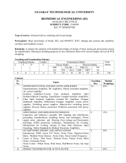
Original Report
An Optimum Linear Receiver for Transmission Systems with
Noise Depending Multiplicatively upon Signals
MikioTAKAHARA
(Received August 31,1978)
Abstract
The considerations of the optimum reception of systems with additive and multiplicatively
dependent noises are very useful. Besides, the analytical results are much desirable to obtain
the conception of behavior of those systems. But it is very di伍cult, even if by numericaI
evaluation, to estimate the optimum reception with high fidelity for those systems.
In this paper, for the above purpose, we assume the simplest model including the multi−
plicatively dependent noise and calculate the impulse response of the optimum filter for the
two different criteria:signal−to・noise ratio(SNR)in a digital system and mean square error
in an anlog one.
For the first criterion, the optimum丘1ters of two cases, that is, systems with and without
intersymbo1・interferences, are considered. In the former systems, the impulse response of
the optimum丘lter is hardly different from the conventional one.
For the second criterion, the optimum丘lters of three cases are discussed:(a)continuous
wave,(b)isolated wave and(c)PAM wave. For the last case, under some restrictions,
the optimum filter can be composed of the cascade connection of a matched丘lter and a
transversal filter.
noise, because of its ease of treatment,
1. INTRODUCTION
Some practical examples containing the multipli・
An input−output relation in any system may be
お の
generally represented, in a sense, by a sort of
problems based on irregularity of Earth surface2),
catlve nolse are shown as follows;the multi・path−
transmission systems, in which signal and, noise
the fading channel problems3), the analysis of
which is undesirable to be transmitted, exist.
automatic gain control4), the structual noise prob・
Moreover, the noise is classified into two groups
lems in the image engineering5), etc. Though the
such as noise independent of signals and noise
noise’generated・processes as shown in these ex−
dependent on them. The former is represented by
amples may be distinguished respectively, the
the thermal noise, while the latter may be supposed
following consideration for the multiplicative noise
various types of dependency on signals. Then to
may give a suggestion or help to solve vari皿s
solve generally the optimization problem of systems
types of noise depending on signals.
containing the noise depending on signals, may be
We have already reported the maximum likelihood
very di伍cult. For example, Dr. Horiuchi
treated
detector6)in the system containing thermal noise,
with this problem using the conception
of the
multiplicative noise and intersymbol interference.
non・linear transduceri).
Then, in this report, the optimum linear receiver,
For the first stage to consider various
types of
of which criterion is signal・to−noise ratio(SNR)
dependency, we treat with noise
depending on
in digital systems or mean・square−error in analog
signals multiplicatively, that is,
multiplicative
systems・is considered in transmission systems
一47一
December 1978
Report of the Faculty of Engineering, Yamanashi University
No.29
containing two types of noises such as noises
where Ml(t)is a zero・mean random variable and
independent of and dependent on signals.
ロ
mo 1S a COnStant.
First of a11, the optimum linear丘lter for an
2. TRANSMISSION SYSTEM MODEL
isolated pulse without intersymbol interference and
Generally speaking, noise depending on signals
then one for pulse・sequence with intersymbol inter・
is shown with a functional F{zo(り}of received
ference are considered.
signal zo(り. The simplest type of this functional
3.1.1 1SOLATED PULSE
may be expressed a product m(t)by zo(t), i. e.,
Signal power at the decision point t=O is
m(り・20(t).Then a consideration for an optimiza・
・i…1・・w・・一
tion problem of reciver of systems containing such
早轣F..(M1(・)
栩・)・・(・)カ()d・]2}t.。
amultiplicative noise may be very available for
considerations of noise generally depending on
signalS.
一・・
The transmission system model is shown in Fig.
o∫:..・・(・)h(一・)d・}2, (・)
Where E。[・]shows ensemble average for x.
1,for which analysis is performed in this report.
Additive and multiplicative noise are, respectively,
3. OPTIMUM UNEAR FILTER IN DIGITAL
additive noise power
−∫:..N・H・(ω)4ω一N・∫ン・(一・)d・・(・)
TRANSMISSION SYSTEMS
In this chapter, singnal’to・noise ratio is adopted
multiplicative noise power
as a criterion in digital systems and the filter
−∫:..∫:..Em・』⑳1(・)]・・(t)・・(・)h(−t)
maximizing the criterion is defined as the optimum
×h(一τ)dtdτ, (5)
linear filter. Then the formulation for this purpose
is performed and impulse responses of the optimum
where H(ω)is the Fourier transform of h(り. If
linear filter are computed under various specific
the fluctiation part of the multiplicative noise is
conditions.
white, we have
3.1 FORMI几ATION
Em、[Ml(t)Ml(τ)]=Moδ(t一τ).
Throughout analysis in this chapter, it is assumed
Substituting Eq,(6)into Eq.(5),
that the received signal zo(t) contains the effects
(6)
E・・(・)−M・∫:..・・2(・)h・(一琉
(7)
of transmission line, the instantanious decision is
t
used and additive noise is white. Then, SNR at
From Eqs.(3),(4)and(7), SNR is
the decision point is defined as
SNR−m・2
SNR=signal power at the decision point/
o∫°°
) ...2・(τ)h(一τ)dτ}
N・∫:..h・(一・)d・+M・∫:..・・2(・)h・(一晒
(additive noise power十power of noise depend−
ing upon signals十intersymbol interference).
(8)
(1)
Then, provided that the linear filter output at t= o,
Under preceding conditions we would determine
that is, y(0) is
the impulse response of the optimum linear丘1ter
・(・)−m・∫:..・・(・)h(一・)d・−A(・・n・t・n・)・
which maximizes Eq.(1).
Throughout this paper the multiplicative term
(9)
〃2(t)is shown as
the maximization of Eq.(8)is equal to the minimiza一
m(t)=m1(t)叫ト〃lo, (2)
x(の 。。(り 。(の
Mi(t), n(t):stationary random processes
TRANSMISSION
LINE
G(f):transfer function of transmission
TRANS−
MITTER
with zero−mean.
G(f)
9(の
m(t) n(t)
Hω
h(t)
=m、(の+m。
一48一
line.
Fig.1 Transmission system mode1
An Optimun Linear Receiver for Transmission Systems
tion of the denominator of Eq.(8). Adding Eq.(9)
as a condition to the functiona1, consequently the
o∫:..・・(・)h←・)d・}2
θ・・m・2
SNR=
new functional l is
(16)
∫。[h(一τ)]
where
・−N・∫ン・(一・)d・+M・∫:..・・2(・)h・(一・)d・
・・[h(一・)コーN・∫:..h・(一・)d・櫛・2顯E[θ・θ・]
+z
om・∫:..・・(・)h(一・)d・−A} (1・)
・∫:..∫:..・・(・−iT)・・(t一ノT)h(一・)h(一りd・dt
whereλis Lagrange multiplier.
+再[・1θ・]∫1..∫:..E[m・(t)Ml(・)]・・(・一の
Applying calculus of variation to Eq.⑩, the
impulse response of the optimum linear filter is
h・@)一
×z。(オー元7’)h(一τ)h(−t)dτdt
ッ当識。(λ・一一λ)・al)
Using the same procedure used for Eq.(10), the
functional of Eq.㈹is
If Mo=O in Eq.(iO, the optimum impulse response
・一・・[h(一・)]+m・θ・λ{∫:..・・(・)h(一・)d・−A}・(・カ
is
h・(り一λ゜m°
ノ一り ⑫
If we write h(t)as ho(t), the minimization of Eq.
⑰is
which is in accord with the response of the con−
」Voho(一τ)十mo2ΣΣE[θ‘θゴ]Zo(τ一iT)
ventional rnatched filter.
i2EOJキ0
・∫:..・・○τ)h・←t)dt+翠写[θ馴・一の
While, If、No=O in Eq. ai), the optimum impulse
response ls
・∫:..E吻⑳・(・)]・・(t−∬)h・(−t)dt
h・(り一M。禁汀(・・←t)キ・) ⑬
which is in propotion to the inverse of the time・
+λ、〃2。θ。z。(τ)=O as)
whereλ1=λ/2.
reVerSal・signal.
Though to solve generally Eq.国 for ho(り is
3.1.2PULSE SEQUENCE WITH INTER−
difficult, we can solve it by assuming the whiteness
SYMBOL INTERFERENCE
In this chapter, we express a binary symbol
of multiplicative‘noise(cf. Eq.(6))as follows;
ho(り
sequence as{θτ}(θt=Oor 1, with equal probability)
and a i・th received signal asθτzo(t−iT). There
一一
香Eθ・Z・Z・←t)−m・誓恩。E[θ1θ・]Z・(+のy・
2V。+Q(一り
are two distinctions from the preceding case, one
(19)
of which is that the system has the third noise
component of intersymbol interference and the other
is to have to rewrite a multiplicative noise term
then
,、−m。「°°
z。(t−IT)h。(−t)dt
°°
@Moλ1θoZO(τ)20(τ一IT)
dτ
intersymbol interference
−・2
⑳
J−co
as follows.
・・一一
.。. 」v。+Q(τ)
福d[θ1θ・コ/f..∫:..・・(・一の
..〃2・Z。(τ一1T)ΣE[θ、θプ]2。(τ一の
∫
一婆。・・... 景Q(。) d・
×z。(‥ゴT)h(一τ)h(−t)dτdt ⑭
㈱
multiplicative noise power
Q(り=MoΣΣE[Otθ」]ZO(’−iT)ZO(t一ノT)
一習E[θ・θ・コ∫:..∫:..E[Ml(・)Ml(り]
i フ
(−m≦ゴ,ノ,19n) 幽
×z。(t−iT)z。(τ一刀’)h(一τ)h(−t)dτdt ㈹
where m,〃are a number of time slots due to
Where T is a pulse interva1。 Therefore noise is
intersymbol interferences of zo(t)and ho(り. We
donoted by sum of three components of additive
can obtain the required impulse response ho(りfrom
noise, multiplicative noise and intersymbol inter・
Eqs.(19),¢◎and¢]).
ference such as Eqs.(4),(11i and(15), respectively,
3.2 CALCULATEI)RESUI.TS
the SNR is
To consider the effects of multiplicative noise for
一49一
December 1978
Report of the Faculty of Engineering, Yamanashi University
1.0
べ 刀
No.29
A(2)
敵((・)
i1)
(2)
古
一2.0
0
一1.
霊疏さ
z;IL;
2.0
@ ク
t/T
一〇.4
0.4
(1) Input SNR==18.4dB
t/T
(2)Input SNR=17.6dB
Input mu1/add=36.8dB
Input mu1/add=3.2dB
Fig.2
.1.0
Impulse response of optimum filter in
Input mul/1.1.・=−14.1dB
Input mu1/1.1、=−4.1dB
systems without intersymbol・interference
Output SNR=28.3dB
Output SNR=23.9dB
Fig・5 1mpulse response of optimum filter
(1) Input mul/add=−7.9dB (2)
Ihput mul/add=・−O.9dB
Input SNR=・19.2dB
Input SNR= ・17.2dB
Output SNR=26.8dB
Output SNR=25.5dB
Output mul/add =−9.5dB
Output mul/add=−3.OdB
ln systems with intersymbol
interference
1.0
(3)
Input SNR=10.2dB
Output SNR=20.ldB
1.0
NtXx
0.5
Input mul/add=9.ldB
Output mul/add=4.2dB
藻
i 、、 1
10
0.5
一9、
、 、
、、
20
{
</(2)
一 一 一
60
50
40
30
10
f(1/T)
f(1/T)
Fig.3 Spectrum of impulse response of Fig.2
Fig.6
Spectrum of impulse re・
sponse of Fig.5
1.0
1.0
、(3)
’
7
/ノ
input waveform
\
一3.0
・2.0
一2.0
3.0
\.
0
\
一1.0
一〇.4
一〇.2
O
0.2
0.4
1.0
t/T
t/T
Fig.7 0utput waveform of optimum filter
Fig.4 0utput waveform of optimum丘lter
signals, characteristics of ho(t), Ho(f) and y(t)
From above results, it is known that the optimum
are computed for the various ratios among three
linear丘lter’s impu1§e response of systems with
noise components, i. e.,additive noise, multiplicative
dominant additive noise and without intersymbol
noise and intersymbol interference. Then zo(りis
interference has a kind of dent at the top of
assumed to be the gaussian waveform.
response. The results may be qualitatively explained
Now characteristics of ho(t), Ho(f) and y(t)
as follow. Since the noise component increases at
with parameters of the ratio of multiplicative noise
an instant of the large amplitude of signals, a
power to additive noise power, are shown in Figs.
filter intendes to relieve signals from the effects
2∼4,where intersymbol interference can be neg・
lected, and shown in Figs.5∼7, where intersymbol
interference can not be neglected.
of noise. When intersymbol interference and addi・
ウ コ
tlve nolse are negligibly small, the impulse response
of the optimum五1ter rises up abruptly at t=T
一50一
An、 Opt.imum Linear Receiver for Transmission Systems
(consequently the response dents at the neigh−
Then as the linearity and the time invariancy of
bourhood of t=0). Consequently the transfer
systems are assumed,
function occupies considerably wide band. Then
〃、、(s,σ)=〃、、(s一σ), ¢カ
according as additive noise increases, band width
h。(ちσ)=h。(t一σ), 2s)
can not help becoming nallower to obtain good SNR.
le、w(s,り=㌦(s一り ⑳
Therefore, the impulse response approaches asymp・
are obtained. Moreover if t=O in Eq.26), we obtain
totecally the gaussian waveform according as a
∫:..le・z( ・)h・(・)d・−kwz(・) e◎
parameter of mul/add decreases.
While for the signal with intersymbol interference
such as a sampling function type, we obtain an
analogous result of the conventional response
instead of Eq。㈱. By means of the Fourier trans−
form of Eq.㈹, we obtain
H。(∫)=1(w、(∫)/1(、、(∫). 勧
Hereatfter, a function expressed with the capital
waveform.
letter shows a frequency domain function and a
4. OPTIMUM LINEAR FILTER FOR ANALOG
small−1etter・function a time domain function.
TRANSMISSION SYSTEMS
Now, three cases as speci丘c examples are dis−
In this chaper, the mean・square・error is chosen
cussed as follows;(a)acontinuous signa1,(b)an
as a criterion for optimization and a filter minimizes
isorated pulse,(c)aseries of PAM signals.
this criterion is defined as the optimum linear filter
4.1 0PTI]MIZATION FOR CONTINUOUS
for this analog transmission system.
SIGNAL
Criterion l is
As a transmitted signal x(の1s continuous, the
1=E[ly(り一w(り12] 23)
considering system is stationary. Therefore, w(t)
where y(t)is a filter output and w(りis the refer・
and z(t) are respectively
ence signaL Then we want to decide h(t, s)which
ω(り=x(り, 岡
・(’)一願)∫:..・(・一・)・(・)d・+・(り倒
minimizes 1. Here, s is a variable of time due to
without time−invariant condition. Using
・(り一
全{〃2、(t)+m。}20(り+n(り
轤P..h(ち・)・(・)4・
(in
where勿(りand n(りare illustrated’in Fig.1
feach・.noise is not assumed), a
which whiteness o
Eq.㈱becomes
transmission line is time invariant and its impulse
轣F..∫:..〃・・(・,・)h(ち・)h(ち・)d・∂・
∫一
response is expressed as g(t).
−2∫1..h(魂・(s・・t)∂・+〃一(ちり 24
Auto−and cross correlation functions of z(t)and
x(り are, respectively
where z(t)is a filter input and lexa(sの, kzw(s,t)
are defined as
㌧(s一り=㌦(s一りk。。。。(s一り+lenn(s一り,(34
1e。。。(S−t)=〃Z。カ。。。(∫−t) 陶
〃、、(s,t)=E[z(s)2(り],
Substituting the Fourier transforms of Eqs. B4 and
ゐ、ω(s,’)=E[2(s)w(’)]. ⑳
βS)into Eq. BO
They are auto−and cross correlation functions of
processes z(のandω(り. Hereafter above expres−
sions of subscripts are used to denote correlation
1(、、(∫)=K㌦m(ゾ)⑧瓦。。。(∫)+1(。。(∫), ㈹
K。。。(∫)=Kxx(f)G*(∫). βカ
Then the optimum linear filter transfer function
functions.
Ho(ア)is shown as
Substituting auto−and cross correlation functions
H。(f)
into Eq.幽and applying calculus of variations for
〃201(xx(∫)G*(f)
the results, the impulse response of the optimum
linear filter is obtained by solving
∫1..〃・(s,σ)hσ(ちσ)4…〃・・(…)・ 2・)
陶
K_、(∫)⑧・K。。。。(f)+m。2K。。。。(∫)
+1(nn(∫)
where⑧and * denote convolution integral and
complex conjugate, respectively, and K。。。。(f)
一51一
December 1978
Report of the Faculty of Engineering, Yamana鱒上University
No.29
=Kxx(f)IG(∫)[2.
w(t) and z(の are
Eq.倒is in accord with the response of the con・
w(t)=aδ(t), z(t)=am(t)9(t)十n(t) (49
ventional Wiener filter when multiplicative noise
respectively. Consequently, auto・and cross correla−
is neglected. As this noise operates multiplicatively
tion functions are
on signals, signal and noise are denoted by the
leaa(s,σ)=a29(s)9(σ)lemmp(s一σ)+〃。。(s,σ),
㈹
convolution integral.
k、w(S,t。)=a2m。9(S)δ(t。)
㊨
If Km、m、(ア)=Mo(assumption of whiteness of
respectively. Substituting Eqs.96),㈲into@1)
multiplicative term),
∫:..{Zi・’・lg(・)・(・)le−(・一・)+lenn(・一・)}
Km、m、(∫)⑧1(。。。。(∫)
×h。(t。一σ)dσ=α2〃2。9(S)δ(t。)・
−M・∫:..K・・x・(ゾ炸C・(・・n・・…)・
倒
assuming the whiteness of additive and
1・恥㈲・
Then Eq. BS)reduces to
multiplicative noises same as the foregoing chapter,
_ 〃2。Kxx(∫)G*(ア)
the impulse response of the optimum linear filter is
㈹
H。(f)
m。2K。。。。(∫)+C。+Knn(f)’
h・(り一嘉袈竺1識。 ㈲
When the且uctuation of multiplicative noise is
very slowly in comparison with that of signals,
where
the spectrum band width of a received signal is
C・−1−m・∫:..・(・)h・(一・)d・・
much wider than that of multiplicative noise.
Therefore Kxx(∫)is constant in comparison with
The above result is in accord with Eq. a])except
1(m、7π1(∫). Consequently
aCOnStant nUmber.
1(殉殉(∫)⑧1(。。。。(∫)=t・a.、2・K。。。。(!)
4.3 0PTIMIZATION FOR PAM SEQUENCE
Then the transfer f皿ction of the optimum linear
In this chapter we deal with PAM sequence as
an contact point of analog and digital transmision
filter is
systems. Since this system is denoted by a periodic
m。・臨。(f)G*(ゾ)
㈹
H。(ゾ)at
(σm、2+m。2)K。。。。(∫)+K。。(ゾ)
stationary process, Eq.㈱is written as
where
∫°° 6・)
・・、2−「:..Km、・1(∫)4ゾ・
pulse一
where i is an arbitrary integer and T is a
v
4.2 0PTIMIZATION FOR SINGLE PULSE
period. The Fourier transform of Eq.輌is
Now we consider the impulse response or transfer
∫:..H・*(・)・x・(一ノ2・・iT)Bz2(f・ y)d・
function of the optimum linear filter for an isolated
pulse over transmission line. We decide Eq.⑳as
a starting Point of this analysis since a non・
stationary system is delt in this chapter. Provided
=C、w(f, iT)
61)
where
C,w(ゾ, iT)
合「°°le、w(・,の・x・(一元2π∫・)ds.
t=ちin Eq.佗6), its Fourier transform is
62)
レー◎◎
∫:..k・・(・,・)h・σ一)d・−le・・(・・t・)・ ⑪
PAM sequence at the receiver input is
x(t)=Σ靱(t−kT)
∫:..H・*(・)・xp(一ノ2・…)B・・(∫・・)d・−C・・(〃・)
63)
虎
where
②
E[ale]=δ.
where
E[akak+m]=α況=α_m for all〃,
Bzz(f,レ)
㌶1㌫∴(り.}
全∫:..∫:le・・(…)・x・[一元2・(ゾ・一・・)]d・d・蜘
64
Ca・(〃・)全∫:..le・・(・・t・)・xp(−」2・ゾ・)⊇
Auto・and cross correlation functions of
Since a transmitting signal x(り is x(t)=αδ(り,
w(t)are
一52一
z(りand
An Optimum Linear Receiver for Transmission Systems
le、、(s,σ)Σα↓Σσ(s−leT)9(σ一
t k
(le+1)T)lemm(s一σ)+le。n(s一σ), 6S)
編(s, iT)ニ〃z。Σ ev、..、9(s−kT). 66)
k
Using the Poisson sum formula, Bzz(ゾ,レ)is
B、z(f,レ)
一翠δ( 1レーf−’6’)∫:。K−(ゾーξ)G(ξ)G・(∫÷・)
which Knn(f)and Km、m1(f)⑧{[G(f)12Z)(f)} are
additive and multiplicative noise spectrum densities,
respectively. Consequently we know that the
optimum linear filter transfer function can be
expressed with only power spectral densities of
signal and noises same as the conventional case.
The multiplicative noise term in Eq.㈹contains
aconvolution integra1, then we reunderstand the
×L)(f一ξ一レ)dξ十δ(f一μ)Knn(∫). 67)
multiplicative effect between signal and noise, and
The other hand, Caw(f, iT)is
the signal dependency of noise in this transmission
Czw(∫, iT)=moTG(f)D(f)exp(一ノ2πiTf)6S)
where
T」り(ア)=Σ d、exp(一プ2π2Tプ). 69)
i
Substituting Eqs.67),6S)into Eq.6])
system.
[Example 2]
Here we assume that noise is white in return
for a looser Nyquist condition than Example 1, i. e.,
¥H・*(ゾー⊥)∫:..K−(f一ξ)G(ξ)G・(ξ一
1(。,、(f)=ノV。,1(叩、(∫)=M。
∫:..{G(ノ)㎡D(∫)}・IG(ゾー÷)v/D(f−f)}df
÷)D(ξ)dξ一[一・H・*(f)Knn(f)一・TG(ゾ)D(∫)・
=0 (片0)
㈹
陶
If the difference equation of Eq.(60)can be solved
generally, the optimum linear 丘lter transfer
function of this system is obtained. Unfortunately,
we can not generally solve this equation except
examples restricted with some conditions、 Two
specific examples of solutions of Eq.㈹restricted
Two integrands in the above equation denote to
be orthognal each other at 1=0. A solution of
this equation is obtained heauristically as
H。(ア)
m。TG*(f)D(ゾ)
閾
N・+m・2D(f)翠G(f−÷)2 ’
with some conditions are shown following.
[Example 1]
The transmission line is assumed to be limitted
パco
+M。 D(∫)|G(f)12∂∫
ゾ ーe◎
We can ccmposite both transfer functions of Eqs.
by the Nyquist band, that is,
G(f)≡o,1ゾ1>1/2T 圃
Substituting Eq.圓into Ep.6S), we get
Ho(f)
㈹and㈹with a cascade conection of a matched
filter and a transversa1丘lter. As an example, one
configuration of Eq.㈹is shown in Fig.8.
m。TG*(ゾ)D(ゾ)
聞
Knn(∫)+Kmm(f)(釧G(∫)i2D(f)}°
By means of rewriting Kmm(f), the required
transfer function is
・・卿/〔・8・岬・σ一丁)1・冊M・.ゆσ)
×IG(∫)12明△ΣC。ei27「VfT
z(t)
H。(f)
m。TG*(f)D(f)
㈹
K。n(∫)+m。21G(∫)121)(∫) ’
+1(剛、(ゾ)(釧G(∫)12D(ゾ)}
y(t)
When the system contains additive noise only, Eq.
Σ 〉一一→
綱is
sampling at
t=IT
H・(f)−K。。;C瑠1{;(f) (・4
(1・・;・O,±1,±2,…)
which is in accord with the conventional result8).
In Eq.⑭, if we rewrite Knn(∫)with Knn(f)
十Km、m、(∫)⑧{IG(f)12Z)(∫)}we obtain Ep.倒, in
−53一
T
C−h
Fig.8 Structure of optimum filter on Eq.66
December 1978
Report of the Faculty of Engineering, Yamanashi University
No.29
1ate Dr. Pro Kosaku Aikawa of Yamanashi U.,
5. SU]MMARY
Dr. Pro. Shigeo Tsujii, Mr. Takashi Yamamoto,
The impulse responses or transfer functions of
Mr. Susumu Nakamori of Tokyo Institute of
the optimum linear filter are obtained for criteria
Technology, Dr. Kazuo Kamata of Utsunomiya
of SNR in digital transmission systems or of mean・
U.,and Dr. Pro. Kazuo Horiuchi of Waseda U.,
SqUare errOr in analOg tranSmiSSiOn SyStemS.
who was so kind as toexplain me for his papers.
Consequently, we known, in digital transmission
REFERE]NCES
systems, the optimum linear filter impulse response
is a particular shape with dent at the top of a
1)
Investigation of inforrnation and control,2, P.
responses of systems are computed for various
ratios among additive, multiplicative noise and
K.Horiuchi and M. Amano;“Generalized丘1ters
for rejection of nonlinearly coupled noises”,
waveform, and we explain it qualitatively. Some
23 (1964.02).
2)
Painter and Gupta;“Recursive ideal observer
intersymbol interference.
detecti°n°f kn°wn M’a「y signaals i・m・1>ipli’
In analog communication systems, the transfer
梛 簿
functions of the optimum Iinear filter are shown,
cative and additive gaussian noise”,IEEE Trans.
Com. COM・218, P.94(Aug.1973).
3)
Prassad and Mahalanabis;“On the estimation
and their characteristics are computed for some
of gaussian signals in multiplicative channels”
practical or particular examples.
Arch. Elektron&Ubertraguns. tech.,28,9, P.
387 (Sept.1974).
Apart from the question of whether an analysis
4)
developed in this paper can be apPlied for the
linea「ity to automatic gain control”, IEEE
general system containing noise depending on signals
or not, this analysis may be available to understand
Stochham;“The application of generalized
Trans. AU−1阜2, p.267(June 1968).
5)
Lohmann;“Image formation and multiplicative
noise”, J. Opt. Soc. Am,55,8, P.1030(Aug.
for a f皿damental tendency of the optimum linear
1965).
system with such noises.
6)
S.Tsujii, M. Takahara and T. Yamamoto;
Hereafter problems for some practical systems
“Optimum receiver for digital signal with
and for the realization of filter should be discussed.
multiplicative noise, additive noise and inter−
symbol interference”IECE Tranc Tras.,59・A,
Shot noise in optical communication systems, pro’
blems of which may be distinguished from those
9,p.756(Sep.1976).
7)
S.Tsujii, M. Takahara and K. Kamata;“On
of this paper, is one of noises depending on signalsg).
waveform equalization and its economical profit
Therefore these results in this paper may be
in optical丘ber PCM transmission systems”,
IECE Trans.,58西A,11, P.683(Nov.1975).
applied for a certain problem in those systems.
8)
L.E. Franks;“Signal theory”, Prentice・Hall
9)
T.Taki, M. hadori and Y, Arakawa;“The
We hope to be available these results for more.
general systems containing noise depending on
signals such as the fading channels, the image
(1969).
noise equivalent circuit of the optical com−
munication receiver system and the optimum
tranSmlSS10n SO On.
design of the linear receiver”. CS 76−156, IECE
of Japan(dec.1976).
ACKNOWLEDGEMENT
The auther wish to express his thanks to the
一54一
© Copyright 2026 ExpyDoc