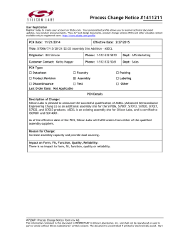
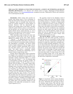
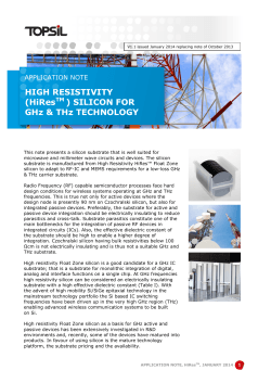
International Journal of Innovation and Applied Studies
ISSN 2028-9324 Vol. 8 No. 1 Sep. 2014, pp. 107-113
© 2014 Innovative Space of Scientific Research Journals
http://www.ijias.issr-journals.org/
Investigation of Silicon carbide based thin films for Solar cell applications
1
1
Rishabh Monga , Sudhir Kumar Gupta , and R. Pratibha Nalini
2
1
Student, Bachelors of Technology, School of Mechanical and Building Sciences, VIT University, Chennai, India
2
Assistant Professor, School of Mechanical and Building Sciences, VIT University, Chennai, India
Copyright © 2014 ISSR Journals. This is an open access article distributed under the Creative Commons Attribution License,
which permits unrestricted use, distribution, and reproduction in any medium, provided the original work is properly cited.
ABSTRACT: In today’s predominant silicon based technology, a lot of research is carried out in using various silicon based
matrices especially for new, efficient and reduced cost solar cells. This has led to a deep research into third generation silicon
based thin film solar cells that consist of nanostructures. In this respect, a variety of silicon based host matrices have been
investigated for solar cell applications including silicon dioxide and silicon nitride. Recently, interest has been extended to
silicon carbide (SiC) because of its lower band gap (2.5 eV) as compared to SiO2 (9eV) and Si3N4 (5.3eV), in order to favor
better electrical conductivity. This paper reports the initial works carried out on silicon carbide based thin films, where in,
optical and structural properties of the film were investigated. These results would be useful in carrying out further research
on the fabrication of Si nanostructures in SiC based matrix which is a challenge in today’s research scenario.
KEYWORDS: Silicon carbide, Magnetron sputtering, XRD, XRR, profilometry, FT-IR spectroscopy, ellipsometry, AFM, DRS
1
INTRODUCTION
Due to the alarming rate of increase of carbon dioxide in our atmosphere which is causing global wide increase in
temperatures, together with the depletion of fossil fuels and their increasing prices, there is a need of the hour to shift to
renewable and green sources of energy. In this respect, solar energy plays a pivotal role because of its abundant supply and
non-toxicity to nature. Solar cell is one of the ways to trap and harness solar energy and research is ongoing to reduce the
cost as well as increase the efficiency of the solar cells.
In the research on third generation of solar cells, many studies have been carried out in producing nanostructures in the
active layer of solar cells using a variety of host matrices such as GaAs [1-3], Si [4-5], InGaN [6-7], etc. In the case of silicon
based materials, silicon oxide and silicon nitride based matrices have been used and are still being investigated as a
dielectric matrix. Recently, silicon carbide based matrices have also gathered attention as a host matrix for silicon
nanostructures because of its lower band gap (2.5eV) compared to the SiO2 (9eV) and Si3N4 (5.3eV) [8], thereby promising a
better electrical conductivity. However, obtaining quantum confined nanostructures in this matrix may be a challenge due to
the lower band gap as compared to the other two matrices mentioned above. Research on SiC based matrices is at its infancy
and is only a couple of years [9-11] old. It is therefore important to carry out research on this to investigate the formation of
nanostructures in various dielectric matrices based on silicon, and investigate its performance before incorporating it
collectively in an All-Si tandem cell [12]. In this context, the aim of this paper would be to carry out a preliminary detailed
investigation of SiC based thin films with varying stoichiometry and parameters in order to study the formation of Si
nanostructures.
2
EXPERIMENT
Silicon carbide films were co-sputtered using Si and C targets by DC magnetron co-sputtering setup equipped with the
Angstrom Sciences make magnetrons placed in confocal geometry at UGC-DAE CSR Indore. The substrate was rotated for
ensuring the uniformity of the deposited samples. The deposition was carried out on a p-type single crystal (1 0 0) oriented
Corresponding Author: R. Pratibha Nalini
107
Investigation of Silicon carbide based thin films for Solar cell applications
silicon substrate at room temperature. The films were prepared with varying silicon excess. The deposition rate of silicon and
carbon was calculated by depositing silicon and carbon individually for half an hour and then measuring the thickness of the
film using X-ray reflectivity. The individual deposition rates of silicon and carbon was found to be 78Å/min and 9Å/min
respectively. Using these deposition rates, the power supplied to silicon and carbon were changed to get varying silicon excess
-6
(see table 1) and varying thickness. With a base pressure of 1×10 mbar, the deposition was carried out at a working pressure
-3
of 5×10 mbar. The mass flow rate of Argon was maintained at 14 sccm.
Table 1: Deposition Parameters
Sample
I1
I2
I3
I4
I5
I6
Power supplied to Si
(Watts)
46
17.3
11.5
11.5
46
27
Power supplied to C
(Watts)
100
100
100
100
100
100
Aimed Si:C
Ratio (Å)
4:1
3:2
1:1
1:1
4:1
7:3
Thickness
1400
1500
1400
700
2500
1900
The thickness of all the samples have been measured using profilometry (Ambios Technology, XP1) and then counterchecked from X-ray reflectivity (XRR). To study the effect of annealing in atmospheric conditions on the films deposited, the
o
o
samples I2 and I3 were annealed at 1000 C for 1 hour, and sample I4 at 500 C for one hour in a furnace in atmospheric
conditions. All the samples were also annealed in a fast heating electron beam annealing setup [13] in ultra high vacuum of
-7
o
1x10 mbar at 1000 C for 1 hour. The analysis of crystal structure was carried out with Bruker D8 Advance X-ray
diffractometer (XRD). The X-rays were produced using a sealed tube and the wavelength of X-ray was 1.54Å (Cu-Kα). The
refractive index and thickness of each sample was then obtained using J.A. Woollam Co. Variable-angle spectroscopic
ellipsometer. The sample surface was then observed under Atomic Force Microscope to know about the average grain size,
surface roughness and the average height of the grains in the films deposited. To know the chemical species present in the
films, the samples were analyzed in Bruker, Germany, model: Vortex 70, FTIR spectrometer. The diffused reflectance
spectrum (DRS) in the UV-Visible range was recorded using Thermo Scientific Evolution 300 UV-Visible spectrophotometer, to
estimate the optical band gap.
3
RESULTS
o
A silicon rich silicon carbide matrix upon thermal treatment with temperatures above 700 C undergoes phase separation
o
and is expected to form Si crystals, whereas the onset of SiC crystals is at 1000 C [14]. In order to analyze this, structural and
optical characterizations were performed and the results analyzed.
3.1
3.1.1
STRUCTURAL ANALYSIS
X-RAY DIFFRACTION (XRD)
The XRD was carried out in θ-2θ mode. The crystal properties including the grain size have been studied using the XRD
results shown in Figure 1 (a) and 1 (b).
ISSN : 2028-9324
Vol. 8 No. 1, Sep. 2014
108
Rishabh Monga, Sudhir Kumar Gupta, and R. Pratibha Nalini
(a)
(b)
Figure 1: (a) XRD Peaks showing Si and SiC for samples I2 and I3(before and after annealing) (b) XRD of samples I2 and I3
0
(before and after annealing at 1h 1000 C under atmospheric conditions)
o
o
o
o
o
o
The peaks at 33.01 , 33.13 , 47.77 , 54.6 , 56.36 , and 61.74 correspond to Si (2 0 0), SiC (1 0 0), Si (2 2 0), SiC (0 0 36), Si
(3 1 1) and 3C-SiC (1 1 21) respectively as obtained from PCPDFWIN Software. From, Figure 1(a), it can be seen that in both I2
and I3, intensity of Si(2 0 0) plane increased in intensity after annealing which can be attributed to the long range ordering of
the samples upon thermal treatment.
o
The increased intensity of SiC (1 1 21) at the angle of 61.74 in sample I3, is due to the nearly stoichiometric composition
of I3, as compared to I2 which is silicon rich and which has a lower intensity of SiC (1 1 21) peak but increased intensity of
o
o
Si(2 0 0) peak. Also, in Figure 1(b) which zooms the region between 31 to 34 , it can be seen that the SiC (1 0 0) appears in
both the samples I2 and I3 only after annealing. This confirms the reordering of the matrix upon thermal treatment leading
to the crystal formation.
The XRD data on the raw Si wafer also showed multiple peaks which coincided with the positions obtained from the thin
films. This originates due to the formation of polycrystalline layer on the surface during polishing. Since the peaks of SiC and Si
are at similar positions, further investigations are needed to understand the crystalline phases in the samples.
3.1.2
FT-IR SPECTROSCOPY
Figure 2(a), 2(b) and 2(c) shows the FTIR spectra of the as-deposited SiC films, films annealed in ultra high vacuum (VA) at
o
o
o
1000 C, and the films annealed in atmospheric conditions (AA) at 1000 C (I2 and I3) and 500 C (I4), respectively.
ISSN : 2028-9324
Vol. 8 No. 1, Sep. 2014
109
Investigation of Silicon carbide based thin films for Solar cell applications
(a)
(b)
(c)
Figure 2: Transmittance vs. wave number plot for films (a) before annealing (b) vacuum annealing (c) atmospheric annealing
-1
-1
In the spectrum, the peak at 634cm can be attributed to alkaline C-H bending band, and small peak at 1100cm can be
o
attributed to Si-O-Si or Si-O-C stretching band [15] in the case of as-deposited and vacuum annealed (1000 C) samples.
-1
-1
However, the peak at 1100cm becomes significant after annealing in atmospheric conditions and another peak at 495cm
attributing to Si-O-Si rocking mode [16] is also obtained after atmospheric annealing for samples I2 and I3 which were
o
o
annealed at 1000 C. However, in case of sample I4 which was annealed at 500 C in atmospheric conditions both the peaks at
-1
-1
1100cm and 495cm were absent. FTIR Results suggest the formation of SiOC instead of SiC thin films which can be
-1
-1
attributed to the atmospheric oxidation. This is confirmed by observing the peaks at 495cm and 1100cm in case of
o
atmospheric annealing. Also it can be inferred that the Si-O bonds are formed at temperatures greater than 500 C and hence
o
very predominant in samples annealed at 1000 C in atmospheric conditions.
3.1.3
ATOMIC FORCE MICROSCOPY
To observe the surface of the film after annealing, samples I1 (vacuum annealed), I2 and I3 (atmospheric and vacuum
annealed) were observed under Atomic Force Microscopy (Figure 3). Table 2 shows the average grain size, surface roughness
and the average height of the samples. It can be seen from the table that the average grain size is high which may be
attributed to the agglomeration of crystals possibly because of the low barrier SiC offers as compared to SiO2 and Si3N4. It can
be observed that the average grain size was lower in the case of vacuum annealed samples than the samples annealed in
atmospheric conditions.
ISSN : 2028-9324
Vol. 8 No. 1, Sep. 2014
110
Rishabh Monga, Sudhir Kumar Gupta, and R. Pratibha Nalini
Figure 3: AFM images showing the grain structure of a. I1VA b. I2AA c. I2VA d. I3AA e. I3VA
Table 2: Avg. grain size, surface roughness and avg. height of the grains of sample I1, I2, and I3 (post annealed)
Sample
I1VA
I2AA
I2VA
I3AA
I3VA
3.2
3.2.1
Average grain size
(nm)
65
80
25
75
50
Surface roughness
(nm)
2.29
1.32
3.63
2.66
2.89
Average Height
(nm)
8.85
5.16
14.63
11.01
9.61
OPTICAL ANALYSIS
OPTICAL BANDGAP AND REFRACTIVE INDEX
Table 3 shows the optical band gap and refractive index of the samples. Optical band gap was obtained from diffused
reflectance spectrum in the UV-Vis range and then plotted using the Tauc plots. The refractive index of the samples has been
o
estimated by ellipsometry using the β-spline model at 632.8nm for 65 angle.
ISSN : 2028-9324
Vol. 8 No. 1, Sep. 2014
111
Investigation of Silicon carbide based thin films for Solar cell applications
Table 3: Optical band gap of samples
Sample
I1
I1VA
I2
I2AA
I2VA
I3
I3AA
I3VA
I4
I4AA
I4VA
I5
I5VA
I6
I6VA
Optical Band gap
(in eV)
4.60
7.70
3.25
9.70
3.61
3.09
7.50
3.20
2.50
5.00
4.00
5.17
5.95
5.85
6.60
Sample
Refractive Index
I1
I2
I2AA
I3
I3AA
I4
1.75
1.80
1.45
1.78
1.47
1.55
The band gap was observed to increase after annealing which can be correlated to the oxidation of the samples. Also for
the samples having the same composition, i.e. a comparison between sample I1 (thickness: 140nm) and I5 (thickness:
250nm) having similar silicon excess (of Si:C = 4:1), it was observed that the band gap of I5 was higher than I1. It can be also
be noted that the band gap increases with the increase in thickness of the samples. Similar is the case for I3 (thickness:
140nm) and I4 (thickness: 70nm), where the band gap of I3 is higher than I4. This is attributed to the decrease of localized
states in the gap, which causes an increase in band gap [17-19], with increase in film thickness. The lowest band gap after
annealing (in vacuum conditions) was obtained for sample I3, which we can say is the most optimized sample among those
discussed in terms of band gap as lower the band gap, better is the electrical conductivity, which would be useful for the
solar cell applications.
Considering the refractive index data, it can be seen that I2-annealed and I3-annealed gives refractive indices in the range
of 1.45-1.47. This confirms again the formation of silicon oxycarbide [20], resulting from the annealing treatment in
atmospheric conditions. Also, samples with higher thickness, gives a higher refractive index. This can be seen by comparing I1
and I2, in which I1 has lower refractive index (and lower thickness) even though it has a higher silicon excess than I2, which
should otherwise give higher refractive index of I1 (as n of Si is about 3.5).
4
CONCLUSION
Silicon carbide based nanostructured thin films with varying silicon excess and thickness were successfully deposited on
silicon substrate by DC magnetron co-sputtering at room temperature using Si and C targets. We reported silicon oxycarbide
0
0
formation when annealing in atmospheric conditions and at temperatures beyond 500 C and very predominant at 1000 C.
We reported that the refractive index increased with thickness. The bandgap of the films increased after annealing due to
formation of oxides. We also reported increase in bandgap with increase in thickness of films having similar silicon excess.
The future scope of this project can be the characterization of films using Raman spectroscopy to identify the Si-Si bond
intensity after annealing of the samples. This will give an indication of the silicon quantum dot formation. The samples can be
observed under Tunneling Electron Microscope (TEM) in order to find out the nanocrystal size and to find out the density of
the quantum dots formed. X-ray photoelectron spectroscopy (XPS) can be done on the samples in order to quantitatively find
out the silicon excess present in the films deposited.
ACKNOWLEDGEMENTS
The authors acknowledge Dr. Mukul Gupta, Dr. V. Ganesan, Dr. V. R. Reddy, Dr. Kiran Singh, Mr. S.C. Das at UGC-DAE CSR,
Indore, for providing facilities for sputtering, XRD, XRR, profilometry, annealing and AFM and for the scientific discussions.
ISSN : 2028-9324
Vol. 8 No. 1, Sep. 2014
112
Rishabh Monga, Sudhir Kumar Gupta, and R. Pratibha Nalini
The authors thank Mr. Byle Gowda of Sinsil International, Dr. Dilip Kumar Satapathy, and Mr. Soumya Bhattacharya for the
ellipsometer facilities at IIT, Madras.
REFERENCES
[1]
[2]
[3]
[4]
[5]
[6]
[7]
[8]
[9]
[10]
[11]
[12]
[13]
[14]
[15]
[16]
[17]
[18]
[19]
[20]
Radziemska, E., 2003. Thermal performance of Si and GaAs based solar cells and modules: a review. Progress in Energy
and Combustion Science 29, 407–424. doi:10.1016/S0360-1285(03)00032-7
Hubbard, S.M., Cress, C.D., Bailey, C.G., Raffaelle, R.P., Bailey, S.G., Wilt, D.M., 2008. Effect of strain compensation on
quantum dot enhanced GaAs solar cells. Applied Physics Letters 92, 123512. doi:10.1063/1.2903699
Takamoto, T., Kaneiwa, M., Imaizumi, M., Yamaguchi, M., 2005. InGaP/GaAs-based multijunction solar cells. Progress in
Photovoltaics: Research and Applications 13, 495–511. doi:10.1002/pip.642
Kluth, O., Rech, B., Houben, L., Wieder, S., Schöpe, G., Beneking, C., Wagner, H., Löffl, A., Schock, H.., 1999. Texture
etched ZnO:Al coated glass substrates for silicon based thin film solar cells. Thin Solid Films 351, 247–253.
doi:10.1016/S0040-6090(99)00085-1
Cho, E.-C., Park, S., Hao, X., Song, D., Conibeer, G., Park, S.-C., Green, M.A., 2008. Silicon quantum dot/crystalline silicon
solar cells. Nanotechnology 19, 245201. doi:10.1088/0957-4484/19/24/245201
Dahal, R., Pantha, B., Li, J., Lin, J.Y., Jiang, H.X., 2009. InGaN/GaN multiple quantum well solar cells with long operating
wavelengths. Applied Physics Letters 94, 063505. doi:10.1063/1.3081123
Dahal, R., Li, J., Aryal, K., Lin, J.Y., Jiang, H.X., 2010. InGaN/GaN multiple quantum well concentrator solar cells. Applied
Physics Letters 97, 073115. doi:10.1063/1.3481424
G. Conibeer, M.A. Green, R. Corkish, Y.-H. Cho, E.-C. Cho, C.-W. Jiang, T. Fangsuwannarak, E. Pink, Y. Huang, T. Puzzer, T.
Trupke, B. Richards, A. Shalav, K.-L. Lin, “Silicon nanostructures for third generation photovoltaic solar cells”, Thin Solid
Films 511/512, 654 (2006)
Wen, G., Zeng, X., Liao, W., Cao, C., 2014. Crystallization mechanism of silicon quantum dots upon thermal annealing of
hydrogenated amorphous Si-rich silicon carbide films. Thin Solid Films 552, 18–23. doi:10.1016/j.tsf.2013.12.001
Ma, J., Ni, J., Zhang, J., Huang, Z., Hou, G., Chen, X., Zhang, X., Geng, X., Zhao, Y., 2013. Improvement of solar cells
performance by boron doped amorphous silicon carbide/nanocrystalline silicon hybrid window layers. Solar Energy
Materials and Solar Cells 114, 9–14. doi:10.1016/j.solmat.2013.02.013
Ouadfel, M.A., Keffous, A., Brighet, A., Gabouze, N., Hadjersi, T., Cheriet, A., Kechouane, M., Boukezzata, A.,
Boukennous, Y., Belkacem, Y., Menari, H., 2013. Si-rich a-Si1−xCx thin films by d.c. magnetron co-sputtering of silicon
and silicon carbide: Structural and optical properties. Applied Surface Science 265, 94–100.
doi:10.1016/j.apsusc.2012.10.129
Conibeer, G., Green, M., Cho, E.-C., König, D., Cho, Y.-H., Fangsuwannarak, T., Scardera, G., Pink, E., Huang, Y., Puzzer, T.,
Huang, S., Song, D., Flynn, C., Park, S., Hao, X., Mansfield, D., 2008. Silicon quantum dot nanostructures for tandem
photovoltaic cells. Thin Solid Films 516, 6748–6756. doi:10.1016/j.tsf.2007.12.096
Das, S.C., Majumdar, A., Katiyal, S., Shripathi, T., Hippler, R., 2014. Development of fast heating electron beam annealing
setup for ultra high vacuum chamber. Review of Scientific Instruments 85, 025107. doi:10.1063/1.4865458Matthias
Künle, Stefan Janz, Klaus Georg Nickel, Anna Heidt, Martina Luysberg, Oliver Eibl, Annealing of nm-thin Si1-xCx/SiC
multilayers, Solar Energy Materials & Solar Cells 115 (2013) 11-20.
Künle, M., Janz, S., Nickel, K.G., Heidt, A., Luysberg, M., Eibl, O., 2013. Annealing of nm-thin Si1−xCx/SiC mulWlayers.
Solar Energy Materials and Solar Cells 115, 11–20. doi:10.1016/j.solmat.2013.03.011
Zheng, Y., Shi, C., Zhao, N., Du, X., Li, J., 2010. Structure and photoluminescence of SiC/ZnO nanocomposites prepared
by radio frequency alternate sputtering. Journal of Materials Science 45, 6657–6660. doi:10.1007/s10853-010-4757-0
Kim, G.-H., Kim, C.-S., Sohn, I., 2013. Viscous Behavior of Alumina Rich Calcium-Silicate Based Mold Fluxes and Its
Correlation to the Melt Structure. ISIJ International 53, 170–176. doi:10.2355/isijinternational.53.170
Dinesh Chandra SATI et al Turk J. Physics 30 (2006), 519-527.
N.A. Okereke et al., Advances in Applied Surface Research, 2012, 3(3): 1244-1249
Koen Martens et al, IEEE, 2008, 978-1-4244
Kim, H.J., Shao, Q., Kim, Y.-H., 2002. Characterization of low-dielectric-constant SiOC thin films deposited by PECVD for
interlayer dielectrics of multilevel interconnection. Surface and Coatings Technology 171, 39–45. doi:10.1016/S02578972(03)00233-0
ISSN : 2028-9324
Vol. 8 No. 1, Sep. 2014
113
© Copyright 2026 ExpyDoc