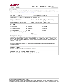
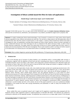
Module:6 Lecture:33 Silicon carbide Dr. N. K. Patel Module: 6 Lecture: 33 SILICON CARBIDE INTRODUCTION Silicon carbide known as carborundum, it is a compound of silicon and carbon with chemical formula SiC. It occurs in nature as the rare mineral moissanite. Silicon carbide powder has been mass-produced since 1893. Silicon carbide is the most important abrasive and was first discovered by Acheson in 1891 while he was attempting to harden clay in a homemade electric furnace. When carbon was dissolved in molten clay, it was assumed to be mixture of carbon and fused alumina called corundum and hence the name carborundum comes. Silicon carbide powder has been mass-produced since 1893 for use as an abrasive. Grains of silicon carbide can be bonded together by sintering to form very hard ceramics The first LED action was demonstrated in 1907 using SiC and also first commercial LEDs were based on SiC, yellow LEDs made from 3C-SiC were manufactured in the Soviet Union in the 1970s and blue ones from 6H-SiC in the 1980s. Large single crystals of silicon carbide can be grown by the Lely method; they can be cut into gems known as synthetic moissanite. Silicon carbide with high surface area can be produced from SiO2 contained in plant material. MANUFACTURE Raw material Basis: 1000kg of Silicon carbide Silica 1500kg Carbon 900kg NPTEL 1 Module:6 Lecture:33 Silicon carbide Dr. N. K. Patel Reaction The various reactions involved in the manufacture of silicon carbide are _______________________________________ The temperature was maintained at 20000C. Higher temperature was prevented as Sic was decomposed into graphite at high temperature. Manufacture process Silicon carbide (SiC) is now manufactured from silica and carbon. The sources of carbon are coke, pitch, petroleum cokes and anthracite. The sand contains pure silica (98 – 99.5%). 1. The Acheson process Stationary end wall Furnace gases SiC finely crystalline outer zone Electrode Movable side wall with opening for furnace gases Reaction mixture Electric supply Silicon carbide roll SiC finely coarsely crystalline inner zone Heating resistor (core) Heating resistor (core) Movable side wall with opening for furnace gases Graphite from decomposition of SiC SiC finely coarsely crystalline inner zone Graphite from decomposition of SiC SiC finely crystalline outer zone Figure: Manufacture of Silicon carbide using Acheson furnace Animation Special type of open top indirect heating resistance furnace is used for manufacture of SiC. The furnace was consisting of a movable side wall with opening for gases, electrode, heating core and permanent bed of cast iron pieces lined with fire brick on which the charge was placed. The charge was built up in the furnace around a heating core of granular carbon. The 30 – 50ft long furnace was provided with about 60 carbon electrodes which were 1metre long and 8cm. in diameter and the central core of iron connects these electrodes. The ends of the furnace were permanent and the NPTEL 2 Module:6 Lecture:33 Silicon carbide Dr. N. K. Patel sides were built up every time with the charge. The outside unreacted charge acts as an insulator. There so, excessive heat loss cannot occured. The mixture of 53.5% SiO2, 40% coke, 5% saw dust and 1.5% salt was charged to furnace until the furnace is fully charged. Saw dusts were added because it increases the porosity of the charge to permit the circulation of vapours. A typical initial current was passed between the two electrodes which were initially 6000amp at 250volts, but its resistance gradually decreased as the reaction proceeds and the final current becomes 20000amp at 75volts. After about 2hr, the current increased rapidly from 6000 to 20000amps and remains steady during the whole run of 36hr. The temperatures at the core are 22000C and remain steady for the whole 36hr until the reaction was completed. During the reaction CO was generated which was burned at the top of the furnace and escape through a movable side walls. The product was then cooled for 24hr. The side walls were pulled down after as the process was completed. Crystals of silicon were removed from the furnace. The yield is about 6000 – 8000kg per furnace. The black crystals were broken and then treated successively with sulfuric acid and sodium hydroxide solution. It was dried in a kiln and graded through a screening or sieving system into, the powders of various degrees of fitness. The graphite formed in this manner is called artificial graphite. The outer unreacted part of the charge was combined with the next charge for the furnace and next to the core some graphite formed as a result of decomposition of SiC was obtained. After complete run, which taken about 36+24=60hrs, the graphite can be separated as a by-product from silicon carbide and converted to desired shapes. Engineering aspects Effect of temperature It should be noted that the temperature of the core should not exceed 22000C otherwise silicon carbide was decomposed into graphite with the volatilization of silicon. NPTEL 3 Module:6 Lecture:33 Silicon carbide Dr. N. K. Patel 2. The ESK process A major disadvantage of the Acheson furnace is loss of by-product CO and even SO2 and dust contains in the waste gases leads to pollution. These disadvantages of Acheson process leads to the development of ESK process. The ESK furnace consists of floor electrode, gas-permeable furnace bed, gas collector, plastic sheet and heating core. Heating core used for this ESK furnace was horizontal as same in case of Acheson furnace. The mixture of coke and sand was charged by wheel loaders into reaction zone, until the zone was full of raw material or charge reached the top of the graphite columns. Graphite was placed on each electrode of furnace. ESK furnace is considerably larger than Acheson furnace. SiC finely crystalline outer zone Furnace gases SiC coarsely crystalline inner zone Graphite from decomposition of SiC Heating resistor (core) Plastic sheet SiC finely crystalline outer zone Plastic sheet Heating resistor (core) Furnace gases Graphite from decomposition of SiC SiC coarsely crystalline inner zone Reaction mixture Floor electrode Gas collection Electric supply Floor electrode Silicon carbide Gas collection Gas permeable furnace bed SiC finely crystalline outer zone Gas permeable furnace bed Figure: Manufacture of Silicon carbide using ESK furnace Animation As the reaction mixture was reached to top of the column level, horizontal heating core which is linear or U shaped, put in the position and connected to a graphite column. Then heating core was covered with remaining reaction mixture from wheel loaders, so it forms a mound shape. Further this mound has to be covered with plastic sheet to trap the evolved gases. Furnace has no walls while electrodes are located in floor. The initial current was passed, which was initially 6000amp at 250volts, after that was increased to 20000amp. The CO evolved as by-product which was trapped through plastic sheet and collected in gas collection tube continuously. After completion of reaction, switch off the power and then plastic sheet was pulled off. Unconverted or remaining reaction mixture was removed first and lumps of silicon carbide were taken out of the furnace and NPTEL 4 Module:6 Lecture:33 Silicon carbide Dr. N. K. Patel broken down with hydraulic equipment. Finally, the crystalline outer zone was further size reduction was carried out in jaw crusher and recycled to the process. The coarsely crystalline from the inner zone of the SiC roll were sorted. The top-grade material formed the largest fraction of silicon carbide yield. Engineering aspects Steps for improvement in yield Silica or sand should be of 98% pure The carbon used may be petroleum coke, metallurgical coke, anthracite etc. having low ash and sulfur contents Fe2O3 and Al2O3 in silica should be as low as possible as they catalyzed the decomposition of SiC. The carbide undergoes decomposition at 2830°C The temperature of formation of silicon carbide is about 18400C ± 300C 100 parts by weight of finest grade sand, 60parts by weight of coke and 19parts by weight of saw dust is the charge composition for a good yield of SiC Saw dust increases the porosity of the charge or escape of CO and other volatile matter during SiC formation Purity The impurities from the reaction zone were removed by introducing chlorine gas. Depending on the amount of impurities colour of product crystals varies from pale yellow or green to black. Addition of boron, titanium or zircon in small amount to the furnace charge reduces the product sensitivity to oxidation at 900 – 11000C. As described earlier in Acheson process, the reduction of silica was carried out at temperature in excess of 21000C resulting in SiC grains. PROPERTIES NPTEL Molecular formula Molecular weight Appearance Odour Boiling point : SiC : 40.10gm/mole : Colourless crystals : Odourless : 28150C dissociates 5 Module:6 Lecture:33 Silicon carbide Melting point Density Refractive index Dr. N. K. Patel : 27300C (decomposes) : 3.21gm/cm3 (all polytypes) : 2.55 (infrared, all polytypes) USES Silicon carbide is a popular abrasive in modern lapidary due to the durability and low cost of the material In composite armour As a support and shelving material in high temperature kilns such as for firing ceramics, glass fusing or casting In automobile industry In a sintered form for diesel particulate filters Used in LED Low thermal expansion coefficient, rigidity, high hardness and thermal conductivity make silicon carbide a desirable mirror material for astronomical telescopes Silicon carbide fibres are used to measure gas temperatures in an optical technique called thin filament pyrometry Important material in TRISO-coated fuel particles, which is found in high temperature gas cooled reactors and layer of silicon carbide gives structural support and is the main diffusion barrier to the release of fission products Used to produce epitaxial graphene by graphitization at high temperatures In steel manufacturing Used in applications requiring high endurance, such as car brakes, car clutches and ceramic plates in bulletproof vests Used in high-temperature and high-voltage semiconductor electronics equipments NPTEL 6
© Copyright 2026 ExpyDoc