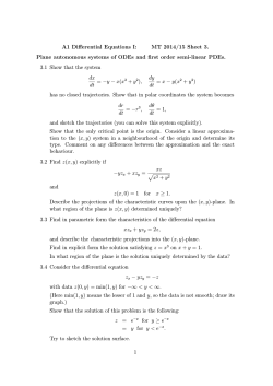
Drawing an oval gear in CREO (Pro/E) And train working with parameters, relations, using formulas, pattern, copy geometry and spinal bend. BJP 1. Go to tools Parameters. The Parameters window opens. Add two new lines: Name: small_diameter Type: Real number Value: 50 Name: large_diameter Type: Real number Value: 100 2. Start a sketch in the front plane and draw an elipse (dimensions are not relevant yet) Double click on the vertical dimension and change the value with the following text: “small_diameter”. Do the same with the large diameter. 2. Exit the sketch. Go to Measure measure length and click on the blue sketch line. In the measure length window, select “use as chain” to automatically select the perimeter of the oval shape. 3. Save the perimeter value by making the analysis a feature: 4. Press ok and start a new sketch on the front plane: Use the right end of the previous sketch as a reference. To add a reference click on: References 5. Draw a gear-tooth with the orientation vertically: I used a gear tooth which I have in my Sketcher Palette. All I have to do is to rotate, scale and place the shape on the reference. You can sketch your own shape which looks like a tooth. 6. Im going to close the sketch (so that the shape becomes yellow-ish shaded) because I want to create a solid, make the total length of the tooth a dimension (and therefore a parameter, in this case sd15) length 7. Exit the sketch and right-click on this new sketch in the modeltree and select “edit”. Now all dimensions of the sketch become visible in the main window. Right click on the dimension which represents the length of the tooth (sd15) and select “properties”. Change the name of sd15 into “tooth_width”. 8. Go to Tools Relations, fill in the following two formulas: members=(floor(abs(LENGTH:FID_48/tooth_width))) length=members*tooth_width The first formula means that the number of teeth (“members”) depends on the length (perimeter) of the oval divided by a single tooth width. Because this will probably result in a number with decimals, we are using the floor command to get the number without decimals (a so called integer) that is closest (the largest integer not greater than the real value). The second formula will give the new value of the oval perimeter that matches the total number of teeth. 9. We are going to draw a new oval that matches the number of teeth. Start a new sketch on the front plane. Again reference the oval at the right side and draw a new oval with this reference. Now we are going to use the Perimeter command to make sure the perimeter of this new oval is “length”: Start the Perimeter command, click once on the new blue oval line, middle-click and then leftclick on the horizontal dimension. You will now see the value of the perimeter in red. You can modify this value by double-clicking on this value and type: “length”. 10. Now the Perimeter of the new oval has the right size to contain a fixed number of teeth, but the hor/ver proportion is not the same. Therefore we are going to to add a formula in the sketcher relations: While still being in sketcher mode, go to Tools Relations and fill in the following formula: sd1=sd0*(vertical_diameter/horizontal_diameter) Now the shape of the new oval has the same shape as the first one. You can guess what this formula does. Of course change parameter names when the ones in your sketch differ from the one here. 11. While still in the same sketch, draw a vertical line, starting from the earlier added reference and rename the dimension value with “length”. Now exit the sketch. 12. Add a new plane parallel to the top-plane and trough the top-end of the vertical line: 13. Now we are going to extrude the tooth sketch. First we are going to define a parameter for the extrude thickness: Go to Tools Parameters and ad a new parameter called “width”, enter 10 as thickness value. Now Select the tooth sketch (sketch 2) in the modeltree, and go to model extrude. (If you get an error, you might need to set model accuracy a decimal higher: go to file Prepare Model Properties change accuracy: change to 0.00012 instead of 0.0012) Extrude to the back and enter “width” as depth value 14. Now we are going to pattern the tooth: Select extrude 1 in the modeltree, right-click: pattern. In the Pattern tab, select “direction” as pattern type, and select top plane to define this direction. Enter “tooth_width” to define spacing between pattern members . Apply the pattern. 15. Go to the modeltree and right-click on the new pattern edit. Rightclick on “2 extrudes” and go to properties, change the name to “members” If you get an error on this, change the name into e.g. “members2” and do the same in the parameters window afterwards. 16. Now we are going to bend this rack around the second oval. Hide sketch 1 and go to model engineering Spinal bend: 1. Press Done 2. Select the side of the rack 3. Select the blue line of the second oval, press control, and click on the other half of the blue line 4. Select “ok” in the little select window 5. Select “start point” and make sure the startpoint is at the bottom of the rack, otherwise click on a point on the oval near the rack 6. Press Accept and press Done 7. Select the plane created in step 12. Now we have a spinal bend. 17. Now we want to add a core to the newly created gear. However the spinal bend transforms the solid into something spacy and we cannot simply extrude a core inside the oval shape (also creating a solid core prior to the spinal bend operation will cause errors). Therefore we are going to copy the side surface of the spinal bend to create a new solid. Select the side surface, Ctrl+left-click on the other half of the side surface. Press ctrl+c and ctrl+v (copy and paste) to paste the new surface. 18. Click on the new surface once and go to model Thicken (front direction). Again use “tooth_width” as value for thickness. 19. Remove the old gear (spinal bend) by adding an extrude feature that removes material. Make sure this extrude is always larger than the outer edges of the gear by adding references to these edges or using “length” for height and length dimension. 20. Create a new sketch on the front plane and place a line on the inner edges of the new oval gear with help of the “Project” function. Also reference to the front- and right plane and create a circle in the middle of the oval (this will become the gear-hole). Exit the sketch and extrude to the correct direction with “tooth_width” as thickness. If you like, you can create a new parameter “hole_diameter” and link this to the hole dimension. Hide sketches that are still visible and go to view status save status to make sure the sketches are still hidden when you open the part.
© Copyright 2026 ExpyDoc