Network Configuration Example
Configuring Media Access Control Security
(MACsec) over an MPLS Circuit Cross-Connect
(CCC)
Published: 2014-06-26
Copyright © 2014, Juniper Networks, Inc.
Juniper Networks, Inc.
1194 North Mathilda Avenue
Sunnyvale, California 94089
USA
408-745-2000
www.juniper.net
Copyright © 2014, Juniper Networks, Inc. All rights reserved.
Juniper Networks, Junos, Steel-Belted Radius, NetScreen, and ScreenOS are registered trademarks of Juniper Networks, Inc. in the United
States and other countries. The Juniper Networks Logo, the Junos logo, and JunosE are trademarks of Juniper Networks, Inc. All other
trademarks, service marks, registered trademarks, or registered service marks are the property of their respective owners.
Juniper Networks assumes no responsibility for any inaccuracies in this document. Juniper Networks reserves the right to change, modify,
transfer, or otherwise revise this publication without notice.
Network Configuration Example Configuring Media Access Control Security (MACsec) over an MPLS Circuit Cross-Connect (CCC)
Copyright © 2014, Juniper Networks, Inc.
All rights reserved.
The information in this document is current as of the date on the title page.
YEAR 2000 NOTICE
Juniper Networks hardware and software products are Year 2000 compliant. Junos OS has no known time-related limitations through the
year 2038. However, the NTP application is known to have some difficulty in the year 2036.
END USER LICENSE AGREEMENT
The Juniper Networks product that is the subject of this technical documentation consists of (or is intended for use with) Juniper Networks
software. Use of such software is subject to the terms and conditions of the End User License Agreement (“EULA”) posted at
http://www.juniper.net/support/eula.html. By downloading, installing or using such software, you agree to the terms and conditions of
that EULA.
ii
Copyright © 2014, Juniper Networks, Inc.
Table of Contents
About the Documentation . . . . . . . . . . . . . . . . . . . . . . . . . . . . . . . . . . . . . . . . . . . . ix
Documentation and Release Notes . . . . . . . . . . . . . . . . . . . . . . . . . . . . . . . . . . ix
Supported Platforms . . . . . . . . . . . . . . . . . . . . . . . . . . . . . . . . . . . . . . . . . . . . . ix
Documentation Conventions . . . . . . . . . . . . . . . . . . . . . . . . . . . . . . . . . . . . . . . ix
Documentation Feedback . . . . . . . . . . . . . . . . . . . . . . . . . . . . . . . . . . . . . . . . . xi
Requesting Technical Support . . . . . . . . . . . . . . . . . . . . . . . . . . . . . . . . . . . . . xii
Self-Help Online Tools and Resources . . . . . . . . . . . . . . . . . . . . . . . . . . . xii
Opening a Case with JTAC . . . . . . . . . . . . . . . . . . . . . . . . . . . . . . . . . . . . . xii
Chapter 1
Media Access Control Security (MACsec) over an MPLS Circuit
Cross-Connect (CCC) Configuration . . . . . . . . . . . . . . . . . . . . . . . . . . . . . . . . . 15
About This Network Configuration Example . . . . . . . . . . . . . . . . . . . . . . . . . . . . . . 15
Understanding Media Access Control Security (MACsec) Benefits . . . . . . . . . . . . 15
Example: Configuring Media Access Control Security (MACsec) over an MPLS
Circuit Cross-Connect (CCC) . . . . . . . . . . . . . . . . . . . . . . . . . . . . . . . . . . . . . . 16
Copyright © 2014, Juniper Networks, Inc.
iii
Configuring Media Access Control Security (MACsec) over an MPLS Circuit Cross-Connect (CCC)
iv
Copyright © 2014, Juniper Networks, Inc.
List of Figures
Chapter 1
Media Access Control Security (MACsec) over an MPLS Circuit
Cross-Connect (CCC) Configuration . . . . . . . . . . . . . . . . . . . . . . . . . . . . . . . . . 15
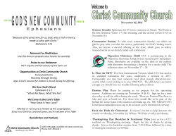
Figure 1: MPLS Diagram Between Site A and Site B . . . . . . . . . . . . . . . . . . . . . . . . 18
Copyright © 2014, Juniper Networks, Inc.
v
Configuring Media Access Control Security (MACsec) over an MPLS Circuit Cross-Connect (CCC)
vi
Copyright © 2014, Juniper Networks, Inc.
List of Tables
About the Documentation . . . . . . . . . . . . . . . . . . . . . . . . . . . . . . . . . . . . . . . . . . ix
Table 1: Notice Icons . . . . . . . . . . . . . . . . . . . . . . . . . . . . . . . . . . . . . . . . . . . . . . . . . . x
Table 2: Text and Syntax Conventions . . . . . . . . . . . . . . . . . . . . . . . . . . . . . . . . . . . . x
Chapter 1
Media Access Control Security (MACsec) over an MPLS Circuit
Cross-Connect (CCC) Configuration . . . . . . . . . . . . . . . . . . . . . . . . . . . . . . . . . 15
Table 3: Components of the MPLS Topology . . . . . . . . . . . . . . . . . . . . . . . . . . . . . 18
Table 4: MACsec Connectivity Association Summary . . . . . . . . . . . . . . . . . . . . . . . 19
Table 5: VLANs Summary . . . . . . . . . . . . . . . . . . . . . . . . . . . . . . . . . . . . . . . . . . . . 20
Copyright © 2014, Juniper Networks, Inc.
vii
Configuring Media Access Control Security (MACsec) over an MPLS Circuit Cross-Connect (CCC)
viii
Copyright © 2014, Juniper Networks, Inc.
About the Documentation
•
Documentation and Release Notes on page ix
•
Supported Platforms on page ix
•
Documentation Conventions on page ix
•
Documentation Feedback on page xi
•
Requesting Technical Support on page xii
Documentation and Release Notes
®
To obtain the most current version of all Juniper Networks technical documentation,
see the product documentation page on the Juniper Networks website at
http://www.juniper.net/techpubs/.
If the information in the latest release notes differs from the information in the
documentation, follow the product Release Notes.
Juniper Networks Books publishes books by Juniper Networks engineers and subject
matter experts. These books go beyond the technical documentation to explore the
nuances of network architecture, deployment, and administration. The current list can
be viewed at http://www.juniper.net/books.
Supported Platforms
For the features described in this document, the following platforms are supported:
•
EX Series
Documentation Conventions
Table 1 on page x defines notice icons used in this guide.
Copyright © 2014, Juniper Networks, Inc.
ix
Configuring Media Access Control Security (MACsec) over an MPLS Circuit Cross-Connect (CCC)
Table 1: Notice Icons
Icon
Meaning
Description
Informational note
Indicates important features or instructions.
Caution
Indicates a situation that might result in loss of data or hardware damage.
Warning
Alerts you to the risk of personal injury or death.
Laser warning
Alerts you to the risk of personal injury from a laser.
Tip
Indicates helpful information.
Best practice
Alerts you to a recommended use or implementation.
Table 2 on page x defines the text and syntax conventions used in this guide.
Table 2: Text and Syntax Conventions
Convention
Description
Examples
Bold text like this
Represents text that you type.
To enter configuration mode, type the
configure command:
user@host> configure
Fixed-width text like this
Italic text like this
Italic text like this
x
Represents output that appears on the
terminal screen.
user@host> show chassis alarms
•
Introduces or emphasizes important
new terms.
•
•
Identifies guide names.
A policy term is a named structure
that defines match conditions and
actions.
•
Identifies RFC and Internet draft titles.
•
Junos OS CLI User Guide
•
RFC 1997, BGP Communities Attribute
Represents variables (options for which
you substitute a value) in commands or
configuration statements.
No alarms currently active
Configure the machine’s domain name:
[edit]
root@# set system domain-name
domain-name
Copyright © 2014, Juniper Networks, Inc.
About the Documentation
Table 2: Text and Syntax Conventions (continued)
Convention
Description
Examples
Text like this
Represents names of configuration
statements, commands, files, and
directories; configuration hierarchy levels;
or labels on routing platform
components.
•
To configure a stub area, include the
stub statement at the [edit protocols
ospf area area-id] hierarchy level.
•
The console port is labeled CONSOLE.
< > (angle brackets)
Encloses optional keywords or variables.
stub <default-metric metric>;
| (pipe symbol)
Indicates a choice between the mutually
exclusive keywords or variables on either
side of the symbol. The set of choices is
often enclosed in parentheses for clarity.
broadcast | multicast
# (pound sign)
Indicates a comment specified on the
same line as the configuration statement
to which it applies.
rsvp { # Required for dynamic MPLS only
[ ] (square brackets)
Encloses a variable for which you can
substitute one or more values.
community name members [
community-ids ]
Indention and braces ( { } )
Identifies a level in the configuration
hierarchy.
; (semicolon)
Identifies a leaf statement at a
configuration hierarchy level.
(string1 | string2 | string3)
[edit]
routing-options {
static {
route default {
nexthop address;
retain;
}
}
}
GUI Conventions
Bold text like this
Represents graphical user interface (GUI)
items you click or select.
> (bold right angle bracket)
Separates levels in a hierarchy of menu
selections.
•
In the Logical Interfaces box, select
All Interfaces.
•
To cancel the configuration, click
Cancel.
In the configuration editor hierarchy,
select Protocols>Ospf.
Documentation Feedback
We encourage you to provide feedback, comments, and suggestions so that we can
improve the documentation. You can provide feedback by using either of the following
methods:
•
Online feedback rating system—On any page at the Juniper Networks Technical
Documentation site at http://www.juniper.net/techpubs/index.html, simply click the
stars to rate the content, and use the pop-up form to provide us with information about
your experience. Alternately, you can use the online feedback form at
https://www.juniper.net/cgi-bin/docbugreport/.
Copyright © 2014, Juniper Networks, Inc.
xi
Configuring Media Access Control Security (MACsec) over an MPLS Circuit Cross-Connect (CCC)
•
E-mail—Send your comments to [email protected]. Include the document
or topic name, URL or page number, and software version (if applicable).
Requesting Technical Support
Technical product support is available through the Juniper Networks Technical Assistance
Center (JTAC). If you are a customer with an active J-Care or JNASC support contract,
or are covered under warranty, and need post-sales technical support, you can access
our tools and resources online or open a case with JTAC.
•
JTAC policies—For a complete understanding of our JTAC procedures and policies,
review the JTAC User Guide located at
http://www.juniper.net/us/en/local/pdf/resource-guides/7100059-en.pdf.
•
Product warranties—For product warranty information, visit
http://www.juniper.net/support/warranty/.
•
JTAC hours of operation—The JTAC centers have resources available 24 hours a day,
7 days a week, 365 days a year.
Self-Help Online Tools and Resources
For quick and easy problem resolution, Juniper Networks has designed an online
self-service portal called the Customer Support Center (CSC) that provides you with the
following features:
•
Find CSC offerings: http://www.juniper.net/customers/support/
•
Search for known bugs: http://www2.juniper.net/kb/
•
Find product documentation: http://www.juniper.net/techpubs/
•
Find solutions and answer questions using our Knowledge Base: http://kb.juniper.net/
•
Download the latest versions of software and review release notes:
http://www.juniper.net/customers/csc/software/
•
Search technical bulletins for relevant hardware and software notifications:
http://kb.juniper.net/InfoCenter/
•
Join and participate in the Juniper Networks Community Forum:
http://www.juniper.net/company/communities/
•
Open a case online in the CSC Case Management tool: http://www.juniper.net/cm/
To verify service entitlement by product serial number, use our Serial Number Entitlement
(SNE) Tool: https://tools.juniper.net/SerialNumberEntitlementSearch/
Opening a Case with JTAC
You can open a case with JTAC on the Web or by telephone.
xii
•
Use the Case Management tool in the CSC at http://www.juniper.net/cm/.
•
Call 1-888-314-JTAC (1-888-314-5822 toll-free in the USA, Canada, and Mexico).
Copyright © 2014, Juniper Networks, Inc.
About the Documentation
For international or direct-dial options in countries without toll-free numbers, see
http://www.juniper.net/support/requesting-support.html.
Copyright © 2014, Juniper Networks, Inc.
xiii
Configuring Media Access Control Security (MACsec) over an MPLS Circuit Cross-Connect (CCC)
xiv
Copyright © 2014, Juniper Networks, Inc.
CHAPTER 1
Media Access Control Security (MACsec)
over an MPLS Circuit Cross-Connect
(CCC) Configuration
•
About This Network Configuration Example on page 15
•
Understanding Media Access Control Security (MACsec) Benefits on page 15
•
Example: Configuring Media Access Control Security (MACsec) over an MPLS Circuit
Cross-Connect (CCC) on page 16
About This Network Configuration Example
This network configuration example provides an overview of Media Access Control
Security (MACsec) and a sample use case showing how MACsec can be enabled on a
circuit cross-connect (CCC) to secure traffic through an MPLS cloud between users at
different sites that frequently exchange financially-sensitive data.
Understanding Media Access Control Security (MACsec) Benefits
Media Access Control Security (MACsec) is an industry-standard security technology
that provides secure communication for all traffic on Ethernet links. MACsec provides
point-to-point security on Ethernet links between directly connected nodes and is capable
of identifying and preventing most security threats, including denial of service, intrusion,
man-in-the-middle, masquerading, passive wiretapping, and playback attacks. MACsec
is standardized in IEEE 802.1AE.
MACsec allows you to secure an Ethernet link for almost all traffic, including frames from
the Link Layer Discovery Protocol (LLDP), Link Aggregation Control Protocol (LACP),
Dynamic Host Configuration Protocol (DHCP), Address Resolution Protocol (ARP), and
other protocols that are not typically secured on an Ethernet link because of limitations
with other security solutions. MACsec can be used in combination with other security
protocols such as IP Security (IPsec) and Secure Sockets Layer (SSL) to provide
end-to-end network security.
When MACsec is enabled, an 8-byte header and a 16-byte tail are appended to all Ethernet
frames traversing the MACsec-secured link. The header and tail are checked by the
receiving interface to ensure that the data was not compromised while traversing the
Copyright © 2014, Juniper Networks, Inc.
15
Configuring Media Access Control Security (MACsec) over an MPLS Circuit Cross-Connect (CCC)
link. If the data integrity check detects anything irregular about the traffic, the traffic is
dropped.
MACsec can also be used to encrypt traffic on the Ethernet link. The encryption used by
MACsec ensures that the data in the Ethernet frame cannot be viewed by anybody
monitoring traffic on the link. MACsec encryption is optional and user-configurable; you
can enable MACsec to ensure the data integrity checks are performed while still sending
unencrypted data “in the clear” over the MACsec-secured link, if desired.
MACsec provides industry-standard security for Layer 2 traffic, and is useful in any scenario
where sensitive Layer 2 traffic needs to be sent across the network securely.
Related
Documentation
•
Example: Configuring Media Access Control Security (MACsec) over an MPLS Circuit
Cross-Connect (CCC) on page 16
Example: Configuring Media Access Control Security (MACsec) over an MPLS Circuit
Cross-Connect (CCC)
This example shows how to enable Media Access Control security (MACsec) to secure
sensitive traffic travelling from a user at one site to a user at another site over a basic
MPLS circuit cross-connect (CCC).
•
Requirements on page 16
•
Overview and Topology on page 17
•
Configuring MPLS on page 20
•
Configuring MACsec on page 26
•
Configuring VLANs to Direct Traffic Onto the MACsec-secured CCC on page 29
•
Verification on page 32
Requirements
This example uses the following hardware and software components:
16
•
Three EX4550 switches used as the PE and provider switches in the MPLS network.
•
One EX4550 switch used as the CE switch connecting site A to the MPLS network.
•
One EX4200 switch that has installed an SFP+ MACsec uplink module used as the CE
switch connecting site B to the MPLS network.
•
Junos OS Release 12.2R1 or later running on all EX4550 switches in the MPLS network
(PE1, PE2, or the provider switch).
•
Junos OS Release 13.2X50-D15 (controlled version) or later running on the CE switch
at site A and the CE switch at site B.
Copyright © 2014, Juniper Networks, Inc.
Chapter 1: Media Access Control Security (MACsec) over an MPLS Circuit Cross-Connect (CCC) Configuration
NOTE: The controlled version of Junos OS software must be downloaded
to enable MACsec. MACsec software support is not available in the
domestic version of Junos OS software, which is installed on the switch by
default. The controlled version of Junos OS software includes all features
and functionality available in the domestic version of Junos OS, while also
supporting MACsec. See Understanding Media Access Control Security
(MACsec) for additional information on MACsec software requirements.
•
A MACsec feature license installed on the CE switch at site A and the CE switch at site
B.
NOTE: To purchase a software license for MACsec, contact your Juniper
Networks sales representative
(http://www.juniper.net/us/en/contact-us/sales-offices). The Juniper sales
representative will provide you with a feature license file and a license key.
You will be asked to supply the chassis serial number of your switch; you
can obtain the serial number by running the show virtual-chassis or show
chassis hardware command.
Overview and Topology
In this example, financially-sensitive company data is often sent between a user at site
A and a user at site B. The company wants to ensure that all network traffic travelling
from the user at site A to the user at site B is highly-secure and cannot be viewed or
corrupted by an attacker. The company is using the industry-standard Layer 2 security
provided by MACsec, which provides encryption to ensure data cannot be viewed by
attackers and integrity checks to ensure transmitted data isn’t corrupted, to secure all
traffic travelling on the CCC through the MPLS cloud connecting the sites. VLANs are
configured at both sites to ensure traffic travelling between the two users traverses the
sites over the MACsec-secured CCC.
The MPLS network in this example includes two provider edge (PE) switches—PE1 and
PE2—and one provider (transit) switch. PE1 connects the customer edge (CE) switch at
site A to the MPLS network and PE2 connects the CE switch at site B to the MPLS network.
MACsec is enabled on the CCC connecting the CE switches at site A and site B to secure
traffic travelling between the sites over the CCC. A VLAN that includes the interfaces
that connect the users to the CE switches, interface ge-0/0/0 on the CE switch at site
A and interface ge-0/0/2 on the CE switch at site B, and the interfaces that connect the
CE switches to the MPLS cloud (ge-0/0/0 on the site A CE switch and xe-0/1/0 on the
site B CE switch), is used to direct all traffic between the users onto the MACsec-secured
CCC.
Figure 1 on page 18 shows the topology used in this example. The MACsec-secured CCC
traffic is labeled MACsec CCC in the figure.
Copyright © 2014, Juniper Networks, Inc.
17
Configuring Media Access Control Security (MACsec) over an MPLS Circuit Cross-Connect (CCC)
Table 3 on page 18 provides a summary of the MPLS network components in this topology.
Table 4 on page 19 provides a summary of the MACsec connectivity association used in
this topology. MACsec is enabled by creating a connectivity association on the interfaces
at each end of a link. MACsec is enabled when the interfaces at each end of the link
exchange pre-shared keys—the pre-shared keys are defined in the connectivity
association—to secure the link for MACsec.
Table 5 on page 20 provides a summary of the VLAN used in this topology. The VLAN is
used in this topology to direct all communication from the user at site A to the user at
Site B onto the MACsec-secured CCC.
Table 3: Components of the MPLS Topology
Component
Description
PE1
PE switch.
lo0:
•
IP address: 130.1.1.1/32
•
Participates in OSPF and RSVP.
ge-0/0/0:
•
Customer edge interface connecting site A to the MPLS network.
•
CCC connecting to xe-0/1/1 on PE2
ge-0/0/1:
18
•
Core interface connecting PE1 to the provider switch.
•
IP address: 10.1.5.2/24
•
Participates in OSPF, RSVP, and MPLS.
Copyright © 2014, Juniper Networks, Inc.
Chapter 1: Media Access Control Security (MACsec) over an MPLS Circuit Cross-Connect (CCC) Configuration
Table 3: Components of the MPLS Topology (continued)
Component
Description
Provider
Provider switch.
lo0:
•
IP address: 130.1.1.2/32
•
Participates in OSPF and RSVP.
ge-0/0/10:
•
Core interface connecting the provider switch to PE1.
•
IP address: 10.1.5.1/24
•
Participates in OSPF, RSVP, and MPLS.
xe-0/0/0:
PE2
•
Core interface connecting the provider switch to PE2.
•
IP address: 10.1.9.1/24
•
Participates in OSPF, RSVP, and MPLS.
PE switch.
lo0:
•
IP address: 130.1.1.3/32
•
Participates in OSPF and RSVP.
xe-0/1/0
•
Core interface connecting PE2 to the provider switch.
•
IP address: 10.1.9.2/24
•
Participates in OSPF, RSVP, and MPLS.
xe-0/1/1
•
Customer edge interface connecting site B to the MPLS network.
•
CCC connecting to ge-0/0/0 on PE1.
lsp_to_pe2_xe1 label
switched path
Label switched path from PE1 to PE2.
lsp_to_pe1_ge0 label
switched path
Label switched path from PE2 to PE1.
Table 4: MACsec Connectivity Association Summary
Connectivity Association
Description
ccc-macsec
Connectivity association enabling MACsec on CCC connecting Site A to Site B.
The connectivity association is enabled on the following interfaces:
Copyright © 2014, Juniper Networks, Inc.
•
Site A CE switch: ge-0/0/0
•
Site B CE switch: xe-0/1/0
19
Configuring Media Access Control Security (MACsec) over an MPLS Circuit Cross-Connect (CCC)
Table 5: VLANs Summary
VLAN
Description
macsec
VLAN directing traffic between the user at site A and the user at site B onto the MACsec-secured CCC.
The VLAN includes the following interfaces.
•
Site A CE switch: ge-0/0/0
•
Site A CE switch: ge-0/0/1
•
Site B CE switch: xe-0/1/0
•
Site B CE switch: ge-0/0/2
Configuring MPLS
This section documents the steps needed to configure MPLS on each switch in the MPLS
network.
It includes the following sections:
•
Configuring MPLS on PE1 on page 20
•
Configuring MPLS on the Provider Switch on page 22
•
Configuring MPLS on PE2 on page 24
•
Results on page 25
Configuring MPLS on PE1
CLI Quick
Configuration
To quickly create the MPLS configuration on the PE1 switch, use the following commands:
Step-by-Step
Procedure
To configure MPLS on PE1:
[edit]
set protocols ospf traffic-engineering
set protocols ospf area 0.0.0.0 interface lo0.0
set protocols ospf area 0.0.0.0 interface ge-0/0/1.0
set protocols mpls label-switched-path lsp_to_pe2_xe1 to 130.1.1.3
set protocols mpls interface ge-0/0/1.0
set protocols rsvp interface lo0.0
set protocols rsvp interface ge-0/0/1.0
set interfaces lo0 unit 0 family inet address 130.1.1.1/32
set interfaces ge-0/0/1 unit 0 family inet address 10.1.5.2/24
set interfaces ge-0/0/1 unit 0 family mpls
set interfaces ge-0/0/0 unit 0 family ccc
set protocols connections remote-interface-switch ge-1-to-pe2 interface ge-0/0/0.0
set protocols connections remote-interface-switch ge-1-to-pe2 transmit-lsp lsp_to_pe2_xe1
set protocols connections remote-interface-switch ge-1-to-pe2 receive-lsp lsp_to_pe1_ge0
1.
Configure OSPF with traffic engineering enabled:
[edit protocols]
user@switch-PE1# set ospf traffic-engineering
2.
Configure OSPF on the loopback address and the core interfaces:
[edit protocols]
user@switch-PE1# set ospf area 0.0.0.0 interface lo0.0
user@switch-PE1# set ospf area 0.0.0.0 interface ge-0/0/1.0
3.
20
Configure MPLS on this switch, PE1, with an LSP to PE2:
Copyright © 2014, Juniper Networks, Inc.
Chapter 1: Media Access Control Security (MACsec) over an MPLS Circuit Cross-Connect (CCC) Configuration
[edit protocols]
user@switch-PE1# set mpls label-switched-path lsp_to_pe2_xe1 to 130.1.1.3
4.
Configure MPLS on the core interfaces:
[edit protocols]
user@switch-PE1# set mpls interface ge-0/0/1.0
5.
Configure RSVP on the loopback interface and the core interfaces:
[edit protocols]
user@switch-PE1# set rsvp interface lo0.0
user@switch-PE1# set rsvp interface ge-0/0/1.0
6.
Configure IP addresses for the loopback interface and the core interfaces:
[edit]
user@switch-PE1# set interfaces lo0 unit 0 family inet address 130.1.1.1/32
user@switch-PE1# set interfaces ge-0/0/1 unit 0 family inet address 10.1.5.2/24
7.
Configure family mpls on the logical unit of the core interface addresses:
[edit]
user@switch-PE1# set interfaces ge-0/0/1 unit 0 family mpls
8.
Configure the logical unit of the customer edge interface as a CCC:
[edit interfaces ge-0/0/0 unit 0]
user@PE-1# set family ccc
9.
Configure the interface-based CCC from PE-1 to PE-2:
[edit protocols]
user@PE-1# set connections remote-interface-switch ge-1-to-pe2 interface
ge-0/0/0.0user@PE-1# set connections remote-interface-switch ge-1-to-pe2 transmit-lsp
lsp_to_pe2_xe1
user@PE-1# set connections remote-interface-switch ge-1-to-pe2 receive-lsp lsp_to_pe1_ge0
Results
Display the results of the configuration:
user@PE-1> show configuration
interfaces {
ge-0/0/0 {
unit 0 {
family ccc;
}
}
}
ge-0/0/1{
unit 0 {
family inet {
address 130.1.5.2/24;
}
family mpls;
}
}
lo0 {
unit 0 {
family inet {
address 130.1.1.1/32;
}
}
}
protocols {
rsvp {
Copyright © 2014, Juniper Networks, Inc.
21
Configuring Media Access Control Security (MACsec) over an MPLS Circuit Cross-Connect (CCC)
interface lo0.0;
interface ge-0/0/1.0;
}
mpls {
label-switched-path lsp_to_pe2_xe1 {
to 130.1.1.3;
}
interface ge-0/0/1.0;
}
ospf {
traffic-engineering;
area 0.0.0.0 {
interface lo0.0;
interface ge-0/0/1.0;
}
}
connections {
remote-interface-switch ge-1-to-pe2 {
interface ge-0/0/0.0;
transmit-lsp lsp_to_pe2_xe1;
receive-lsp lsp_to_pe1_ge0;
}
}
Configuring MPLS on the Provider Switch
CLI Quick
Configuration
To quickly create the MPLS configuration on the provider switch, use the following
commands:
[edit]
set protocols ospf traffic-engineering
set protocols ospf area 0.0.0.0 interface lo0.0
set protocols ospf area 0.0.0.0 interface ge-0/0/10.0
set protocols ospf area 0.0.0.0 interface xe-0/0/0.0
set protocols mpls interface ge-0/0/10.0
set protocols mpls interface xe-0/0/0.0
set protocols mpls label-switched-path lsp_to_pe2_xe1 to 130.1.1.3
set protocols rsvp interface lo0.0
set protocols rsvp interface ge-0/0/10.0
set protocols rsvp interface xe-0/0/0.0
set interfaces lo0 unit 0 family inet address 130.1.1.2/32
set interfaces ge-0/0/10 unit 0 family inet address 10.1.5.1/24
set interfaces ge-0/0/10 unit 0 family mpls
set interfaces xe-0/0/0 unit 0 family inet address 10.1.9.1/24
set interfaces xe-0/0/0 unit 0 family mpls
Step-by-Step
Procedure
To configure the provider switch:
1.
Configure OSPF with traffic engineering enabled:
[edit protocols]
user@switch-P# set ospf traffic-engineering
2.
Configure OSPF on the loopback interface and the core interfaces:
[edit protocols]
user@switch-P# set ospf area 0.0.0.0 interface lo0.0
user@switch-P# set ospf area 0.0.0.0 interface ge-0/0/10.0
user@switch-P# set ospf area 0.0.0.0 interface xe-0/0/0.0
22
Copyright © 2014, Juniper Networks, Inc.
Chapter 1: Media Access Control Security (MACsec) over an MPLS Circuit Cross-Connect (CCC) Configuration
3.
Configure MPLS on the core interfaces on the switch:
[edit protocols]
user@switch-P# set mpls interface ge-0/0/10.0
user@switch-P# set mpls interface xe-0/0/0.0
4.
Configure RSVP on the loopback interface and the core interfaces:
[edit protocols]
user@switch-P# set rsvp interface lo0.0
user@switch-P# set rsvp interface ge-0/0/10.0
user@switch-P# set rsvp interface xe-0/0/0.0
5.
Configure IP addresses for the loopback interface and the core interfaces:
[edit]
user@switch-P# set interfaces lo0 unit 0 family inet address 130.1.1.2/32
user@switch-P# set interfaces ge-0/0/10 unit 0 family inet address 10.1.5.1/24
user@switch-P# set interfaces xe-0/0/0 unit 0 family inet address 10.1.9.1/24
6.
Configure family mpls on the logical unit of the core interface addresses:
[edit]
user@switch-P# set interfaces ge-0/0/10 unit 0 family mpls
user@switch-P# set interfaces xe-0/0/0 unit 0 family mpls
7.
Configure the LSP to PE2:
[edit]
user@switch-P# set protocols mpls label-switched-path lsp_to_pe2_xe1 to 130.1.1.3
Results
Display the results of the configuration:
user@switch-P> show configuration
interfaces {
ge-0/0/10 {
unit 0 {
family inet {
address 10.1.5.1/24;
}
family mpls;
}
}
xe-0/0/0 {
unit 0 {
family inet {
address 10.1.9.1/24;
}
family mpls;
}
}
lo0 {
unit 0 {
family inet {
address 130.1.1.2/32;
}
}
}
protocols {
rsvp {
interface lo0.0;
interface ge-0/0/10.0;
Copyright © 2014, Juniper Networks, Inc.
23
Configuring Media Access Control Security (MACsec) over an MPLS Circuit Cross-Connect (CCC)
interface xe-0/0/0.0;
}
mpls {
label-switched-path lsp_to_pe2_xe1 {
to 130.1.1.3;
}
interface ge-0/0/10.0;
interface xe-0/0/0.0;
}
ospf {
traffic-engineering;
area 0.0.0.0 {
interface lo0.0;
}
interface ge-0/0/10.0;
interface xe-0/0/0.0;
}
}
Configuring MPLS on PE2
CLI Quick
Configuration
To quickly create the MPLS configuration on PE2, use the following commands:
Step-by-Step
Procedure
To configure PE2:
[edit]
set protocols ospf traffic-engineering
set protocols ospf area 0.0.0.0 interface lo0.0
set protocols ospf area 0.0.0.0 interface xe-0/1/0.0
set protocols mpls label-switched-path lsp_to_pe1_ge0 to 130.1.1.1
set protocols mpls interface xe-0/1/0.0
set protocols rsvp interface lo0.0
set protocols rsvp interface xe-0/1/0.0
set interfaces lo0 unit 0 family inet address 130.1.1.3/32
set interfaces xe-0/1/0 unit 0 family inet address 10.1.9.2/24
set interfaces xe-0/1/0 unit 0 family mpls
set interfaces xe-0/1/1 unit 0 family ccc
set protocols connections remote-interface-switch xe-1-to-pe1 interface xe-0/1/1.0
set protocols connections remote-interface-switch xe-1-to-pe1 transmit-lsp lsp_to_pe1_ge0
set protocols connections remote-interface-switch xe-1-to-pe1 receive-lsp lsp_to_pe2_xe1
1.
Configure OSPF with traffic engineering enabled:
[edit protocols]
user@switch-PE2# set ospf traffic-engineering
2.
Configure OSPF on the loopback interface and the core interface:
[edit protocols]
user@switch-PE2# set ospf area 0.0.0.0 interface lo0.0
user@switch-PE2# set ospf area 0.0.0.0 interface xe-0/1/0.0
3.
Configure MPLS on this switch (PE-2) with a label-switched path (LSP) to the other
PE switch (PE-1):
[edit protocols]
user@switch-PE2# set mpls label-switched-path lsp_to_pe1_ge0 to 130.1.1.1
4.
Configure MPLS on the core interface:
[edit protocols]
user@switch-PE2# set mpls interface xe-0/1/0.0
24
Copyright © 2014, Juniper Networks, Inc.
Chapter 1: Media Access Control Security (MACsec) over an MPLS Circuit Cross-Connect (CCC) Configuration
5.
Configure RSVP on the loopback interface and the core interface:
[edit protocols]
user@switch-PE2# set rsvp interface lo0.0
user@switch-PE2# set rsvp interface xe-0/1/0.0
6.
Configure IP addresses for the loopback interface and the core interface:
[edit]
user@switch-PE2# set interfaces lo0 unit 0 family inet address 130.1.1.3/32
user@switch-PE2# set interfaces xe-0/1/0 unit 0 family inet address 10.1.9.2/24
7.
Configure family mpls on the logical unit of the core interface:
[edit]
user@switch-PE2# set interfaces xe-0/1/0 unit 0 family mpls
8.
Configure the logical unit of the customer edge interface as a CCC:
[edit interfaces xe-0/1/1 unit 0]
user@switch-PE2# set family ccc
9.
Configure the interface-based CCC between the primary edge switches:
[edit protocols]
user@switch-PE2# set connections remote-interface-switch xe-1-to-pe1 interface xe-0/1/1.0
user@switch-PE2# set connections remote-interface-switch xe-1-to-pe1 transmit-lsp
lsp_to_pe1_ge0
user@switch-PE2# set connections remote-interface-switch xe-1-to-pe1 receive-lsp
lsp_to_pe2_xe1
Results
Display the results of the configuration:
user@switch-PE2> show configuration
interfaces {
xe-0/1/0 {
unit 0 {
family inet {
address 10.1.9.2/24;
}
family mpls;
}
}
xe-0/1/1 {
unit 0 {
family ccc;
}
}
lo0 {
unit 0 {
family inet {
address 130.1.1.3/32;
}
}
}
protocols {
rsvp {
interface lo0.0;
interface xe-0/1/0.0;
}
Copyright © 2014, Juniper Networks, Inc.
25
Configuring Media Access Control Security (MACsec) over an MPLS Circuit Cross-Connect (CCC)
mpls {
label-switched-path lsp_to_pe1_ge0 {
to 130.1.1.1;
}
interface xe-0/1/0.0;
}
ospf {
traffic-engineering;
area 0.0.0.0 {
interface lo0.0;
interface xe-0/1/0.0;
}
}
connections {
remote-interface-switch xe-1-to-pe1 {
interface xe-0/1/1.0;
transmit-lsp lsp_to_pe1_ge0;
receive-lsp lsp_to_pe2_xe1;
}
}
Configuring MACsec
This section documents the steps needed to configure MACsec on each switch in the
topology.
It includes the following sections:
26
•
Configuring MACsec on the Site A CE Switch to Secure Traffic to Site B on page 27
•
Configuring MACsec on the Site B CE Switch to Secure Traffic to Site A on page 28
Copyright © 2014, Juniper Networks, Inc.
Chapter 1: Media Access Control Security (MACsec) over an MPLS Circuit Cross-Connect (CCC) Configuration
Configuring MACsec on the Site A CE Switch to Secure Traffic to Site B
CLI Quick
Configuration
[edit]
set security macsec connectivity-association ccc-macsec security-mode static-cak
set security macsec connectivity-association ccc-macsec pre-shared-key ckn
37c9c2c45ddd012aa5bc8ef284aa23ff6729ee2e4acb66e91fe34ba2cd9fe311
set security macsec connectivity-association ccc-macsec pre-shared-key cak
228ef255aa23ff6729ee664acb66e91f
set security macsec interfaces ge-0/0/0 connectivity-association ccc-macsec
Step-by-Step
Procedure
In this example, the traffic between the users that often exchange financially-sensitive
data is sent between the sites on a CCC through the MPLS cloud. MACsec is enabled on
the CCC by configuring a MACsec connectivity association on the interfaces on the site
A and site B CE switches that connect to the MPLS PE switches. The connectivity
associations must have matching connectivity-association names (in this example,
ccc-macsec), matching connectivity association key names (CKNs), which in this example
are 37c9c2c45ddd012aa5bc8ef284aa23ff6729ee2e4acb66e91fe34ba2cd9fe311),
and matching connectivity association keys (CAKs, which in this example are
228ef255aa23ff6729ee664acb66e91f) in order to establish a MACsec-secure
connection.
To enable MACsec on the CCC connecting site A to site B, perform the following procedure
on the site A CE switch:
1.
Create the connectivity association named ccc-macsec, and configure the MACsec
security mode as static-cak:
[edit security macsec]
user@switch-CE-A# set connectivity-association ccc-macsec security-mode static-cak
2.
Create the pre-shared key by configuring the connectivity association key name
(CKN) and connectivity association key (CAK):
[edit security macsec]
user@switch-CE-A# set connectivity-association ccc-macsec pre-shared-key ckn
37c9c2c45ddd012aa5bc8ef284aa23ff6729ee2e4acb66e91fe34ba2cd9fe311
user@switch-CE-A# set connectivity-association ccc-macsec pre-shared-key cak
228ef255aa23ff6729ee664acb66e91f
3.
Assign the connectivity association to the interface connecting to the PE1 switch:
[edit security macsec]
user@switch-CE-A# set interfaces ge-0/0/0 connectivity-association ccc-macsec
This completes the steps for configuring the connectivity association on one end
of the CCC. MACsec is not enabled until a connectivity association with matching
pre-shared keys is enabled on the opposite end, which in this case is the interface
on the site B CE switch, of the CCC. The process for configuring the connectivity
association on the site B CE switch is described in the following section.
Results
Display the results of the configuration:
user@switch-CE-A> show configuration
security {
macsec {
connectivity-association {
ccc-macsec {
Copyright © 2014, Juniper Networks, Inc.
27
Configuring Media Access Control Security (MACsec) over an MPLS Circuit Cross-Connect (CCC)
pre-shared-key {
cak "$9$rJ-lWLxNdw24Xxik.PQzreK"; ## SECRET-DATA
ckn 37c9c2c45ddd012aa5bc8ef284aa23ff6729ee2e4acb66e91fe34ba2cd9fe311;
}
security-mode {
static-cak;
}
}
}
interfaces {
ge-0/0/0 {
connectivity-association {
ccc-macsec;
}
}
}
}
}
Configuring MACsec on the Site B CE Switch to Secure Traffic to Site A
CLI Quick
Configuration
[edit]
set security macsec connectivity-association ccc-macsec security-mode static-cak
set security macsec connectivity-association ccc-macsec pre-shared-key ckn
37c9c2c45ddd012aa5bc8ef284aa23ff6729ee2e4acb66e91fe34ba2cd9fe311
set security macsec connectivity-association ccc-macsec pre-shared-key cak
228ef255aa23ff6729ee664acb66e91f
set security macsec interfaces xe-0/1/0 connectivity-association ccc-macsec
Step-by-Step
Procedure
Traffic travels from site B to site A over the MPLS network using a CCC. MACsec is enabled
on the CCC by configuring a MACsec connectivity association on the interfaces on the
site A and site B CE switches that connect to the MPLS PE switches. The connectivity
associations must have matching connectivity-association names (in this example,
ccc-macsec), matching CKNs
(37c9c2c45ddd012aa5bc8ef284aa23ff6729ee2e4acb66e91fe34ba2cd9fe311), and
matching CAKs (228ef255aa23ff6729ee664acb66e91f) in order to establish a
MACsec-secure connection.
To enable MACsec on the CCC connecting site B to site A, perform the following procedure
on the site B CE switch:
1.
Create the connectivity association named ccc-macsec, and configure the MACsec
security mode as static-cak:
[edit security macsec]
user@switch-CE-B# set connectivity-association ccc-macsec security-mode static-cak
2.
Create the pre-shared key by configuring the CKN and CAK:
[edit security macsec]
user@switch-CE-B# set connectivity-association ccc-macsec pre-shared-key ckn
37c9c2c45ddd012aa5bc8ef284aa23ff6729ee2e4acb66e91fe34ba2cd9fe311
user@switch-CE-B# set connectivity-association ccc-macsec pre-shared-key cak
228ef255aa23ff6729ee664acb66e91f
3.
Assign the connectivity association to the interface connecting to the PE2 switch:
[edit security macsec]
28
Copyright © 2014, Juniper Networks, Inc.
Chapter 1: Media Access Control Security (MACsec) over an MPLS Circuit Cross-Connect (CCC) Configuration
user@switch-CE-B# set interfaces xe-0/1/0 connectivity-association ccc-macsec
MACsec is enabled for the CCC after the pre-shared keys are exchanged, which is
shortly after this procedure is completed.
Results
Display the results of the configuration:
user@switch-CE-B> show configuration
security {
macsec {
connectivity-association {
ccc-macsec {
security-mode {
static-cak;
}
pre-shared-key {
cak "$9$rJ-lWLxNdw24Xxik.PQzreK"; ## SECRET-DATA
ckn 37c9c2c45ddd012aa5bc8ef284aa23ff6729ee2e4acb66e91fe34ba2cd9fe311;
}
}
}
interfaces {
xe-0/1/0 {
connectivity-association {
ccc-macsec;
}
}
}
}
}
Configuring VLANs to Direct Traffic Onto the MACsec-secured CCC
This section documents the steps needed to configure VLANs on the Site A and Site B
CE switches. The purpose of the VLANs is to direct traffic that you want to be
MACsec-secured onto the MACsec-secured CCC.
•
Configuring the VLAN to Direct Traffic to the MACsec CCC on the Site A CE
Switch on page 30
•
Configuring the VLAN to Direct Traffic to the MACsec CCC on the Site B CE
Switch on page 31
Copyright © 2014, Juniper Networks, Inc.
29
Configuring Media Access Control Security (MACsec) over an MPLS Circuit Cross-Connect (CCC)
Configuring the VLAN to Direct Traffic to the MACsec CCC on the Site A CE Switch
CLI Quick
Configuration
[edit]
set interfaces ge-0/0/0 unit 0 family ethernet-switching vlan members macsec
set interfaces ge-0/0/2 unit 0 family ethernet-switching vlan members macsec
set interfaces vlan unit 50 family inet address 5.5.5.1/24
set vlans macsec vlan-id 50
set vlans macsec l3-interface vlan.50
Step-by-Step
Procedure
Follow this procedure to create a VLAN (VLAN ID 50) that directs traffic from the user
at Site A onto the MACsec-secured CCC.
1.
Configure the ge-0/0/0 interface into the macsec VLAN:
[edit interfaces ge-0/0/0 unit 0]
user@switch-CE-A# set family ethernet-switching vlan members macsec
2.
Configure the ge-0/0/2 interface into the macsec VLAN:
[edit interfaces ge-0/0/2 unit 0]
user@switch-CE-A# set family ethernet-switching vlan members macsec
3.
Create the IP address for the macsec VLAN broadcast domain:
[edit interfaces]
user@switch-CE-A# set vlan unit 50 family inet address 5.5.5.1/24
4.
Configure the VLAN tag ID to 50 for the macsec VLAN:
[edit vlans]
user@switch-CE-A# set macsec vlan-id 50
5.
Associate a Layer 3 interface with the macsec VLAN:
[edit vlans]
user@switch-CE-A# set macsec l3-interface vlan.50
Results
Display the results of the configuration:
user@switch-CE-A> show configuration
interfaces {
ge-0/0/0 {
unit 0 {
family ethernet-switching {
vlan members macsec;
}
}
}
ge-0/0/2 {
unit 0 {
family ethernet-switching {
vlan members macsec;
}
}
}
vlan {
unit 50 {
family inet address 5.5.5.1/24;
}
}
}
vlans {
30
Copyright © 2014, Juniper Networks, Inc.
Chapter 1: Media Access Control Security (MACsec) over an MPLS Circuit Cross-Connect (CCC) Configuration
macsec {
l3-interface vlan.50;
vlan-id 50;
}
}
Configuring the VLAN to Direct Traffic to the MACsec CCC on the Site B CE Switch
CLI Quick
Configuration
[edit]
set interfaces ge-0/0/2 unit 0 family ethernet-switching vlan members macsec
set interfaces xe-0/1/0 unit 0 family ethernet-switching vlan members macsec
set interfaces vlan unit 50 family inet address 5.5.5.2/24
set vlans macsec vlan-id 50
set vlans macsec l3-interface vlan.50
Step-by-Step
Procedure
Follow this procedure to create a VLAN (VLAN ID 50) to direct traffic for the user at Site
B onto the MACsec-secured CCC.
1.
Configure the ge-0/0/2 interface into the macsec VLAN:
[edit interfaces ge-0/0/2 unit 0]
user@switch-CE-B# set family ethernet-switching vlan members macsec
2.
Configure the xe-0/1/0 interface into the macsec VLAN:
[edit interfaces xe-0/1/0 unit 0]
user@switch-CE-B# set family ethernet-switching vlan members macsec
3.
Create the IP address for the macsec VLAN broadcast domain:
[edit interfaces]
user@switch-CE-B# set vlan unit 50 family inet address 5.5.5.2/24
4.
Configure the VLAN tag ID to 50 for the macsec VLAN:
[edit vlans]
user@switch-CE-B# set macsec vlan-id 50
5.
Associate a Layer 3 interface with the macsec VLAN:
[edit vlans]
user@switch-CE-B# set macsec l3-interface vlan.50
Results
Display the results of the configuration:
user@switch-CE-B> show configuration
interfaces {
ge-0/0/2 {
unit 0 {
family ethernet-switching {
vlan members macsec;
}
}
}
xe-0/1/0 {
unit 0 {
family ethernet-switching {
vlan members macsec;
}
}
}
vlan {
Copyright © 2014, Juniper Networks, Inc.
31
Configuring Media Access Control Security (MACsec) over an MPLS Circuit Cross-Connect (CCC)
unit 50 {
family inet address 5.5.5.2/24;
}
}
}
vlans {
macsec {
l3-interface vlan.50;
vlan-id 50;
}
}
Verification
To confirm that the configuration is working properly, perform these tasks:
•
Verifying The MACsec Connection on page 32
•
Verifying that MACsec-secured Traffic is Traversing the Circuit Cross-Connects
(CCCs) on page 33
•
Verifying That the MPLS and CCC Protocols are Enabled on the Provider Edge and
Provider Switch Interfaces on page 33
•
Verifying MPLS Label Operations on page 34
•
Verifying the Status of the MPLS Circuit Cross-Connects (CCCs) on page 35
•
Verifying OSPF Operation on page 36
•
Verifying the Status of the RSVP Sessions on page 36
Verifying The MACsec Connection
Purpose
Action
Verify that MACsec is operational on the CCC.
Enter the show security macsec connections command on one or both of the customer
edge (CE) switches.
user@switch-CE-A> show security macsec connections
Interface name: ge-0/0/0
CA name: ccc-macsec
Cipher suite: GCM-AES-128
Encryption: on
Key server offset: 0
Include SCI: no
Replay protect: off
Replay window: 0
Outbound secure channels
SC Id: 00:19:E2:53:CD:F3/1
Outgoing packet number: 9785
Secure associations
AN: 0 Status: inuse Create time: 2d 20:47:54
Inbound secure channels
SC Id: 00:23:9C:0A:53:33/1
Secure associations
AN: 0 Status: inuse Create time: 2d 20:47:54
Meaning
32
The Interface name: and CA name: outputs shows that the ccc-macsec connectivity
association is operational on interface ge-0/0/0. The output does not appear when the
connectivity association is not operational on the interface.
Copyright © 2014, Juniper Networks, Inc.
Chapter 1: Media Access Control Security (MACsec) over an MPLS Circuit Cross-Connect (CCC) Configuration
For additional verification that MACsec is operational on the CCC, you can also enter the
show security macsec connections command on the other CE switch.
Verifying that MACsec-secured Traffic is Traversing the Circuit Cross-Connects
(CCCs)
Purpose
Action
Verify that traffic traversing the CCC is MACsec-secured.
Enter the show security macsec statistics command on one or both of the CE switches.
user@switch-CE-A> show security macsec statistics
Interface name: ge-0/0/0
Secure Channel transmitted
Encrypted packets: 9784
Encrypted bytes:
2821527
Protected packets: 0
Protected bytes:
0
Secure Association transmitted
Encrypted packets: 9784
Protected packets: 0
Secure Channel received
Accepted packets: 9791
Validated bytes:
0
Decrypted bytes:
2823555
Secure Association received
Accepted packets: 9791
Validated bytes:
0
Decrypted bytes:
2823555
Meaning
The Encrypted packets line under the Secure Channel transmitted output is incremented
each time a packet is sent from the interface that is secured and encrypted by MACsec.
The Encrypted packets output shows that 9784 encrypted and secured packets have
been transmitted from interface ge-0/0/0. MACsec-secured traffic is, therefore, being
sent on interface ge-0/0/0.
The Accepted packets line under the Secure Association received output is incremented
each time a packet that has passed the MACsec integrity check is received on the interface.
The Decrypted bytes line under the Secure Association received output is incremented
each time an encrypted packet is received and decrypted. The output shows that 9791
MACsec-secured packets have been received on interface ge-0/0/0, and that 2823555
bytes from those packets have been successfully decrypted. MACsec-secured traffic is,
therefore, being received on interface ge-0/0/0.
For additional verification, you can also enter the show security macsec statistics command
on the other CE switch.
Verifying That the MPLS and CCC Protocols are Enabled on the Provider Edge
and Provider Switch Interfaces
Purpose
Verify that MPLS is enabled on the correct interfaces for the PE and provider switches.
Copyright © 2014, Juniper Networks, Inc.
33
Configuring Media Access Control Security (MACsec) over an MPLS Circuit Cross-Connect (CCC)
Action
Enter the show interfaces terse command on both of the PE switches and the provider
switch:
user@switch-PE1> show interfaces terse
Interface
Admin Link Proto
ge-0/0/0
up
up
ge-0/0/0.0
up
up
ccc
ge-0/0/1
up
up
ge-0/0/1.0
up
up
inet
mpls
<some output removed for brevity>
user@switch-P> show interfaces terse
Interface
Admin Link Proto
xe-0/0/0
up
up
xe-0/0/0.0
up
up
inet
mpls
ge-0/0/10
up
up
ge-0/0/10.0
up
up
inet
mpls
<some output removed for brevity>
user@switch-PE2> show interfaces terse
Interface
Admin Link Proto
xe-0/1/0
up
up
xe-0/1/0.0
up
up
inet
mpls
xe-0/1/1
up
up
xe-0/1/1.0
up
up
ccc
<some output removed for brevity>
Meaning
Local
Remote
10.1.5.2/24
Local
Remote
10.1.9.1/24
10.1.5.1/24
Local
Remote
10.1.9.2/24
The output confirms that the MPLS protocol is up for the provider switch interfaces
passing MPLS traffic—xe-0/0/0 and ge-0/0/10—and on the PE switch interfaces passing
MPLS traffic, which is interface ge-0/0/1 on the PE1 switch and interface xe-0/1/0 on
the PE2 switch.
The output also confirms that CCC is enabled on the PE switch interfaces facing the CE
switches, which are interface ge-0/0/0 on the PE1 switch and interface xe-0/1/1 on the
PE2 switch.
Verifying MPLS Label Operations
Purpose
Action
Verify which interface is being used as the beginning of the CCC and which interface is
being used to push the MPLS packet to the next hop.
Enter the show route forwarding-table family mpls on one or both of the PE switches.
user@switch-PE1> show route forwarding-table family mpls
Routing table: default.mpls
MPLS:
Destination
Type RtRef Next hop
default
perm
0
0
user
0
1
user
0
2
user
0
13
user
0
34
Type Index NhRef Netif
dscd
50
1
recv
49
4
recv
49
4
recv
49
4
recv
49
4
Copyright © 2014, Juniper Networks, Inc.
Chapter 1: Media Access Control Security (MACsec) over an MPLS Circuit Cross-Connect (CCC) Configuration
299856
ge-0/0/0.0
Meaning
(CCC)
user
user
0
0 10.1.5.1
Pop
1327
2 ge-0/0/0.0
Push 299952 1328
2 ge-0/0/1.0
This output confirms that the CCC is configured on interface ge-0/0/0.0. The switch
receives ingress traffic on ge-0/0/1.0 and pushes label 299952 onto the packet, which
exits the switch through interface ge-0/0/1.0. The output also shows when the switch
receives an MPLS packet with label 299856, it pops the label and sends the packet out
through interface ge-0/0/0.0
For further verification of MPLS label operations, enter the show route forwarding-table
family mpls on the other PE switch.
Verifying the Status of the MPLS Circuit Cross-Connects (CCCs)
Purpose
Action
Verify that the MPLS CCCs are operating.
Enter the show connections command on the PE switches.
user@switch-PE1> show connections
CCC and TCC connections [Link Monitoring On]
Legend for status (St):
Legend for connection types:
UN -- uninitialized
if-sw: interface switching
NP -- not present
rmt-if: remote interface switching
WE -- wrong encapsulation
lsp-sw: LSP switching
DS -- disabled
tx-p2mp-sw: transmit P2MP switching
Dn -- down
rx-p2mp-sw: receive P2MP switching
-> -- only outbound conn is up
Legend for circuit types:
<- -- only inbound conn is up
intf -- interface
Up -- operational
oif -- outgoing interface
RmtDn -- remote CCC down
tlsp -- transmit LSP
Restart -- restarting
rlsp -- receive LSP
Connection/Circuit
ge-1-to-pe2
ge-0/0/0.0
lsp_to_pe2_xe1
lsp_to_pe1_ge0
Type
rmt-if
intf
tlsp
rlsp
St
Up
Up
Up
Up
Time last up
# Up trans
May 30 19:01:45
1
user@switch-PE2> show connections
CCC and TCC connections [Link Monitoring On]
Legend for status (St):
Legend for connection types:
UN -- uninitialized
if-sw: interface switching
NP -- not present
rmt-if: remote interface switching
WE -- wrong encapsulation
lsp-sw: LSP switching
DS -- disabled
tx-p2mp-sw: transmit P2MP switching
Dn -- down
rx-p2mp-sw: receive P2MP switching
-> -- only outbound conn is up
Legend for circuit types:
<- -- only inbound conn is up
intf -- interface
Up -- operational
oif -- outgoing interface
RmtDn -- remote CCC down
tlsp -- transmit LSP
Restart -- restarting
rlsp -- receive LSP
Connection/Circuit
xe-1-to-pe1
xe-0/1/1.0
Copyright © 2014, Juniper Networks, Inc.
Type
rmt-if
intf
St
Up
Up
Time last up
# Up trans
May 30 09:39:15
1
35
Configuring Media Access Control Security (MACsec) over an MPLS Circuit Cross-Connect (CCC)
lsp_to_pe1_ge0
lsp_to_pe2_xe1
tlsp
rlsp
Up
Up
The show connections command displays the status of the CCC connections. This output
verifies that the CCC interfaces and its associated transmit and receive LSPs are Up on
both PE switches.
Verifying OSPF Operation
Purpose
Action
Verify that OSPF is running.
Enter the show ospf neighbor command the provider or the PE switches and check the
State output.
user@switch-P> show ospf neighbor
Address
Interface
10.1.5.2
ge-0/0/10.0
10.1.9.2
xe-0/0/0.0
Meaning
State
Full
Full
ID
130.1.1.1
130.1.1.3
Pri
128
128
Dead
33
38
The State output isFull on all interfaces using OSPF, so OSPF is operating.
For further verification on OSPF, enter the show ospf neighbor command on the PE
switches in addition to the provider switch.
Verifying the Status of the RSVP Sessions
Purpose
Action
Verify the status of the RSVP sessions.
Enter the show rsvp session command and verify that the state is up for each RSVP
session.
user@switch-P> show rsvp session
Ingress RSVP: 0 sessions
Total 0 displayed, Up 0, Down 0
Egress RSVP: 0 sessions
Total 0 displayed, Up 0, Down 0
Transit RSVP: 2 sessions
To
From
State
130.1.1.1
130.1.1.3
Up
130.1.1.3
130.1.1.1
Up
Total 2 displayed, Up 2, Down 0
Meaning
Rt Style Labelin Labelout LSPname
0 1 FF 299936
299856 lsp_to_pe1_ge0
0 1 FF 299952
299840 lsp_to_pe2_xe1
The State is Up for all connections, so RSVP is operating normally.
For further verification, enter the show rsvp session on the PE switches in addition to the
provider switch.
Related
Documentation
36
•
Configuring Media Access Control Security (MACsec)
•
Understanding Media Access Control Security (MACsec)
Copyright © 2014, Juniper Networks, Inc.
© Copyright 2026 ExpyDoc