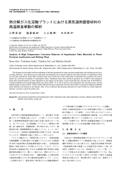
AP!‘il 17, 1956
G. A. ALLWARD
2,742,289
GAME RACKET CONSTRUCTION
Filed Dec. 9, 1953
IN VEN TOR
6604,66 A luwweo,
ATTORNEY5
-United States Patent G_ ICC
2,742,289
Patented Apr. 17,’ 1956
1
2
radii approximately equal to half the overall‘width of the’
web‘. As also shown in Fig. ‘13, in the preferred embodi
ment the arcs are swung about the median line of the flat
side of the web ‘as a center, and the channel has its neu- ,
2,742,289
tral plane 12-42 approximately at the level of the inside
GAME RACKET CONSTRUCTION
7
-
bottom of the groove.
’
. ,Still referring to the standard size badminton racket
George A. Allward, Lacombe, La.
example, the central 271/2 inches of the fouraand-one
half foot channel‘has adhesive'ly secured therein a liner
strip‘ 13, preferably of soft leather about 1/10 of an inch
thickfand the central 261/2 inches of the so lined chan
Application December 9, 1953, Serial No. 397,693‘
11 Claims. 2 (Cl. 273-43)
nel is'then perforated'through thechannel web and strip
with holes P1 etc., properly spaced to provide'for string
ing of the racket. In the embodiment shown 68 stringing
perforations are employed, the holes P1: and P68 being
This invention relates to game racket structures and
aims to provide an improved racket frame construction,
particularly but not exclusively a light, strong, resilient,
placed approximately ‘centrally of the throat bends, as .
shown in Fig. l, which throat bendsare effected with
warp-proof badminton racket. '
an external radius of about 1%; inch, as hereinafter more
The invention resides in the‘ novel features of con
fully described. Each of the perforations P1—-P68, at
its
inner end viewed in Fig. 1 is countersunk slightly,
pointed out in the appended claims.
the countersink in the case of drilled perforation P17 be
In the accompanying drawings of an illustrative em
ing indicated at 17a in Fig. 3. Still referringto the illus~
bodiment of the invention
trative embodiment of a standard badminton racket, the
Fig. l is a front elevation of a racket according to the
perforations P34 and P35 at the tip of the racket head
‘invention.
25
are spaced about 3116 inch respectively from the center
‘ Fig. 2 is a side elevation thereof.
line of the racket, and the curvature at the throat'bends
Fig. 3 is a cross section through the head of the frame
P1—-P68 also spaces the holes P1 and P68 about % inch ,
taken on the line 3--3, Fig. 1, looking in the direction
apart. Thus' the spacing of the holes in each quadrant
of the arrows.
Fig. 4 is a cross section through the shaft of the racket 30 of the racket may be a duplicate of that in each other
quadrant when a symmetrical head is employed, as in a
frame taken on the line 4-4, Fig. 1, looking .in the direc
struction hereinafter described and as more particularly
tion of the arrows.
. standard badminton racket, that in the illustrative em
.
Figs. 5', 6 and 7 are diagrams illustrative of the pre
ferred method of manufacture.
bodiment having seventeen holes to a quadrant prefer
7 Figs. 8, 9 and 10 are a longitudinal cross section,‘ a plan
view'and a transverse cross section of a modi?ed con
P1—P3, etc. up to P1—~P17, with P17 spaced about %
of an inch from P18: % inch, 1% plus, 1%3, 15/2, 2%g,
ably being as follows, measuring the distances P1—-P2,
struction of the’ channel, lining arrangement.
21%2! 3’
325/52: 4%2, 4%6: 42%2, 5%:
minus;
531/32, 6%,.
_
.
'_
i
Referring to Figs. 1-4, the racket frame of the pres
ent invention islformed from a single, continuous, solid,
As will be observed from the foregoing dimensions,
extruded channel 10 of light metal, preferably aluminum 4-0 the soft liner strip extends approximately a half inch be
or an aluminum alloy. For a standard sized badminton
yond the ends of the row of stringing holes, P1. to P68
, . racket the extruded channel or bar 10 may have a length
in the illustrative embodiment, and thus extends inside
the channel around the throat bends when the frameis
of about 41/2 feet. This channel, in accordance with this
invention has a special cross section, best shown in Figs.
3 and 4. In this cross section the neutral plane of bend ~15
As will be apparent from Fig. 2, the frame 'is also,
ing lies substantially at the level of the inner bottom 11
provided, when shaped, with a plurality of rivets R1—--R5v
of'the channel groove, as indicated by thepcenter lines
set into the reentrant portions‘ of the handle forming,
12--12 in Figs. v3 and 4. Thus when the channel is bent,
parts of the channels. The channels, before bending,-are
as shown in Fig. 1, the region of the bottom wall 11 un
preferably formed with holes to receive, at least one of
dergoes substantially no elongation or foreshortening.
these
rivets, preferably holes forthe rivet R2, which may
As indicated in. Fig. 3, for the standard badminton racket,
lie about 21/2 inches from the ?rst and last stringing
the preferred dimensions of the channel strip are: ‘over
holes P1 and P68 respectively. The holes for the rivets
all width w about % inch, overall depth d about W16 inch,
R1 and R3 to R6 may be preformed or formed after the
width of channel or groove g about 14; inch, thickness
shaped.
of base web t about 1/16 inch, the ?anges I having straight
55
parallel inner walls and outer walls lying on the arc of
a circle of radius r except for slight rounding of the’ four
parallel external edges of the extruded strip. Similar
proportions, designed to present the inner surface of the
base web approximately at ‘the neutral plane and to pre
sent a smooth rounded exterior, may be employed on a
somewhat larger ‘scale-for tennis racket construction and , .
the like.
Summarizing these features of the cross sec
bending of the frame, as desired.
'
‘
'
'
The channel strip, having been supplied with the“ liner,
and the stringing perforations having been formed ‘and
countersunk, the frame blank is ready for bending. This
bending operation is facilitated by the particular cross
section of thechannel, and the sequence of bendingsteps
now to, be described is particularly advantageous.
\
Referring to Fig. 5, in~the ?rst step of bendingpth'e
lined straight frame blank has its handle forming end por
tions bent at right angles ‘over a curved surface of av ra
tion without reference to speci?c dimensions, it will be
seen that the flat web has two ?anges extending from it 65 dius of approximately one quarter inch, with the bends'
positioned relative to the 1st and last stringingopenings
in the same ‘direction, and'de?ning a rectangular groove
therewith of a width approximately one-third the overall
P1, P68, as above described, as illustrated in diagramma
tic form.
l
‘
V
,
' .
width of the channel, the two ?anges being rounded from
the base ofv the web to the open edgelof the rectangular
During this sharp bending a slight ?attening and inward
groove, Also, that in the preferredv embodiment the 70 flow of the tips of the flanges p‘ occurs in effect narrow- .
groove has ‘a depth‘a‘bout twice the thickness of the web
ing the mouth of the channel groove g and aiding in
adjacent to it, the ?anges being rounded on arcs having I preventing the ends of the liner 13 from curling out of
2,742,289
3
become detached.
'
nel extending along said member, the external surfaces
of said ?anges being curved, said member having an ap
proximately semi-circular cross-section except for said
channel and being solid within the con?nes of its surface,
said member having a pair of straight end portions with
‘
When the two end sections of the channel have been
bent at right angles ‘to the central section thereof, as in
dicated in Fig. 5 ,g' the central section is sprung backwardly
as in Fig. 6 either-‘with orwithout the aid of a mandrel
their webs contiguous and an outwardly bowed central
andthis springingi'is continued until the throat portions
portion the extremities of which extend outwardly from
and handle portions are brought into contact with each
other as shown in solid lines in Fig. 7.
and form sharp bends with the adjacent straight end
portions, said straight end portions forming a shaft hav
ing an approximately circular cross-sectional contour ex
The handle
members are then secured together in any suitable man
ner. ‘When this securement is effected by riveting, at
least two rivets, as R2 and R1, and preferably all of
rivets‘ R1-v-R5 are then inserted. Following the secure
cept for said channel.
2. The frame of claim 1, further including a plurality
of rivets passing through the contiguous webs of said
rnent. of the handle members together the frame is ?at
straight portions and securing the latter together.
tened to an oval shapeas shownrin dotted lines in Fig. 7
3. The frame of claim 1, further including a handle
grip surrounding and ?xed to the free extremities of said
' by pressure on the sides of the head in the regions hH-h.
.In general all stringing and rivet holes are pie-drilled or
punched, and for a standard badminton racket the ovaliz
ing is conducted‘ to produce an oval having 7%" by 93/4 ”
straight end portions.
4. The game racket frame of claim 1, wherein said
channel is a rectangular groove of a width approximately
one-third the overall width of the channel member and
of a depth approximately twice the thickness of the web
outsidedimcnsions as illustrated in Fig. 1, i. 'e. a major
to minor axis ratio of about 39 to 31.
Due to the special shape of the channel member the
bending of the extruded section does not materially alter
the linear dimensions of the bottom face 11 of the groove
g or tend to stretch the liner out of hole-to-hole align
of said ‘member.
channel member has its neutral plane for bending ap
proximately at the level of the inside bottom of the groove.
6. A game racket frame comprising a single channel
member having a ?at web and a pair of ?anges extending
advantage stringing of the formed racket is facilitated
and separation of the liner from the channel member is
from one side of said web and forming therewith a chan
Furthermore, as the liner turns the corners at
nel extending along said member, the external surfaces
of said ?anges being curved, said member having an ap
proximately serni-circular cross-section except for said
channel, said member having a pair of straight end por
tions with their webs contiguous and an outwardly bowed
central portion, the extremities of which extend outwardly
from and form sharp bends with the adjacent straight
end portions, said bowed portion being provided with a
plurality of stringing holes through the web of said mem
the sharp throat bends under compression, and is seated
in the channel at an area where its ?anges are bent in
wardly somewhat over the'liuer, all tendency of the liner
to loosen and creep during the forming of the racket head
is
avoided.
'
,
Following the springing of the head into theshape
shown in solid lines in Fig. 7 the handle member 15 is
slipped over the ends of the shaft portions and secured
thereto, as by one or more rivets R6 passing therethrough
in the form shown. Thehole to receive the rivet R6 is
ber, the ?rst and last of said holes being located at said
bends, respectively, a handle grip surrounding‘ and a?ixed
to the free extremities of said straight end portions, and
preferably drilled clear through the handle 15 and the
facing channel members after the latter have been driven
tightly‘ into the handle 15.
>
5. The game racket frame of claim 4, wherein said
ment with the perforations P1-—P68, and because of this
avoided.
4
from one side of said web and forming therewith a chan
the’ “groove if their adhesive securement should ultimately
a liner of soft material secured in said channel around
.
said bowed portion and having openings therethrough
' In the form of Figs. l-4, above described, the stringing
holes are pro-drilled or punched and countersunk, and a
aligned with said ‘stringing holes, the tips of the ?anges
at said sharp bends being deformed inwardly to narrow
the mouth of the channel thereat, said liner extending
past said bends.
7. The frame of claim 1, said bends being contiguous
liner preferably of leather is used, to protect against
string-cutting. In the modi?ed form of Figs. 8—10, the
leather strip 13 (Figs. 2 and 3) is replaced by a molded
plastic strip'a13 having stringing sleeves 4b13 integral
and having a radius of curvature of the same order of
magnitude as the radius of curvature of said ?anges and
therewith and disposed to provide the proper string spac
ing for the shape of the racket head as above exempli?ed
in connection with the stringing holes P1—-P68. The
frame all] is provided with enlarged stringing sleeve re
ceiving perforations or holes a1’, preferably formed by a
being curved much more sharply than said bowed portion.
8. In a game racket construction, a single continuous
channel member having a ?at web and a pair of ?anges
extending from one side of said web and forming therewith
gang punch, and the sleeves [113 preferably terminate
?ush with the inner surface of the frame alt), as shown.
a channel extending along said member, said member hav
an approximately semi-circular cross-sectional contour
By the liner molding and gang punching procedure, the ~~ ing
except
for said channel and being solid within the con
assembly of the parts is expedited, and the sleeve lining
?nes
of
its surface, said memberhaving a pair of straight
of the stringing apertures affords complete protection
end portions with their webs ?xed in contact with each
against string cutting. As before, the ends of the liner
other to form a shaft having an approximately circular
at and beyond the end holes (P1 and P68 in Fig. l) are 60 cross-sectional contour except for said channel, and hav
placed under compression by the throat bends and thus
ing an outwardly bowed central portion the extremities of
held against lifting.
which extend outwardly from and form sharp bends with
While there have been described herein what are at
the adjacent straight end portions, said bends being con
present considered preferred embodiments of the inven
tiguous and being curved much more sharply “than said
tion, it will be obvious to those skilled in the art that
bowed portion, and a handle grip ?xed to and surrounding
the free extremities of said straight end portions.
9. In the construction of claim 8, said bowed portion
being formed with a plurality of stringing holes, said
many modifications and changes may be made therein
without departing from the essence of the invention. It
is therefore to be understood that the exemplary embodi
ments are illustrative and not restrictive of the invention,
the scope of which is de?ned in the appended claims, and
that all modi?cations that come within the meaning and
range of equivalency of the claims are included therein.
straight end portions being held together by rivets through
the webs thereof, and said handle grip being ?xed to
said straight end portions by a rivet through said handle
grip and said webs. '
'
I claim:
I
~
1. A game. racket frame comprising a single channel
member having a ?at web and a pair of ?anges extending
75
‘
v
10. ‘In a game racket construction, asingle channel
member having a ?at web and a pair of ?anges extending
2,742,289
4
5 ‘
‘
from one side of said web and forming therewith a chan
nel extending along said‘member, the external surfaces of
said ?anges being curved, said member having an approxi
mately semicircular cross-section except for said chan
nel and being solid within the con?nes of its surface, said
member having a pair of straight end portions with their
webs contiguous and an outwardly bowed oval central
portion the extremities of which extend outwardly from
' and form sharp bends with the adjacent straight end por
tions, the radius of curvature of the bend-s being such that 10
the oval is substantially continuous, whereby the central
strings may be secured directly to the channel member at
v the bends.
11. In the construction of claim‘ 10, said bowed por
, tion .being provided with a plurality of stringing holes
through the web of said member, the ?rst and last of said
holes being located at said bends, respectively.
References Cited in the ?le of this patent
UNITED STATES PATENTS
1,452,803
1,588,139
1,621,746
1,637,583
1,921,616
1,937,787
Robinson _____________ _; Dec. 5, 1933
1,982,448
Nash ________ __‘_____ __ Nov. 27, 1934
252,480
522,222
122,823
Great Britain __________ __ June 3, 1926
Great Britain ________ __ June 12, 1940
Australia ____________ __ Nov. 28, 1946
Harris _______________ .. Apr. 24,
Penny -__' ___________ __ June 8,
Morten ______________ __ Mar. 22,
Norten _______________ __ Aug. 2,
1923
1926
1927
1927
Hall ____ __'_ __________ __ Aug. 8, 1933
FOREIGN PATENTS
© Copyright 2026 ExpyDoc