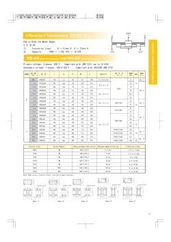
MTS・MHS
Hyper-miniature Slide Switches
RoHS Compliant
■ Specications
■Features
1. Extremely small and low-prole slide switch.
2. Available in a wide variety of circuits.
3. Surface mount type also available.
Rating
Max.
0.2A 12VDC
Min.
10mA 5VDC
Initial contact resistance 500Ω max.
Dielectric strength
500VAC 1 mnute
Insulation resistance
100MΩ min.
Electrical life
5,000 cycles
Operating
temperature range
Storage
temperature range
−10∼+70℃
−20∼+80℃
■Part Numbering
MHS 1 2 4
Code Mounting height on PC board
Fig.
Terminal styles
MTS
2 mm
1
PC terminal
MHS
3.5 mm
2
Right angle terminal
4
Surface mount type
Fig.
Numberof poles
1
1
2
2
2
2
4
4
3
3
Fig. Number of position
(Resistive load)
(Resistive load)
(1.5mA 200μVAC)
(500VDC)
MTS
MTS124
Non-shorting
Switching function
(Viewed from A)
ON
ON
3−2
3−1
Circuit diagram
No. of
terminals
3
●Operating force : 0.49∼2.45 N{50∼250 gf}
Surface Mount Pad Layout
(Top view)
SMT
Terminal numbers are not shown on the switch.
Details of K portion
☆MTS134
Non-shorting
Switching function
(Viewed from A)
Circuit diagram
ON
ON
ON
3−4
3−2
3−1
No. of
terminals
4
●Operating force : 0.735∼3.43 N{75∼350 gf}
Surface Mount Pad Layout
(Top view)
SMT
Terminal numbers are not shown on the switch.
Details of K portion
★:Made to order products.
☆:Semi-standard products.
MHS
MHS121
Non-shorting
Switching function
(Viewed from A)
Circuit diagram
No. of
terminals
(1)
ON
2−1
ON
3
(2)
(3)
2−3
●Operating force : 0.49∼3.92 N{50∼400 gf}
PC
■PC Hole Layouts
(Top view)
Terminal numbers are not shown on the switch.
MHS122
Non-shorting
Circuit diagram
0.3MAX
Switching function
(Viewed from A)
9.6
(1)
(3)
ON
3.5
(1)
No. of
terminals
2−3
ON
3
(2)
(3)
2−1
(2)
□1.5
R/A
●Operating force : 0.49∼3.92 N{50∼400 gf}
2 Stroke
3
3.5
(Top view)
2.5
■PC Hole Layouts
0.5
2.5
0.3
2.5
3.2
Terminal numbers are not shown on the switch.
MHS122 −1
Non-shorting
Switching function
(Viewed from A)
Circuit diagram
No. of
terminals
(1)
R/A
■PC Hole Layouts
(Top view)
Terminal numbers are not shown on the switch.
ON
ON
2−1
2−3
3
(2)
●Operating force : 0.49∼3.92 N{50∼400 gf}
(3)
MHS
MHS131
Non-shorting
Switching function
(Viewed from A)
Circuit diagram
No. of
terminals
(1)
ON
ON
3−1
PC
3−2
ON
(3)
(2)
4
(4)
3−4
●Operating force : 0.49∼3.92N{50∼400 gf}
■PC Hole Layouts
(Top view)
Terminal numbers are not shown on the switch.
★MHS132
Non-shorting
0.3MAX
Switching function
(Viewed from A)
12
(4)
0.3MAX
(2)
No. of
terminals
(1)
3.5
(1)
Circuit diagram
ON
(3)
3−4
ON
3−2
ON
(3)
(2)
4
(4)
3−1
1.5
R/A
2 Stroke
●Operating force : 0.49∼3.92 N{50∼400 gf}
2
■PC Hole Layouts
2.5
1.5
3.5
(Top view)
2.1
0.5
2
4
2
0.3
3.2
Terminal numbers are not shown on the switch.
MHS221
Non-shorting
Switching function
(Viewed from A)
Circuit diagram
No. of
terminals
(1)
(2)
ON
2−1
5−4
PC
(Top view)
Terminal numbers are not shown on the switch.
(3)
(4)
(5)
●Operating force : 0.49∼3.92 N{50∼400 gf}
■PC Hole Layouts
★:Made to order products.
ON
2−3
5−6
(6)
6
MHS
Non-shorting
Switching function
(Viewed from A)
0.3MAX
MHS222
9.6
(2)
(4)
(5)
No. of
terminals
(1)
(2)
(3)
ON
2−3
5−6
3.5
(1)
Circuit diagram
(6)
ON
2−1
5−4
(3)
(4)
(5)
6
(6)
□1.5
2 Stroke
R/A
●Operating force : 0.49∼3.92 N{50∼400 gf}
2.5
3.5
■PC Hole Layouts
3
(Top view)
0.5
0.3
2.5
3.2
2.5
Terminal numbers are not shown on the switch.
MHS231
Non-shorting
Switching function
(Viewed from A)
Circuit diagram
No. of
terminals
12
5.5
3.5
ON
3−1
7−5
ON
3−2
7−6
ON
3−4
7−8
8
●Operating force : 0.49∼3.92 N{50∼400 gf}
PC
Stroke
2
■PC Hole Layouts
2
1.5
2
1.5
3.5
(Top view)
3
0.5
2
4
0.3
3.3
2
Terminal numbers are not shown on the switch.
Non-shorting
Switching function
(Viewed from A)
12
(1)
(2)
(3)
(4)
(5)
(6)
(7)
(8)
ON
3−4
7−8
3.5
R/A
Circuit diagram
No. of
terminals
0.3MAX
★MHS232
ON
3−2
7−6
ON
3−1
7−5
8
1.5
2 Stroke
●Operating force : 0.49∼3.92 N{50∼400 gf}
(Top view)
2.5
3.5
■PC Hole Layouts
1.5
2
2.1
0.5
2
4
2
0.3
3.2
Terminal numbers are not shown on the switch.
★:Made to order products.
MHS
MHS422
Non-shorting
Switching function
(Viewed from A)
R/A
■PC Hole Layouts
ON
ON
2−3
5−6
8−9
11−12
2−1
5−4
8−7
11−10
Circuit diagram
No. of
terminals
12
●/Operating force : 1.47∼3.92N{150∼400 gf}
(Top view)
Terminal numbers are not shown on the switch.
0.7
■Flux Cleaning
⑴Manual Soldering(MTS/MHS Series)
Device : Soldering iron
① 380℃, Max.; 3 seconds, Max.
⑵Auto Soldering(MHS121/MSH131/MHS221/MHS231 only)
Device : Jet wave type or dip type
① 275℃, Max.; 6 seconds, Max.
●Pre-heating should be done at temperatures ranging from 80℃
to 120℃ and within 120 seconds
⑶Reow soldering
(MTS Series)
Device : Heat-blow or infrared
⑴Solvent : Fluorine or Alcohol type.
⑵Since the MTS-MHS series are not process sealed, if the PC
board is to be cleaned, clean the soldering surface of substrate
with a brush so that the switch is not exposed to the cleaning
solution.
Temperature
■Soldering Specications
●Apply reow soldering only once.
⑷When soldering two or more terminals to the common land,
use solder resist to solder them independently.
■Frequency of switch use
If the switch is not likely to be operated frequently (e.g.
two or three operations a year) in the dry circuit area, a
sulfide film is likely to be formed on the contacts, resulting
in contact failure. If this is the case, gold-plated products
are recommended. Please contact your local Nidec Copal
Electronics sales representative.
■Packaging Specications
Plastic Bag
200 pcs/pack
© Copyright 2026 ExpyDoc