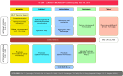
Feasibility study of Air Traffic Control Towers around the globe Appendix report Delft University of Technolog J. H. Hartmann Cover: This photo has been taken at Amsterdam Schiphol Airport. In the back (left) the main air traffic control tower with a height of 100 meter is shown and the secondary tower (right) is the old control tower and operates at this moment as air traffic controller training facility. The main tower is constructed by Bureau De Weger in cooperation with architect Netherlands Airports Consultants (NACO) in 1991. In front an Airbus A320-200 of Swiss International Air Lines is taxiing and ready for departure. [www.airchive.com] Appendix report “Feasibility study of air traffic control towers around the globe” “International research regarding the local influences providing an optimal structural design for air traffic control towers around the globe in an economical perspective” J.H. Hartmann Department of Building Engineering Faculty of Civil Engineering and Geosciences Delft University of Technology 2628GN/2600GA Delft The Netherlands www.tudelft.nl August, 2014 © Copyright 2014 Joost Hartmann Delft University of Technology, Delft, the Netherlands All rights reserved. No part of this document may be reproduced for commercial purposes without written consent from the author. Permission is granted to reproduce for personal and educational use only with the use of proper citation. Commercial copying, hiring, lending and selling are prohibited without written consent from the author. For inquiries regarding this thesis research please contact the author via e-mail: [email protected] MSc Thesis research report FEASIBILITY STUDY OF AIR TRAFFIC CONTROL TOWERS AROUND THE GLOBE Preface This appendix report contains all the additional information of the research report of the master thesis research “Feasibility study of air traffic control towers around the globe”. This document acts as a foundation of the research report, but due to its size this document is not added and should be used as a reference document. This report contains, besides comprehensive structural tower calculations and designs, spreadsheets of the wind and earthquake load determination, an extensively country determination, a current ATC tower analysis and a system engineering approach. The Hague, August 2014 Joost Hartmann 5 | Royal HaskoningDHV – TU Delft – Joost Hartmann FEASIBILITY STUDY OF AIR TRAFFIC CONTROL TOWERS AROUND THE GLOBE MSc Thesis research report Keywords: air traffic control tower, airport control, IMF, current ATC tower figures, structural tower design, structural engineering, international construction industry, The Netherlands, Japan, China, Turkey, Indonesia, Nigeria, wind engineering, earthquake engineering, system engineering Royal HaskoningDHV – TU Delft – Joost Hartmann | 6 MSc Thesis research report FEASIBILITY STUDY OF AIR TRAFFIC CONTROL TOWERS AROUND THE GLOBE Table of Contents Appendix I Country determination ................................................................................................................. 9 I.I Introduction ........................................................................................................................................... 9 I.II Phase 1: Air traffic development ......................................................................................................... 10 I.III Phase 2: Geographical conditions........................................................................................................ 16 I.IV Phase 3: Offices Royal HaskoningDHV ................................................................................................. 18 I.V Conclusion ........................................................................................................................................... 19 I.VI Additional annexes .............................................................................................................................. 20 Appendix II Current ATC tower investigation ................................................................................................ 29 Appendix III Reference projects ...................................................................................................................... 31 III.I Schiphol Airport (I)............................................................................................................................... 31 III.II Schiphol Airport (II) .............................................................................................................................. 32 III.III Vienna Airport ..................................................................................................................................... 33 III.IV London Heathrow Airport ................................................................................................................... 34 III.V Istanbul Sabiha Gokcen Airport ........................................................................................................... 35 IIII.VI Ashgabat International Airport ............................................................................................................ 36 III.VII Taiwan Taoyuan International airport ................................................................................................. 37 III.VIII ATC tower collage ................................................................................................................................ 38 Appendix IV System engineering ..................................................................................................................... 39 IV.I Decomposition step 1: Main system ................................................................................................... 39 IV.II Decomposition step 2: Sub-systems .................................................................................................... 40 IV.III Decomposition step 3: Components ................................................................................................... 44 IV.IV Decomposition step 4: Elements ........................................................................................................ 54 Appendix V Sketch-up model Approach paths ............................................................................................... 65 Appendix VI Spreadsheets wind engineering ............................................................................................. 67 VI.I Wind calculation The Netherlands - Lelystad ...................................................................................... 67 VI.II Wind calculation Nigeria - Abuja ......................................................................................................... 67 VI.III Wind calculation Japan - Tokyo ........................................................................................................... 69 VI.IV Wind calculation China - Nanjing......................................................................................................... 70 VI.V Wind calculation Turkey - Istanbul ...................................................................................................... 71 VI.VI Wind calculation Indonesia - Jakarta ................................................................................................... 72 Appendix VII Spreadsheets earthquake engineering ................................................................................... 72 VII.I Earthquake calculation The Netherlands - Lelystad ............................................................................ 73 VII.II Earthquake calculation Nigeria - Abuja ............................................................................................... 74 VII.III Earthquake calculation Japan - Tokyo ................................................................................................. 75 VII.IV Earthquake calculation China – Nanjing .............................................................................................. 76 VII.V Earthquake calculation Turkey Istanbul .............................................................................................. 77 VII.VI Earthquake calculation Indonesia - Jakarta ......................................................................................... 78 7 | Royal HaskoningDHV – TU Delft – Joost Hartmann FEASIBILITY STUDY OF AIR TRAFFIC CONTROL TOWERS AROUND THE GLOBE MSc Thesis research report Appendix VIII Synthesis concept designs ...................................................................................................... 79 VIII.I.I Lelystad airport – structural aspects ................................................................................................... 79 VIII.I.II Lelystad airport – labour aspects......................................................................................................... 80 VIII.I.III Lelystad airport – material aspects...................................................................................................... 81 VIII.II.I Abuja airport – structural aspects ...................................................................................................... 81 VIII.II.II Abuja airport – labour aspects ............................................................................................................ 83 VIII.II.II Abuja airport – labour aspects ............................................................................................................ 84 VIII.III.I Tokyo airport – structural aspects ...................................................................................................... 85 VIII.III.II Tokyo airport – labour aspects ........................................................................................................... 85 VIII.III.II Tokyo airport – material aspects ........................................................................................................ 87 VIII.IV.I China airport – structural aspects ...................................................................................................... 88 VIII.IV.II China airport – labour aspects........................................................................................................... 88 VIII.IV.III China airport – material aspects ....................................................................................................... 90 VIII.V.I Istanbul airport – structural aspects ................................................................................................... 91 VIII.V.II Istanbul airport – labour aspects ........................................................................................................ 92 VIII.V.III Istanbul airport – material aspects ..................................................................................................... 93 VIII.VI.I Jakarta airport – material aspects ..................................................................................................... 94 VIII.VI.II Jakarta airport – labour aspects ........................................................................................................ 95 VIII.VI.III Jakarta airport – material aspects ..................................................................................................... 96 Appendix IX Calculations concept designs .................................................................................................. 97 IX.I.I Lelystad airport – Concrete core in-situ ............................................................................................. 97 IX.I.II Lelystad airport – Concrete core prefab ........................................................................................... 101 IX.II.I Abuja airport – Tapered concrete core ............................................................................................. 105 IX.III.I Tokyo airport – Eccentric steel braced frame .................................................................................... 109 IX.III.II Tokyo airport – Concrete core in-situ ................................................................................................ 114 IX.III.III Tokyo airport – Concentric steel braced frame ................................................................................. 119 IX.IV.I Nanjing airport – Concrete core in-situ ............................................................................................. 124 IX.IV.II Nanjing airport – Tapered concrete core .......................................................................................... 129 IX.IV.III Nanjing airport – Eccentric steel braced frame ................................................................................. 134 IX.V.I Istanbul airport – Concrete core in-situ ............................................................................................. 139 IX.V.II Istanbul airport – Concentric steel braced frame .............................................................................. 144 IX.VIII.I Jakarta airport – Tapered concrete core in-situ ................................................................................ 149 IX.III.II Jakarta airport – Eccentric steel braced frame .................................................................................. 154 IX.VIII.III Jakarta airport – Concrete core in-situ ............................................................................................. 159 List of figures ....................................................................................................................................................... 165 List of tables ........................................................................................................................................................ 166 Royal HaskoningDHV – TU Delft – Joost Hartmann | 8 MSc Thesis research report Appendix I FEASIBILITY STUDY OF AIR TRAFFIC CONTROL TOWERS AROUND THE GLOBE Country determination I.I Introduction This thesis research is focussing on the local geographical, weather, social and building conditions around the globe. Around the globe 195 different countries exist. These countries are shown in figure I.I, the well-known world. In order to get reliable and sufficient information as input for the framework and on the other hand reduce research time, first an investigation has been performed in order to select a handful of countries that will cover the research scope. Figure I.I: Countries around the globe [images-google, 2013] To decrease the total amount to a handful of countries three steps are defined. In the first step the global air traffic development will be analysed. Statistics of welfare and population growth per country will be used and other aspects will be taken into account to predict the highest demand of air traffic per country in the nearby future. After this step the majority of countries will be disregarded. The second step is orientated on the local geographical and weather conditions of the already chosen countries and the last phase is taking into account the international offices of Royal HaskoningDHV. Input: 195 countries 1. Air Traffic Development - Welfare per country - Population growth per country - Orders aircraft manufactures - Global sport events 2. Geographical - Wind & Hurricanes - Earthquakes 3. Offices Output: 6 countries The entire process is given in figure I.II. Figure I.II: Country determination process 9 | Royal HaskoningDHV – TU Delft – Joost Hartmann MSc Thesis research report FEASIBILITY STUDY OF AIR TRAFFIC CONTROL TOWERS AROUND THE GLOBE I.II Phase 1: Air traffic development I.II.I Welfare per country One of the aspects is the influence of welfare of the chosen countries. Welfare is described as the economic and social development of a country which can be expressed in terms of individuals and the society as a whole. The Gross Domestic Product (GDP) is an indicator of the economic welfare and on basis of these values economic growth can be predicted. The GDP reflects the economic situation of the whole country and to be able to make comparisons between different countries the GDP has to be expressed in current U.S. dollars per person. These data are given by the International Monetary Fund, [IMF, 2013]. More extended files are presented in section I.VI.I. Table I.I: Top 10 Gross Domestic Product growth in millions per country [IMF, 2013] Country Units GDP 2018 $ [in million] USA China Japan Russia Germany UK India France Brazil Korea U.S. dollars U.S. dollars U.S. dollars U.S. dollars U.S. dollars U.S. dollars U.S. dollars U.S. dollars U.S. dollars U.S. dollars 21.556.047 13.760.435 5.943.390 3.010.421 4.360.590 3.244.944 2.481.175 3.422.404 2.730.232 1.702.115 Growth GDP $ [in million] Growth in [%] 4.831.775 4.821.108 936.187 892.590 767.352 755.270 722.959 683.728 540.014 504.609 Average growth per year [%] 28,89 53,93 18,70 42,15 21,36 30,34 41,12 24,97 24,66 42,14 4,82 8,99 3,12 7,02 3,56 5,06 6,85 4,16 4,11 7,02 Table I.I gives an overview of the top 10 countries with the highest GDP growth in millions for the upcoming 5 years. Like expected the largest economies of the world are presented in this table, but keep in mind that these countries don’t has to be necessarily the richest countries. This can be explained with the comparison between table I.I and table I.II. Table I.II represents the GDP growth in dollars per person per country. This data is derived by first converting GDP in national currency to U.S. dollars and then dividing it by the total population. The main reason of the difference between the two tables is the total amount of people per country. Table I.I represents countries with a high amount of inhabitants and the opposite counts for table I.II. Note that the United States is the only country listed in both tables. Table I.II: Top 10 Gross Domestic Product growth in dollars per person [IMF, 2013] Country Units Luxembourg Qatar Norway Switzerland Sweden Denmark Australia USA Canada Austria U.S. dollars U.S. dollars U.S. dollars U.S. dollars U.S. dollars U.S. dollars U.S. dollars U.S. dollars U.S. dollars U.S. dollars GDP 2018 $ 135360,9 114935,3 113412,8 91240,95 72564,76 69448,8 68956,7 65125,99 61764,2 60637,29 Growth GDP $ 24787,888 10280,084 12141,399 10965,171 15267,479 11450,132 4799,784 12286,826 9892,989 11381,684 Growth in [%] 17,15 8,80 10,83 9,97 21,76 15,26 10,99 19,26 16,28 17,42 Average growth per year [%] 2,86 1,47 1,80 1,66 3,63 2,54 1,83 3,21 2,71 2,90 Royal HaskoningDHV – TU Delft – Joost Hartmann | 10 MSc Thesis research report FEASIBILITY STUDY OF AIR TRAFFIC CONTROL TOWERS AROUND THE GLOBE The air traffic control tower does not fall under the legislations of the associated airport [ICAO]. The responsibilities of these towers are allocated to the ministry of transport, or in case of The Netherlands to Rijkswaterstaat. Each ministry has got his own organization to operate the towers. The air traffic control towers can therefore be seen as public utility buildings. The design and construction of these buildings are funded by the client; in this case the local governments. With this prospect the gross domestic growth of a country will be taken as normative, because countries with a high GDP are able to invest more in public services. With this in mind, it is interesting to gain more information about the GDP per country; next step is to investigate the growth rate of the GDP per country. This rate gives information about countries that are developing (relatively) fast. In table I.III the top 10 fastest growing countries in % are presented. It can be concluded that these are all developing countries (third world countries), because their total GDP 2018 in millions is very low compared with the countries from table I.I. Table I.III: Top 10 Gross Domestic Product Growth in % per country [IMF, 2013] Country Units Scale São Tomé and Príncipe Libya Turkmenistan Bhutan Guinea Kazakhstan Eritrea Liberia Mozambique Azerbaijan U.S. dollars U.S. dollars U.S. dollars U.S. dollars U.S. dollars U.S. dollars U.S. dollars U.S. dollars U.S. dollars U.S. dollars Billions Billions Billions Billions Billions Billions Billions Billions Billions Billions GDP 2018 $ [in million] 878 147.075 81.756 3.887 11.773 397.063 6.036 3.429 25.040 129.633 Growth GDP $ [in million] Growth in [%] Average growth per year [%] 182,32 107,37 101,57 82,23 79,91 76,58 75,57 73,44 70,70 70,55 30,39 17,89 16,93 13,71 13,32 12,76 12,59 12,24 11,78 11,76 567 76.151 41.196 1.754 5.229 172.205 2.598 1.452 10.371 53.624 I.II.II Population growth per country In this section the population growth per country will be analysed. Like already noticed in section I.II.I there is a relation between a nation’s welfare and its population. Beside this economical point of view, the more important aspect of a growing population of a nation is the coherent growth of air traffic demand. The International Monetary Fund also registers the population growth. The top 10 of growing countries in absolute value (annually) of the world are presented in table I.IV; more extended files are presented in section I.VI.II. Table I.IV: Top 10 Population growth per county in absolute value [IMF, 2013] Country Units Scale India China Nigeria Pakistan Indonesia USA Congo Ethiopia Philippines Egypt Persons Persons Persons Persons Persons Persons Persons Persons Persons Persons Millions Millions Millions Millions Millions Millions Millions Millions Millions Millions 11 Population in 2018 [x 1000] 1.327.304 1.394.883 193.875 201.261 266.146 330.990 89.254 99.063 107.631 93.821 Growth people [x 1000] | Royal HaskoningDHV – TU Delft – Joost Hartmann 13.995 5.687 4.099 3.112 3.032 2.413 2.044 1.702 1.691 1.612 FEASIBILITY STUDY OF AIR TRAFFIC CONTROL TOWERS AROUND THE GLOBE MSc Thesis research report Table I.V: Top 10 Population growth per country in relative percentage [IMF, 2013] Country Units Scale Qatar Zambia Uganda Eritrea Mali Niger Oman Iraq Congo Tanzania Persons Persons Persons Persons Persons Persons Persons Persons Persons Persons Millions Millions Millions Millions Millions Millions Millions Millions Millions Millions Population in 2018 [x1000] 2.324 17.111 43.315 7.442 19.647 19.339 3.708 40.348 89.254 53.647 Growth people [x 1000] Relative [%] 69 429 1.082 186 466 456 87 929 2.044 1.228 2,97 2,51 2,50 2,49 2,37 2,36 2,35 2,30 2,29 2,29 Next to the absolute value, it is also interesting to investigate the top 10 countries with the highest relative percentage growth (annually). In table I.V these values are present. It is noticed that 7 countries are African and the other 3 are located in the Middle East. An explanation for this geographical distribution could be the characteristics of a developing country. In this case Qatar and Oman can be seen as an exception due to the good economic welfare of these countries, therefore the large growth is explained caused by the expatriates. In this research the absolute value of the population growth (table I.IV) is taken as normative. The growth values of people per year are much higher and therefore more interesting in air traffic demand prospective. I.II.III Conclusion Internal Monetary Fund On basis of an objective methodology, conclusions will be made to predict the countries with the highest air traffic demand in the future. To relate the Internal Monetary Fund figures to the potential air traffic growth per country, three main parameters will be valued, compared and are explained below to assign their mutually importance: Parameter 1 – GDP growth in millions per country – Factor value 1.0 As stated in section I.II.I air traffic control towers are seen as public utility buildings and are funded by governments. Therefore the influence of the GDP growth in millions per country is a known parameter and has to be valued to be able making comparisons with the other parameters. However the level of importance cannot be determined but the value can perform as a reference value. To make an objective approach this value will be stated on 1.0, whereby the multiplied outcome will not be changed and is exact as the input value. Next step is to investigate the other parameters and give them values related to the reference value of 1.0. The value difference is stated on + and - 0.25 in order to justify the unknown importance differences. Parameter 2 – GDP Growth in % per country – Factor value 0.75 As already mentioned the GDP growth per country is an important value. When referring to table I.III it can be seen that countries, with a high GDP growth in %, are mainly third world countries with a low total GDP. In general the air traffic demand will be lower in these kinds of countries. Therefore the factor value of parameter 2 can be predicted to be lower than as the reference value and is valued 0.75. Royal HaskoningDHV – TU Delft – Joost Hartmann | 12 MSc Thesis research report FEASIBILITY STUDY OF AIR TRAFFIC CONTROL TOWERS AROUND THE GLOBE Parameter 3 – Population growth per county in absolute value – Factor value 1.25 When the population of a country growths; the air traffic demand in that country can be expected to become higher as well. Therefor the factor value of parameter 3 can be predicted to be higher than as the reference value and valued 1.25. The expectation is explained with a small calculation below: Take the demand to fly, expressed per person percentage, is constant during the next 5 years with a value of 10 %. E.g. A country with 100.00 inhabitants, (100.000 x 0.1 =) 10.000 persons wants to fly. Next take that the country’s population expand (reference to table I.III) this results in a netto increase of e.g. 100.000 to 110.000 inhabitants. The total amount of people that want to fly will become 110.000 x 0.1 = 11.000 persons. To make this comprehensive comparison, the top 50 countries of each parameter are listed together in one main table. This table is shown on the next page in table I.VII. Next all the parameters are multiplied with their weight factors. After the calculation a summary of the top 30 is made and presented in table I.VI. China is the best scoring country with a total score of 135. On basis of this table the reduction of countries will continue. Table I.VI: Country Index 1 Top 30 Parameter 1 China India US Turkey Indonesia Egypt Brazil Bangladesh Philippines Nigeria Mexico Vietnam Russia Kazakhstan Myanmar Kenya Iraq UK Pakistan Congo Saudi Arabia Ethiopia Tanzania Japan Côte d'Ivoire Germany South Africa Uganda Colombia France 13 49 44 50 40 36 25 42 10 26 24 37 13 47 30 0 0 19 45 0 0 27 0 0 48 0 46 17 0 21 43 Factor 1 1 1 1 1 1 1 1 1 1 1 1 1 1 1 1 1 1 1 1 1 1 1 1 1 1 1 1 1 1 1 Parameter 2 Factor 0,75 33 22 0 43 8 24 0 37 11 0 0 29 30 46 27 21 0 0 0 0 0 0 0 0 20 0 0 0 0 0 | Royal HaskoningDHV – TU Delft – Joost Hartmann 0,75 0,75 0,75 0,75 0,75 0,75 0,75 0,75 0,75 0,75 0,75 0,75 0,75 0,75 0,75 0,75 0,75 0,75 0,75 0,75 0,75 0,75 0,75 0,75 0,75 0,75 0,75 0,75 0,75 0,75 Parameter 3 49 50 45 27 46 41 38 40 42 48 34 30 0 2 37 36 33 12 47 44 22 43 39 0 26 0 23 35 18 0 Factor 1,25 1,25 1,25 1,25 1,25 1,25 1,25 1,25 1,25 1,25 1,25 1,25 1,25 1,25 1,25 1,25 1,25 1,25 1,25 1,25 1,25 1,25 1,25 1,25 1,25 1,25 1,25 1,25 1,25 1,25 1,25 Total score 135 123 106,25 106 99,5 94,25 89,5 87,75 86,75 84 79,5 72,25 69,5 67 66,5 60,75 60,25 60 58,75 55 54,5 53,75 48,75 48 47,5 46 45,75 43,75 43,5 43 FEASIBILITY STUDY OF AIR TRAFFIC CONTROL TOWERS AROUND THE GLOBE MSc Thesis research report Table I.VII: Country index 2 Parameter 1 GDP growth [million] 50 49 48 47 46 45 44 43 42 41 40 39 38 37 36 35 34 33 32 31 30 29 28 27 26 25 24 23 22 21 20 19 18 17 16 15 14 13 12 11 10 9 8 7 6 5 4 3 2 1 Country United States China Japan Russia Germany UK India France Brazil Korea Turkey Canada Italy Mexico Indonesia Spain Australia Taiwan Sweden Poland Kazakhstan Netherlands Thailand Saudi Arabia Philippines Egypt Nigeria Hong Kong SAR Malaysia Colombia Chile Iraq Switzerland South Africa Austria Belgium Argentina Vietnam Peru Norway Bangladesh Israel United Arab Emirates Finland Libya Denmark Qatar Greece Ukraine Ireland Parameter 2 GDP growth [%] 50 49 48 47 46 45 44 43 42 41 40 39 38 37 36 35 34 33 32 31 30 29 28 27 26 25 24 23 22 21 20 19 18 17 16 15 14 13 12 11 10 9 8 7 6 5 4 3 2 1 Country São Tomé and Príncipe Bhutan Turkmenistan Guinea Kazakhstan Libya Mozambique Turkey Azerbaijan Liberia Georgia Cambodia Zimbabwe Bangladesh Moldova Lao P.D.R. Lithuania China Mauritania Sri Lanka Russia Vietnam Eritrea Myanmar Belarus Panama Egypt Maldives India Kenya Côte d'Ivoire Rwanda Suriname Latvia FYR Macedonia Papua New Guinea Estonia Hong Kong SAR Burkina Faso Philippines Mauritius Taiwan Indonesia Armenia Haiti Ukraine Lesotho Korea Cape Verde Madagascar Parameter 3 Population growth 50 49 48 47 46 45 44 43 42 41 40 39 38 37 36 35 34 33 32 31 30 29 28 27 26 25 24 23 22 21 20 19 18 17 16 15 14 13 12 11 10 9 8 7 6 5 4 3 2 1 Country India China Nigeria Pakistan Indonesia United States Congo Ethiopia Philippines Egypt Bangladesh Tanzania Brazil Myanmar Kenya Uganda Mexico Iraq Afghanistan Iran Vietnam Sudan Yemen Turkey Côte d'Ivoire Ghana Angola South Africa Saudi Arabia Algeria Cameroon Madagascar Colombia Mali Niger Malaysia Malawi Zambia UK Peru Venezuela Argentina Mozambique Nepal Burkina Faso Guatemala Senegal Uzbekistan Kazakhstan Canada Royal HaskoningDHV – TU Delft – Joost Hartmann | 14 MSc Thesis research report FEASIBILITY STUDY OF AIR TRAFFIC CONTROL TOWERS AROUND THE GLOBE I.II.IV Orders aircraft manufactures In the world there are two major aircraft manufactures; Boeing and Airbus. Despite the economic crisis still a lot of aircrafts are being ordered and built. In this section the orders of both manufactures are analysed and gives an indication of the air traffic development per country. The orders are divided in continents and only the orders higher than 50 aircrafts per airline are considered. All the orders of the French Airbus and American Boeing aircraft are presented in section I.VII. Table I.VIII gives a total overview of ordered aircrafts per country. It can be seen that the largest orders are in the USA and the Asia-Pacific region. The least aircrafts are ordered in the African region. When a comparison is made between table I.IV and table I.VIII, a high number of countries correspond. With this as a given it can be concluded that the GDP index and people growth are in relation with the ordered aircrafts and furthermore the air traffic development per country. Table I.VIII: Total ordered aircrafts [Hartmann, J., 2013] List of countries Total amount of ordered aircrafts USA Indonesia India Malaysia Turkey Norway UK Germany Ireland Dubai Singapore Brazil Qatar Australia Hong Kong Hungary Chili Philippines China Libya South Africa 2081 512 393 350 282 237 209 175 175 173 169 160 141 132 78 70 67 60 45 13 8 I.II.V Global sport events During the last decades, increasing competitions between countries arise to host large sport events. Due to this fierce competition, hosting countries promise the organizing committee to have the best facilities, also regarding in the local infrastructure. Often airports are refurbished or extended; therefor it is also interesting to investigate the future locations of these global events. In section I.VIII a total overview for the upcoming sport events is presented. The already known locations and therefore useful countries are: Olympic summer games 2016 – Brazil, Rio de Janeiro Olympic summer games 2020 – Japan, Tokio Olympic winter games 2018 – South Korea, Pyeongchang Asian games 2017 – Turkmenistan, Ashgabat Asian games 2019 – Vietnam, Hanoi World cup Football 2018 - Russia World cup football 2022 - Qatar 15 | Royal HaskoningDHV – TU Delft – Joost Hartmann FEASIBILITY STUDY OF AIR TRAFFIC CONTROL TOWERS AROUND THE GLOBE I.III MSc Thesis research report Phase 2: Geographical conditions In the process of making a structural design of an air traffic control tower located around the globe, it is important to take the two most important geographical and weather conditions into account. These conditions are wind/hurricane and earthquake actions and in this section the topographic of these phenomena are discussed. I.III.I Wind & Hurricanes This phenomenon is caused by air that flows from areas with high air pressures to areas with low air pressures. The closer these two areas are together, the higher the pressure difference and the stronger the winds. The wind speed is not only depending on its location but also to the height. Due to friction the wind speed is in general lower near the earth surface. More information about wind and hurricanes is given in chapter 3 “wind engineering” in the literature report. Everywhere around the world wind occurs, but at some areas this wind can get higher magnitudes and are classified as hurricanes, cyclones and tropical storms. These storms are formed over warm oceans in the summer and early fall and are intense low pressure areas that gets his energy by evaporation of warm water from the ocean surface. The paths of these storms are presented in figure I.III. Figure I.III: Hurricane paths around the world past 170 years [web, www.wired.com] This figure shows that the hurricane areas are well bounded and it can be seen that the Philippines is located in th the middle of the marked area which caused the big disaster on the 8 of November 2013. This hurricane is the heaviest storm that hit land with an average wind speed of 315 km/h and wind gusts of 380 km/h [www.ad.nl, 2013]. From figure I.III a quick country/area list is made and presented below to order hurricane affected countries: USA Central America Caribbean Indonesia Japan Philippines Madagascar India Mozambique China & Taiwan Vietnam Australia Royal HaskoningDHV – TU Delft – Joost Hartmann | 16 MSc Thesis research report I.III.II FEASIBILITY STUDY OF AIR TRAFFIC CONTROL TOWERS AROUND THE GLOBE Earthquakes The second phenomenon is earthquake action. The thickness of the earth’s crust is perilously thin, compared with the radius of the earth, and is floating on molten rock. Powered by vast amounts of thermal energy, large forces are generated that are able to move the earth tectonic plates. In some places, tectonic plates slip horizontally along each other, where at other places the plates are pushing against each other, where the thinner plate bends and slides under. Due to the roughness at the edges of the plates, sliding is restrained. The rock at the edges absorbs compression and shear strains until it suddenly ruptures. All the accumulated energy releases in a sudden violent movement and an earthquake is born. More information about earthquakes is given in chapter 4 “Earthquake engineering” in the literature report. Figure I.IV: Global seismic hazard map [www.seismo.ethz.ch/static/gshap/] Over the globe there are 7 primary tectonic plates and the global seismic hazard is given in figure I.IV. From figure I.IV a quick country/area list is made and presented below to order earthquake affected countries. 17 USA Central America Caribbean Chili Peru Colombia Ecuador Venezuela Romania Greece Italy Turkey Iran Turkmenistan | Royal HaskoningDHV – TU Delft – Joost Hartmann Russia India Indonesia Japan China Philippines New Zealand FEASIBILITY STUDY OF AIR TRAFFIC CONTROL TOWERS AROUND THE GLOBE I.IV MSc Thesis research report Phase 3: Offices Royal HaskoningDHV To get reliable and sufficient information, the global offices of Royal HaskoningDHV are being taken into account in determine the countries. In figure I.V the global office configuration is given. Figure I.V: Offices RHDHV located around the globe [RoyalHaskoningDHV, 2013] From figure I.V a quick country list is made and presented below. Botswana Ghana Libya Mozambique Nigeria South Africa Zimbabwe Brazil Canada Trinidad and Tobago Australia Cambodia China India Indonesia Malaysia Singapore Thailand Vietnam Dubai Oman Saudi Arabia Qatar Israel Bahrain Turkey Russia Poland Czech Republic Belgium Royal HaskoningDHV – TU Delft – Joost Hartmann | 18 MSc Thesis research report I.V FEASIBILITY STUDY OF AIR TRAFFIC CONTROL TOWERS AROUND THE GLOBE Conclusion From all the previous investigations a short-list of twelve countries is made. These are the most interested countries to investigate regarding potential air traffic demand, extreme weather conditions and offices of RHDHV around the globe. Table I.IX: Short list Country Region Earthquakes Hurricanes Wealth in U.S Dollars Poor US Brazil Turkey Russia China India Vietnam Indonesia South Africa Mozambique Nigeria Japan The Americas The Americas Europe / Middle east Europe Asia Asia Asia Asia Africa Africa Africa Asia Yes No Yes No Yes No No Yes No No No Yes Yes No No No Yes Yes Yes Yes No Yes No Yes $ 65.125,00 $ 13.199,00 $ 15.888,00 $ 21.674,00 $ 9.864,00 $ 1.869,00 $ 2.843,00 $ 4.553,00 $ 8.459,00 $ 990,00 $ 443,00 $ 47.386,00 No Intermediate Intermediate Intermediate Intermediate Yes Yes Yes Intermediate Very Poor Very Poor No The Netherlands Europe No No $ 57.035,00 No The Netherlands is not presented in this list, but as a Dutch student and working for a Dutch company, the Netherlands will be definitely be included, also to be able to get more insight in the well-known Dutch and European building industry compared with the globe building industry. Table I.X: Chosen countries Country Special Wind Earthquake Wealth 1) Indonesia 2) Turkey Both Earthquake Yes No Yes Yes Poor Intermediate 3) Nigeria Poor No No Very poor 4) China Wind Yes Yes Intermediate 5) Japan Both Yes Yes Rich 6) Netherlands Rich No No Rich Next step is to select the last six countries. In order to get an overall satisfying result, every country is selected with one particular property. E.g. Rich countries like Japan and the Netherlands can be compared regarding their building vision on extreme weather conditions, or rich versus poor. Note that the wealth decision is determined on the GDP in dollars per person, this figure does not only (roughly) indicate the total wealth fare of the country, but also the single human’s wealth and this is also interesting regarding the societal environment of that specific country. 19 Figure I.VI: National Flags [images-google, 2013] | Royal HaskoningDHV – TU Delft – Joost Hartmann FEASIBILITY STUDY OF AIR TRAFFIC CONTROL TOWERS AROUND THE GLOBE I.VI Additional annexes I.VI.I GDP growth by IMF MSc Thesis research report In this annex the Gross Domestic Product (GDP) growth per country is given. Interesting values to investigate are the GDP growth in millions per country, GDP growth in dollars per person and the GDP growth in percentage per country. These growth figures are presented in tables I.XI, I.XII and I.XIII Table I.XI Top 25 GDP growth in millions per country [IMF, 2013] Royal HaskoningDHV – TU Delft – Joost Hartmann | 20 MSc Thesis research report FEASIBILITY STUDY OF AIR TRAFFIC CONTROL TOWERS AROUND THE GLOBE Table I.XII Top 25 GDP growth in dollar per person [IMF, 2013] 21 | Royal HaskoningDHV – TU Delft – Joost Hartmann FEASIBILITY STUDY OF AIR TRAFFIC CONTROL TOWERS AROUND THE GLOBE MSc Thesis research report Table I.XIII Top 25 GDP growth in percentage per country [IMF, 2013] Royal HaskoningDHV – TU Delft – Joost Hartmann | 22 MSc Thesis research report I.VI.II FEASIBILITY STUDY OF AIR TRAFFIC CONTROL TOWERS AROUND THE GLOBE Population growth by IMF In this annex the population growth per country is given. The International Monetary Fund registers besides the nation’s GDP also the population growth. Interesting values to investigate are the population growth in absolute value and relative percentage per country. In table I.XIV the top 25 countries are presented with the absolute values of inhabitants for the years 2013 to 2018. Table I.XV present the top 25 of countries with the relative percentages of inhabitants for the years 2013 to 2018. Table I.XIV: Top 25 Population growth per country in absolute value [IMF, 2013] 23 | Royal HaskoningDHV – TU Delft – Joost Hartmann FEASIBILITY STUDY OF AIR TRAFFIC CONTROL TOWERS AROUND THE GLOBE MSc Thesis research report Table I.XV Top 25 Population growth per country in relative percentage [IMF, 2013] Royal HaskoningDHV – TU Delft – Joost Hartmann | 24 MSc Thesis research report FEASIBILITY STUDY OF AIR TRAFFIC CONTROL TOWERS AROUND THE GLOBE I.VI.III Orders and deliveries aircrafts In this annex all the ordered aircrafts of the French Airbus and American Boeing manufactures are given. The orders are divided in continents and only the orders higher than 50 aircrafts per airline are considered. The information is collected from the market analyses of both companies. In table C.13 the total ordered aircrafts are presented [www.boeing.com, October 2013 & www.airbus.com, October 2013]. Figure I.VII: Logo Airbus [images.google.nl] Table I.XVI: Airbus orders Europe Europe Country Easyjet Lufthansa Norwegian Pegasus airlines Turkish airlines Wizz air UK Germany Norway Turkey Turkey Hungary Orderd 380 459 100 75 209 112 Deliverd In progress 236 284 0 0 107 42 Total 144 175 100 75 102 70 666 Table I.XVII: Airbus orders North America North America Country USA USA Orderd 1762 Deliverd In progress 1120 Total 642 642 Table I.XVIII: Airbus orders Asia - Pacific Asia - Pacific Country Orderd Deliverd In progress Air Asia Cathay pacific Garuda Indonesia airlines Malaysia Hong Kong Indonesia 475 106 61 125 51 18 350 55 43 Go air Indigo Kingfisher airlines Lion Air Philippine airlines Quantas airways Singapore airlines India India India Indonesia Philippines Australia Singapore 87 280 117 234 100 220 149 11 85 25 0 40 88 72 76 195 92 234 60 132 77 1314 Total Table I.XIX: Airbus orders Middle East Middle East Country Emirates Qatar airlines Dubai Qatar Orderd Deliverd 211 208 In progress 88 67 Total 25 | Royal HaskoningDHV – TU Delft – Joost Hartmann 123 141 264 FEASIBILITY STUDY OF AIR TRAFFIC CONTROL TOWERS AROUND THE GLOBE MSc Thesis research report Table I.XX: Airbus orders Latin America Latin America Country Latam airlines group TAM – Linhas aereas Chili Brazil Orderd 172 208 Deliverd In progress 105 119 Total 67 89 264 Table I.XXI: Airbus orders Africa Africa Country Afriqiyah airways South African Airways Libya South Africa Orderd Deliverd 27 30 In progress 14 22 13 8 21 Total Figure I.VIII: Logo Boeing [images.google.nl] Table I.XXII: Boeing orders Europe Europe Country Norwegian Ryanair Tui Travel Turkish airlines Norway Ireland UK Turkey Total Orderd (2010 – 2013) 137 175 65 105 482 Table I.XXIII: Boeing orders North America North America Country All USA USA Total Orderd (2010 – 2013) 1439 1439 Table I.XXIV: Boeing orders Asia - Pacific Asia - Pacific Country Cathay pacific airways China Eastern Spicejet Lion air Silkair Singapore airlines Hong Kong China India Indonesia Singapore Singapore Total Orderd (2010 – 2013) 23 45 30 235 54 38 425 Table I.XXV: Boeing orders Middle East Middle East Country Emirates Dubai Total Orderd (2010 – 2013) 50 50 Royal HaskoningDHV – TU Delft – Joost Hartmann | 26 MSc Thesis research report FEASIBILITY STUDY OF AIR TRAFFIC CONTROL TOWERS AROUND THE GLOBE Table I.XXVI: Boeing orders Latin America Latin America Country GOL Airlines Brazil Total Orderd (2010 – 2013) 71 71 Table I.XXVII: Boeing orders Africa Africa Country Non to impress Total Orderd (2010 – 2013) 10 10 Table I.XXVIII: Total ordered aircrafts List of countries USA Indonesia India Malaysia Turkey Norway UK Germany Ireland Dubai Singapore Brazil Qatar Australia Hong Kong Hungary Chili Philippines China Libya South Africa 27 Total amount of ordered aircrafts 2081 512 393 350 282 237 209 175 175 173 169 160 141 132 78 70 67 60 45 13 8 | Royal HaskoningDHV – TU Delft – Joost Hartmann FEASIBILITY STUDY OF AIR TRAFFIC CONTROL TOWERS AROUND THE GLOBE MSc Thesis research report This page has been left blank intentional Royal HaskoningDHV – TU Delft – Joost Hartmann | 28 Number Time period built 1 2010 > 2 2010 > 3 2010 > 4 2010 > 5 2010 > 6 2010 > 7 2010 > 8 2010 > 9 2010 > 10 2010 > 11 2010 > 12 2010 > 13 2010 > 14 2010 > 15 2010 > 16 2010 > 17 2010 > 18 2010 > 19 2010 > 20 2010 > 21 2010 > 22 2010 > 23 2010 > 24 2005-2010 25 2005-2010 26 2005-2010 27 2005-2010 28 2005-2010 29 2005-2010 30 2005-2010 31 2005-2010 32 2005-2010 33 2005-2010 34 2005-2010 35 2005-2010 36 2005-2010 37 2005-2010 38 2005-2010 39 2005-2010 40 2005-2010 41 2005-2010 42 2005-2010 43 2005-2010 44 2005-2010 45 2005-2010 46 2005-2010 47 2005-2010 48 2005-2010 49 2000-2005 50 2000-2005 29 Cairo Muscat Kunming Calgary Dubai Chengdu Doha Mumbai Buenos Aires Melbourne Palm beach Oakland Frankfurt Paris Durban King Shaka Manchester Reno, Tahoe Salalah, Oman Khartoum, Sudan Barcelona El Prat Abilene Quito Moscow Bangkok thailand Atlanta Hartsfield Paris primary / north Vienna Austria Indianapolis Washington Dullus Cancun, mexico Nagoya Hanoi London Heathrow Hyderabad Copenhagen New York La Guardia Sao Paulo Brussels Belgium Edinburgh Trondheim Norway Manama Bahrain Newcastle Christchurch Alguaire Astana Oshkosh Iloilo, Philippines Guayaquil Ecuador Orlando Guanzhou City Height in feet 361 331 325 300 298 296 279 275 262 262 240 236 230 213 210 197 195 187 184 176 145 134 131 434 398 367 361 340 325 315 295 289 285 236 236 233 213 197 186 180 164 151 148 135 131 120 115 102 345 343 Height in meter Region 110 Dessert 101 Dessert 99 Inland 91 Inland 91 Dessert 90 Inland 85 Coast 84 Coast 80 Coast 80 Coast 73 Coast 72 Coast 70 Inland 65 Inland 64 Coast 60 Coast 59 Dessert 57 Dessert 56 Dessert 54 Coast 44 Inland 41 Inland 40 Inland 132 Coast 121 Inland 112 Inland 110 Inland 104 Inland 99 Inland 96 Coast 90 Coast 88 Inland 87 Inland 72 Inland 72 Coast 71 Coast 65 Coast 60 Inland 57 Coast 55 Artic 50 Coast 46 Coast 45 Coast 41 Inland 40 Inland 37 Inland 35 Inland 31 Inland 105 Coast 105 Inland Egypt Oman China Canada Dubai China Qatar India Argentina Australia USA USA Germany France South Africa Uk USA Oman Sudan Spain USA Ecuador Russia Thailand USA France Austria USA USA Mexico Japan Vietnam Uk India Denmark USA Brazil Belgium Uk Norway Bahrain Uk New Zealand Spain Kazachstan USA Philippines Ecuador USA China Country No No No No No No No Yes No No Yes No No No No No No No No No No No No Yes Yes No No No No Yes Yes Yes No Yes No Yes No Yes No No No No No No No No Yes No Yes Yes Hurricanes Earthquakes > 1,0 [m/s^2] Yes Yes Yes No Yes Yes Yes No No Yes No Yes No No No No Yes Yes No Yes No Yes No No No No No Yes No No Yes No No No No No No No No No Yes No Yes Yes No No Yes Yes No Yes Round Square Hyperboloid Round Round Round Round Threepod Round Octagon Octagon Octagon Square Round Round Round Square Round Square Round Octagon Round Square Round Round Round Square Square Square Round Round Round Round Round Round Square Square Octagon Hyperboloid Round Sqaure Hyperboloid Round Rectangular Round Square Octagon Square Square Round Shape shaft Yes Yes Curved Yes Curved Yes Yes Slope Yes Yes Yes Yes Yes Yes Yes Yes Yes Yes Yes Yes Yes Yes Yes Yes Yes Yes No Yes Yes Yes Yes Yes Yes Yes Yes Yes Yes Yes Yes Yes No No Yes Yes Yes Yes Yes Yes Yes Yes Straight Yes No No No Yes No No Yes No No No No No No No No No No No Yes No No No No No No No No No No No No No No No No No No Yes No Yes Yes No Yes No No No No No Yes Prestige Land-side Land-side Air-side Land-side Air-side Land-side Air-side Land side Land-side Land-side Land-side Land-side Air-side land-side Landside Air-side Land-side Land-side Land-side Land-side Landside Air-side Air-side Land-side Land-side Lands-ide land-side Land-side Land-sde Land side Land-side Land-side Air-side Land-side Land-side Land-side Land-side Land-side Land-side Land-side Land/side Land-side Land-side Terminal Land-side Land-side Land-side Air-side Land-side Land-side Locatie Base Building Yes Yes Yes Yes Yes Yes Yes Yes Yes Yes Yes Yes Yes No Yes Yes Yes Yes Yes Yes Yes Yes Yes Yes Yes Yes Yes Yes Yes Yes Yes Yes Yes Yes Yes Yes Yes Yes Yes Yes Yes Yes Yes Yes Yes Yes Yes Yes Yes Yes Deck + functions Deck + functions Deck + functions Deck + functions Deck + functions Deck + functions Deck + functions Deck + functions Deck + functions Deck + functions Deck + functions Deck + functions Deck + functions Deck + functions Deck + functions Deck + functions Deck + functions Deck + functions Deck + functions Deck + functions Deck + functions Deck + functions Deck + functions Deck + functions Deck + functions Deck + functions Deck + functions Deck + functions Deck + functions Deck + functions Deck + functions Deck + functions Deck + functions Deck + functions Deck + functions Deck + functions Deck + functions Deck + functions Deck + functions Deck + functions Deck + functions Deck + functions Deck + functions Deck + functions Deck + functions Deck + functions Deck + functions Deck + functions Deck + functions Deck + functions Control cab Closed Closed Closed Closed Open Closed Closed Open Closed Closed Closed Closed Closed Closed Closed Closed Closed Closed Closed Closed Closed Closed Closed Closed Closed Closed Closed Closed Closed Closed Closed Closed Closed Closed Closed Closed Closed Closed Closed Closed Closed Closed Closed Closed Closed Closed Closed Offices Closed Closed Towershaft Amount of runways 3// - 1|_ 2// 2// 2// - 2|_ 2// 2// 2// 1/ - 1|_ 1/ - 1|_ 1/ - 1|_ 1/ - 1 |_ 3// 3// - 1|_ 4// 1/ 2// 2// - 1|_ 1/ 1/ 2// - 1|_ 2// 1// 2// 3// 5// 4// 1/ - |_ 1 2// - 1 |_ 3// - 1 |_ 2// 1/ 2// 2// 1/ 2// - 1|_ 1/ - 1|_ 2// 2// - 1|_ 1/ - 1|_ 1/ 1/ 1/ 1/ - 1|_ 1/ 1/ 1/ - 1|_ 1/ 1/ 4// 2// Structure system Core Core Core Core Core Core Core Core Core Core Core Rigid frame Core Core Core Core Core Core Core Core + Braced frame Core Core Rigid frame Core Core Core Core Core Core Core Core Core Core + stayed Core Core Core Core Core Core Core Core Core Core Rigid frame Core Core Core Rigid frame Core Core | Royal HaskoningDHV – TU Delft – Joost Hartmann insitu ? insitu Prefab ? insuty Insitu Insitu Insitu Insitu ? Insitu Prefab Insitu Insitu ?> Insitu Insitu Insitu Insitu Insitu Insitu Insitu Insitu Insitu Insitu Insity Shape ? Insitu ? Insitu Insitu Insitu Insitu Structure method Insitu insitu insitu insitu ? ? ? Insitu ? Insitu ? Appendix II Concrete Concrete ?`` Concrete Steel Concrete Concrete Concrete Concrete Concrete Concrete + steel concrete Concrete + steel Concrete + steel Concrete ? concrete Concrete Concrete ? concrete ? Structure material Concrete concrete Concrete concrete Concrete + Stee; concrete ? Concrete Concrete Concrete Concrete Concrete Concrete Concrete Concrete Concrete Concrete Concrete Concrete - steel Concrete Concrete ? Concrete Concrete Concrete Concrete MSc Thesis research report FEASIBILITY STUDY OF AIR TRAFFIC CONTROL TOWERS AROUND THE GLOBE Current ATC tower investigation Table II.I: Exploratory research Excel table 1 t/m 50 Number Time period built 51 2000-2005 52 2000-2005 53 2000-2005 54 2000-2005 55 2000-2005 56 2000-2005 57 2000-2005 58 2000-2005 59 2000-2005 60 2000-2005 61 2000-2005 62 1995-2000 63 1995-2000 64 1995-2000 65 1995-2000 66 1995-2000 67 1995-2000 68 1995-2000 69 1995-2000 70 1995-2000 71 1995-2000 72 1995-2000 73 1995-2000 74 1995-2000 75 1995-2000 76 1995-2000 77 1990-1995 78 1990-1995 79 1990-1995 80 1990-1995 81 1990-1995 82 1990-1995 83 1990-1995 84 1985-1990 85 1985-1990 86 1985-1990 87 1985-1990 88 1985-1990 89 1985-1990 90 1980-1985 91 1980-1985 92 1980-1985 93 1975-1980 94 1970 - 1975 95 1970 - 1975 96 1970 - 1975 97 1970 - 1975 98 1965 - 1970 99 1960 - 1965 100 < 1957 Seoul New York, Newark Miami Dusseldorf Seattle Detroit Amsterdam West Santiago, Chili Liverpool Farnborough Philadelphia Osaka Los Angeles Hong Kong Louisville Kansas city Leipzig Madrid Barajas Toronto Vancouver Washington Reagan Sydney Alicante Nuremberg Norfolk Bozeman Schiphol New York, JFK London, Stansted Buffalo Cairns Bilbao Luxemburg San Antonio Raleigh-Durham Koeweit Basra Atlanta old Zurich Singapore Geneva Baltimore Nairobi Boston Paris Gaulle du gaulle Dallas /Ft. Worth Tampa Paris Orly Washington Dulles Rome, Fiumicino City Height in feet 329 325 320 280 269 250 197 197 180 166 207 282 277 273 270 257 240 233 215 213 201 167 154 138 134 102 331 320 197 159 157 138 115 221 200 197 148 138 131 262 138 100 220 285 246 232 227 171 193 187 Height in meter Region 100 Coast 99 Inland 98 Coast 85 Inland 82 Inland 76 Inland 60 Inland 60 Inland 55 Coast 51 Inland 63 Inland 86 Coast 84 Coast 83 Coast 82 Inland 78 Inland 73 Inland 71 Inland 66 Inland 65 Coast 61 Inland 51 Coast 47 Coast 42 Inland 41 Coast 31 Inland 101 Inland 98 Coast 60 Inland 48 Inland 48 Coast 42 Coast 35 Inland 67 Inland 61 Inland 60 Dessert 45 Dessert 42 Inland 40 Inland 80 Coast 42 Inland 30 Inland 67 Inland 87 Coast 75 Inland 71 Inland 69 Coast 52 Inland 59 Inland 57 Coast Korea USA USA Germany USA USA Netherlands Chili Uk Uk USA Japan USA Hong Kong USA USA Germany Spain Canada Canada USA Australia Spain Germany USA USA Netherlands USA Uk USA Australia Spain Luxemburg USA USA Kuweit Iraq USA Swiss Singapore Swiss USA Kenia USA France USA USA France USA Italy Country Yes Yes Yes No No No No No No No Yes Yes No Yes No No No No No No Yes No No No Yes No No Yes No No Yes No No Yes Yes No No Yes No Yes No Yes No Yes No No Yes No No No Hurricanes Earthquakes > 1,0 [m/s^2] No No No No Yes No No Yes No No No Yes Yes Yes No No No No No Yes No No Yes No No No No No No No No No No No No Yes Yes No No Yes No No No No No No No No No Yes Square Square Square Square Round Round Round Square Round Round Square Square Square Round Square Square Square Round Round Octagon Round Diverse Diverse Square Octagon Square Round Square Round Octagon Round Round Round 4 cores 4 cores Round Round 4 cores Square Round Square Square Square 2 cores Round 4 cores Square Square Square Square Shape shaft Yes Yes Yes Yes Yes Yes Yes Yes Yes Yes Yes Yes Yes Yes Yes Yes Yes Yes Yes Yes Yes No No Tilted Yes Yes Yes Yes Yes Yes Yes Slope Yes Yes Yes Yes Yes Yes Yes Yes Yes Yes Yes Yes Yes Yes Yes Yes No Yes Straight No No No No No No No No No Yes No No No No No No No No No No No Yes Yes No No No No No No No No Yes No No No No No No No Yes No No No No No No No No No No Prestige Air-side Land side Land-side Land-side Land-side air-side Air-side Air-side Land-side Air-side Air-side Air-side Land-side Air-side Land-side Land-side Land-side Air-side Air-side Land-side Air-side Land-side Land-side Land-side Land-side Land-side Land-side Air-side Land-side Land-side Land-side Land-side Air-side Land-side Land-side Land-side Air-side Air-side Air-side Land-side Air-side Air-side Land-side Land-side Land-side Land-side Land-side Land-side Air-side Land-side Locatie Base Building Yes Yes Yes Yes Yes Yes No Yes Yes Yes Yes Yes Yes Yes Yes Yes Yes Yes Yes Yes Yes Yes Yes Yes Yes No Yes Yes Yes Yes Yes Yes Yes Yes Yes Yes Yes Yes Yes Yes No Yes Yes Yes Yes Yes Yes Yes Yes Yes Deck + functions Deck + functions Deck + functions Deck + functions Deck + functions Deck + functions Deck + functions Deck + functions Deck + functions Deck + functions Deck + functions Deck + functions Deck + functions Deck + functions Deck + functions Deck + functions Deck + functions Deck + functions Deck + functions Deck + functions Deck + functions Deck + functions Deck + functions Deck + functions Only deck Only deck Deck + functions Deck + functions Deck + functions Only deck Only deck Deck + functions Deck + functions Only deck Only deck Deck + functions Deck + functions Deck + functions Deck + functions Deck + functions Deck + functions Only deck Deck + functions Deck + functions Only deck Deck + functions Only deck Deck + functions Deck + functions Deck + functions Control cab Closed Closed Closed Open Closed Closed Open Closed Closed Open Closed Open Closed Closed Closed Closed Closed Open Closed Closed Closed Open Open Open Closed Closed Closed Closed Closed Closed Closed Closed Closed Open Open Closed Closed Open Closed Open Closed Closed Closed Open Closed Open Closed Offices Closed Closed Towershaft Amount of runways 3// 2// - 1|_ 3// - 1|_ 2// 3// 3// - 2|_ 3// - 2|_ 2// 1/ 1/ 2// - 1|_ 2// 4// 2// 2// - 1|_ 2// - 1|_ 2// 2// - 2 |_ 3// - 2 |_ 2// - 1|_ 1 / - 1|_ - 1 2/ - 1|_ 1/ 1/ 1/ - 1|_ 1/ 3// - 2|_ 2// - 2|_ 1/ 1 / , 1 |_ 1/ 2// 1/ 2// - 1|_ 2// 2// 1/ 5// 2// - 1|_ 2// 1/ 2// - 1|_ 1/ 2// - 2|_ 4// 5// - 2 |_ 2// - 1|_ 2// - 1|_ 3// - 1 |_ 2 // - 1 |_ Structure system Core Core Core Core Core Core Core + Braced frame Core Core Core Braced frame Core + Rigid frame Core Core Core Core Core Core Core Core Core Column + stayed Core + Rigid frame Core Core Core Core Core Core Core Core Core Core Core Core Core Core Core Core Core Core + Rigid frame Core Core Core Core Core Core Core Core Core Structure material concrete concrete concrete Concrete + steel concrete concrete concrete + steel ? concrete Steel? steel Steel? Concrete + steel concrete concrete Concrete Concrete Concrete concrete Concrete ? Steel Steel Divers Concrete ? Concrete Concrete Concrete Concrete Concrete ? Concrete concrete concrete Concrete Concrete Concrete Concrete Concrete ? ? Concrete Concrete Concrete Concrete Concrete Concrete + steel Concrete Concrete Insitu Insite Insitu ? Insitu Insitu Prefab Prefab ? insitu insitu Insitu Prefab Insitu Insitu Insitu ? Prefab Prefab ? Insituy ? Insitu Insitu Insitu Insitu? Insitu ? Insitu insitu Insitu Insitu ? Insitu ? ? ? ? ? Structure method insitu insitu insitu insitu insitu insitu Prefab ? insitu FEASIBILITY STUDY OF AIR TRAFFIC CONTROL TOWERS AROUND THE GLOBE MSc Thesis research report Table II.II: Exploratory research Excel table 51 t/m 100 Royal HaskoningDHV – TU Delft – Joost Hartmann | 30 MSc Thesis research report FEASIBILITY STUDY OF AIR TRAFFIC CONTROL TOWERS AROUND THE GLOBE Appendix III Reference projects III.I Schiphol Airport (I) Details: Location: Amsterdam, the Netherlands Height tower: 110 meter Operators: 8 Year: 1991 Location regarding airport: land-side Extreme geographical weather conditions: none Structural system: core system Structural material: concrete Construction method: Insitu, slip-forming Source: Weersma, S., (1991) Figure III.I Schiphol tower [Hartmann, J., 2013] Function The tower is divided into two sections, the tower cab and a base building. The visual control room is located at a height of 85 meters and on top the ground radar is placed (aerodrome). Under the visual control room, extra floors are constructed which accommodates offices, relax areas and technical rooms. The largest floor diameter is 26 meter. The cab is connected with the base building by a concrete shaft which houses internal elevator, stairs and risers for equipment. The base building contains two levels and contains mainly technical equipment rooms, like emergency power supplies, fire protection and airhandlers. Structural design The concrete core is constructed by slip-forming. The thickness of the wall varies from 300 mm to 600 mm with an inner diameter of 9 meters. The foundation consists of 85 drilled piles and a foundation plate with a diameter of 26 meters and a thickness of 2500 mm under the shaft. Due to the slip-forming process the exact concrete mix during construction was very important and therefore continuously monitored and adapted. After the concrete shaft was complete, scaffolding systems were anchored on top of the shaft which provided a safe and weatherproof environment to complete the cab. The total building time was 16 months making it the highest air traffic control tower at that time in the world. 31 | Royal HaskoningDHV – TU Delft – Joost Hartmann Figure III.II: Section Schiphol tower [Cement, 1991] FEASIBILITY STUDY OF AIR TRAFFIC CONTROL TOWERS AROUND THE GLOBE MSc Thesis research report III.II Schiphol Airport (II) Details: Location: Amsterdam, the Netherlands Height tower: 53 meter Operators: 4 Year: 2003 Location regarding airport: air-side Extreme geographical weather conditions: none Structural system: braced frame system Structural material: concrete and steel Construction method: prefabrication Source: Hermkens, N., Font Freide, J., Woudenberg, I., (2003) Function Figure III.III: Schiphol tower 2 [google.nl] The original function of this structure was a radar tower, but only after one year of completion the client decided to transform the radar tower into an air traffic control tower, to meet the latest safe requirement for the newest runway of Schiphol, the Polderbaan. Within only six months the transformation was completed. The tower is divided into two sections, the cab and a small base building. The cab and base building are connected by a concrete core, including stairs, and an external elevator Structural design Figure III.IV: Section Schiphol tower 2 [Bouwen Met staal, december 2003] The new tower design was a structural challenge, because the existing prefabricated concrete core, with a diameter of 2.8, had to be integrated. To provide more stability of the steel cab, which was placed on top of the concrete core, two steel column frames were added. Maximum dimensions of these prefabricated steel members were chosen to be able to transport them by road. Next to the tower these sections were assembled and hoisted into place, reducing the construction time considerably. By using steel elements the self-weight was reduced whereby only small adjustments were necessary to the already existing foundation. The steel structure is made of tube elements with outer diameters of 457 and 356 mm and a thickness of 20 mm which provided enough stiffness, reducing lateral deformations and unwanted accelerations. Note: from experiences of air traffic controllers working during storms, higher accelerations are felt in this tower. Royal HaskoningDHV – TU Delft – Joost Hartmann | 32 MSc Thesis research report FEASIBILITY STUDY OF AIR TRAFFIC CONTROL TOWERS AROUND THE GLOBE III.III Vienna Airport Details: Location: Vienna, Austria Height tower: 108 meter Operators: 8 Year: 2006 Location regarding airport: land-side Extreme geographical weather conditions: none Structural system: core and frame system Structural material: concrete Construction method: insitu, slip-forming Source: Lorentz, T., (2006), Architoni.com, (2006) Figure III.V: Vienne tower [images-googel.com] Function The tower is divided into the plinth (“Sockelgebaude”), an intermediate section with a membrane covering and the tower head (“Kanzel”). The plinth extends over 6 floors and accommodates places for air traffic controllers who do not require direct visual services to aircrafts. The intermediate section is covered by a translucent layer and is used for architectural and advertising purposes. The tower head gives a 360° view over the airport and houses the observations areas, antenna, radar facilities, offices and technical workstations. Structural design The tower shaft is around 100 meters high, is shaped circular and has got a wall thickness of 450 mm. The main structure of the tower is made of reinforced concrete. The shaft measures 10 metres in diameter and is constructed by slip-forming. The load bearing structure of the plinth is provided by frame systems. The system consists of reinforced concrete floors with a thickness of 300 mm and circular columns ranging with a diameter of 300 to 500 mm. Figure III.VI: Core Vienna tower [architonic.com, 2006] Figure III.VII: Section Vienna tower [imagesgoogle.nl] 33 | Royal HaskoningDHV – TU Delft – Joost Hartmann FEASIBILITY STUDY OF AIR TRAFFIC CONTROL TOWERS AROUND THE GLOBE MSc Thesis research report III.IV London Heathrow Airport Details: Location: London, United Kingdom Height tower: 87 meter Operators: 13 Year: 2007 Location regarding airport: air-side Extreme geographical weather conditions: none Structural system: cable-stayed system Structural material: steel Construction method: prefabrication Source: Edwards, J., Matthews, R., Mcginn, S., (2008) Figure III.VIII: Heathrow tower [images.google.com] Function The tower is divided into a cab and a base building. The cab contains four floors where in the highest level the visual control room is located. In the lower floors the recreation rooms, kitchens, toilets and offices are accommodated. The lowest level houses the mechanical rooms and the lift lobby. Here the cab is connected with the base building by an external elevator. Structural design Figure III.IX: Section Heathrow tower [Arup Journal 2, 2008] The original structural design was considered to be a traditional slip-formed concrete cantilever. Due to security, operations and radar restrictions it was decided to construct a cable-stayed steel tower made of prefabricated steel sections with a length of 12 meters. An additional advantage arises because a smaller shaft diameter could be used, improving the visual impact. Due to the airside construction location a fast erection time was needed. This was achieved by limiting the crane operations by using strand jacks the prefabricated cab was jacked during night time. Afterwards the steel sections were bolted together. Figure III.X: Jacking sequence Heathrow tower [Shuttleworth, S., 2005] Royal HaskoningDHV – TU Delft – Joost Hartmann | 34 MSc Thesis research report FEASIBILITY STUDY OF AIR TRAFFIC CONTROL TOWERS AROUND THE GLOBE III.V Istanbul Sabiha Gokcen Airport Details: Location: Istanbul, Turkey Height tower: 112 meter Operators: unknown Year: design phase Location regarding airport: airside Extreme geographical weather conditions: earthquakes Structural system: Core + frame system Structural material: steel and concrete Construction method: slip forming Source: Arupassociates.com, worldbuildingdirectory.com Function The tower is divided into a cab and a base building. The eye height has been set at 105 meter. The core supporting the cab is a compact and lightweight structure with two lifts and an external escape stair wrapped along the narrow concrete core. The base building consists of two stories containing offices, plants and air traffic control operations. Figure III.XI & III.XII: structural systems and section [worldbuildingdirectory.com] Structural design The tower will be constructed with two different structural systems. To reduce weight, the slender concrete core is supported by a light weighted steel exoskeleton. The overall mass of the tower is reduced by 30 %. To minimise the impact of ground movements during an earthquake, the tower is placed on a base isolation. Tall slender structures can suffer from wind-induced vibrations, like vortex, causing high accelerations and discomfort for the air traffic controllers. To reduce this effect perforated cladding panels are placed at the upper levels. Figure III.XIII: Building sequences [arupassociates.com] 35 | Royal HaskoningDHV – TU Delft – Joost Hartmann FEASIBILITY STUDY OF AIR TRAFFIC CONTROL TOWERS AROUND THE GLOBE MSc Thesis research report IIII.VI Ashgabat International Airport Details: Location: Ashgabat, Turkmenistan Height tower: 70 meter Operators: 13 Year: Under construction Location regarding airport: air-side Extreme geographical weather conditions: Earthquakes Structural system: Core structure Structural material: Concrete Construction method: Insitu Source: NACO and Royal HaskoningDHV, 2013 Figure III.XIV: Ashgabat tower [Royasl HaskoningDHV, 2013] Function The tower is divided into a cab and a base building. The cab contains three floors where in the highest level the visual control room is located. In the lower two floors other functions are accommodated. The tower shaft contains 2 elevators. Structural design Figure III.XV: Section core upper levels [Royasl HaskoningDHV, 2013] The ATC tower and administration building are structural independent, they only share the foundation. The concrete shaft provides stability to withstand lateral loads from wind and earthquakes. The shaft is a circular section with an inside diameter of 9.2 meter. The wall thickness starts at 1.0 meter and reduces in a few steps along the height in order to safe weight and reduces the earthquake loading. The shaft changes in section along the upper levels, to create more and better functional space in the circular plan. Two inner walls and a part of the circular will continue to provide stability up. The structural capacity of the control cab is met by moment fixed connections. The foundation consists of a thick plate on piles. The core is built with a self-climbing formwork, so the layout is designed for continuous wall without having to reprogram the formwork. Figure III.XVI: Control cab [Royasl HaskoningDHV, 2013] To conclude the basic design principle is to separate service from structures. This provides flexibility in lay-out and use of the building. Royal HaskoningDHV – TU Delft – Joost Hartmann | 36 MSc Thesis research report FEASIBILITY STUDY OF AIR TRAFFIC CONTROL TOWERS AROUND THE GLOBE III.VII Taiwan Taoyuan International airport Details: Location: Taipei, Taiwan Height tower: 65 meter Operators: 12 Year: design phase Location regarding airport: landside Extreme geographical weather conditions: wind and earthquakes Structural system: core + frame system Structural material: steel and concrete Construction method: slip forming Source: Royal HaskoningDHV Figure III.XVII: Stabilizing structure [Royasl HaskoningDHV, 2014] Function The tower is divided into a control cab, a weather station and a base building. The cab contains four floors where in the highest level the visual control room is located. In the lower three floors other functions are accommodated. At the height of 40 meters a weather observation room is located on requires of the client. Also in this tower shaft two elevators are accommodated. The base building is relative large and contain several functions and the shape is extraordinary, influencing the wind forces on the tower. Figure III.XVIII: Base isolation [Royasl HaskoningDHV, 2014] Structural design The aim of the design was to keep it simple, design what is need, in an effective integrated way. This philosophy makes it possible to create iconic building in a cost effective manner. Repetition is used where ever possible to further optimise cost and building speed. The stabilizing structure of the ATC tower is a concrete shaft combined with an outrigger structures located at the weather station level. This outrigger is supported by pre-stressed ties. The core takes approximately 20 % of the overturning moment, the ties the other 80 %. Reduces the core dimension considerably. The ATC tower is seismically isolated by pendulums. Figure III.XIX and III.XX: Overview Taiwan ATC tower and section tower shaft [Royasl HaskoningDHV, 2014] 37 | Royal HaskoningDHV – TU Delft – Joost Hartmann FEASIBILITY STUDY OF AIR TRAFFIC CONTROL TOWERS AROUND THE GLOBE MSc Thesis research report III.VIII ATC tower collage Figure III.XXI ATC Tower collage [Hartmann, 2014] Royal HaskoningDHV – TU Delft – Joost Hartmann | 38 MSc Thesis research report Appendix IV FEASIBILITY STUDY OF AIR TRAFFIC CONTROL TOWERS AROUND THE GLOBE System engineering IV.I Decomposition step 1: Main system IV.I.I Requirements The fundamental requirements are: R.1 Design of an optimal air traffic control tower R.2. The designer has to review the current and projected future air traffic activity in order to formulate the project scope for the upcoming 10 years IV.I.II Function The fundamental function is: F.1 Handle air traffic in the vicinity of the airport’s domain, to ensure safe and efficient flight operations IV.I.III System objects The fundamental systems are: S.1 S.2 S.3 Control cab Tower shaft Base building IV.I.IV Overview main system S - ATC tower F - ATC tower F.1 - Handle airport air traffic 39 S.1 - Control cab Layer 1 Description Code Requirement Design optimal ATC tower Function System S.2 - Tower shaft S.3 - Base building Source / allocation R.1 Upper layer - Handle airport air traffic F.1 F R.1 Control cab Tower shaft Base building S.1 S.2 S.3 S S S R.1 – R.2 / F.1 R.1 – R. 2 / F.1 R.1 – R. 2/ F.1 | Royal HaskoningDHV – TU Delft – Joost Hartmann Client FEASIBILITY STUDY OF AIR TRAFFIC CONTROL TOWERS AROUND THE GLOBE MSc Thesis research report IV.I.V Relations main systems Layer 1 Code Interface Description of relation System I.1 I.2 I.3 S.1 / S.2 S.2 / S.1 S.2 / S.3 I.4 S.3 / S.2 The control cab is connected with the tower shaft The tower shaft is connected with the control cab The tower shaft can be / is connected with the base building The base building can be / is connected with the base building IV.II Decomposition step 2: Sub-systems IV.II.I Requirements R.1.1 R.1.2 R.1.3 The ATC tower permits the controller to survey those portions of the airport and its vicinity over which he exercises control The ATC tower ensure structural robustness during its operational lifetime The ATC tower ensure reliable communication between controller and aircraft during its operational lifetime IV.II.II Functions F.1.1 F.1.2 F.1.3 The control cab and tower shaft provide facilities for air traffic control operations The control cab and tower shaft provide structural robustness in order to keep the facility operational during special loading actions. E.g. hurricanes and earthquakes. The control cab and tower shaft provide utilities to guide air traffic in the vicinity of the airport by means of visibility and ATC equipment IV.II.III Sub – systems objects The sub-systems of the control cab are: S.1.1 S.1.2 S.1.3 Architecture Structure Installations The sub-systems of the tower shaft are: S.2.1 S.2.2 S.2.3 Architecture Structure Installations Royal HaskoningDHV – TU Delft – Joost Hartmann | 40 MSc Thesis research report FEASIBILITY STUDY OF AIR TRAFFIC CONTROL TOWERS AROUND THE GLOBE IV.II.IV Overview sub systems S - ATC tower F - ATC tower F.1 - Handle airport air traffic S.1 - Control cab S.2 - Tower shaft S.3 - Base building F.1.1 - Provide facilities S.1.1 Architecture S.2.1 Architecture F.1.2 - Structural robustness S.1.2 - Structure S.2.2 - Structure F.1.3 - Provide utilities S.1.3 Installations S.2.3 Installations Layer 2 Description Code Upper layer Source / allocation ATC tower Permit the controller to survey Ensure structural robustness Ensure reliable communication R.1.1 R.1.2 R.1.3 R.1 R.1 R.1 Client - FAA - ICAO Client - FAA - ICAO Client - FAA - ICAO Handle airport air traffic Provide facilities F.1.1 F.1 R.1.1 Structural robustness Provide utilities F.1.2 F.1.3 F.1 F.1 R.1.2 – R.1.3 R.1.1 – R.1.2 Control cab Architecture Structure Installations S.1.1 S.1.2 S.1.3 S.1 S.1 S.1 R.1.1 / F.1.1 R.1.2 – R.1.3 / F.1.2 R.1.1 – R.1.3 / F.1.3 Tower shaft Architecture Structure Installations S.2.1 S.2.2 S.2.3 S.2 S.2 S.2 R.1.1 / F.1.1 R.1.2 – R.1.3 / F.1.2 R.1.1 – R.1.3 / F.1.3 41 | Royal HaskoningDHV – TU Delft – Joost Hartmann FEASIBILITY STUDY OF AIR TRAFFIC CONTROL TOWERS AROUND THE GLOBE MSc Thesis research report I.II.V Interfaces sub systems Layer 2 Code Interface Description of interface Control cab I.1.5 S1.1 / S.1.2 I.1.6 S.1.1 / S.1.3 I.1.7 S.1.1 /S.2.1 I.1.8 S.1.2 / S.1.1 I.1.9 S.1.2 / S.1.3 I.1.10 S.1.2 / S.2.2 I1.11 S.1.3 / S.1.1 I.1.12 S.1.3 / S.1.1 I.1.13 S.1.3 / S.2.3 The architecture of the control cab influence the structural design by: Facilities Layout Mutual relation Loading Dimensions Height Diameter Surface Cab shape (perimeter) The architecture of the control cab influence the installation design Facilities Layout Required services Capacity (dimension) The architecture of the control cab influence the architecture of the tower shaft by: Facilities Connection layout Mutual relation Dimensions Diameter Surface Cab shape (perimeter) The structural design of the control cab influence the architecture by: Structural system Structural layout Dimensions The structural design of the control cab influence the installation design Structural layout The structural design of the control cab has influences on the structural design of the tower shaft Structural system Structural layout Dimensions Loading The installation design of the control cab has influence on the architecture Utility layout Dimensions The installation design of the control cab has influences on the structural design Utility layout Dimensions Loads The installation design of the control cab has influences on the installation design of the tower shaft Utility layout Mutual relation Royal HaskoningDHV – TU Delft – Joost Hartmann | 42 MSc Thesis research report Tower shaft 43 I.1.14 S.2.1 / S.2.2 I1.15 S.2.1 / S.2.3. I.1.16 S.2.1 / S.1.1 I.1.17 S.2.2/ S.2.1 I.18 S.2.2 / S.2.3 I.19 S.2.2 / 1.2 I.20 S.2.3 / S.2.1 I.21 S.2.3/ S.2.2 I.22 S.2.3 / S.1.3 FEASIBILITY STUDY OF AIR TRAFFIC CONTROL TOWERS AROUND THE GLOBE The architecture of the tower shaft influence the structural design by: Facilities Layout Mutual relation Loading Dimensions Height Width / depth / Diameter Floor to floor height The architecture of the tower shaft influences the installation design by: Facilities Layout Required services Capacity (dimension) The architecture of the tower shaft influence the architecture of the control cab by: Facilities Layout Mutual relation The structural design of the tower shaft influence the architecture by: Structural system Structural layout Dimensions The structural design of the tower shaft influence the installations by: Structural layout The structural design of the tower shaft influence the structural design of the tower cab by: Structural system Structural layout Dimensions The installation design of the tower shaft influence the architecture of the tower shaft by: Utilities layout Dimensions The installation design of the tower shaft influence the structural design of the tower shaft by Utilities layout Dimensions loads The installation design of the tower shaft influence the installation design of the control cab by: Utilities lay-out Mutual relation | Royal HaskoningDHV – TU Delft – Joost Hartmann FEASIBILITY STUDY OF AIR TRAFFIC CONTROL TOWERS AROUND THE GLOBE MSc Thesis research report IV.III Decomposition step 3: Components IV.III.I Requirements R.2.1 R.2.2 R.2.3 R.2.4 R.2.5 R.2.6 R.2.7 R.2.8 R.2.9 R.2.10 R.2.11 R.2.12 R.2.13 R.2.14 R.2.15 The control cab must provide operational space for controllers The control cab is directly connected with the tower shaft The control cab size is determined for current and future air traffic activity and is fixed The control cab must allow the controller to have an unobstructed view on active pavement The control cab height is determined for current and future air traffic activity and is fixed The control cab ensure structural safety The control cab ensure structural serviceability The control cab contain utilities to support all air traffic control operations The tower shaft must provide additional functional spaces The tower shaft is directly connected with the control cab The tower shaft connect the control cab with ground level The tower shaft structurally supports the control cab The tower shaft ensure structural safety The tower shaft ensure structural serviceability The tower shaft contain additional utilities to support all air traffic control operations IV.III.II Functions The functions of the components of the control cab are: F.1.1.1 F.1.1.2 F.1.2.1 F.1.2.2 F.1.3.1 F.1.3.2 The control cab facility provides space for air traffic control operations. The control cab provides an unobstructed view over the airport domain, in order to have the most optimal vision on active pavement. Active pavements are surfaces where all the aircraft activities take place, like runways, taxiways and gate platforms. The control cab structure transfer loads to the tower shaft The control cab structure provide a watertight enclosure The control cab contain communication equipment in order to monitor and communicate with aircrafts The control cab contain MEP installations to support air traffic control operations and service the allocated facilities The functions of the components of the tower shaft are: F.2.1.1 F.2.1.2 F.2.1.3 F.2.2.1 F.2.2.2 F.2.2.3 F.2.2.4 F.2.3.1 F.2.3.2 The tower shaft provides additional functional space over multiple levels, which cannot be placed in the control cab, to support air traffic control operations The tower shaft connects the control cab with the ground floor The tower shaft provide the required height of the control cab The tower shaft structure transfers horizontal and vertical loads to the foundation The tower shaft structure provides the stability of the tower The tower shaft structure provides the stiffness of the tower The tower shaft structure provides a watertight enclosure The tower shaft contain communication equipment in order to monitor and communicate with aircrafts The tower shaft contain MEP installations to support air traffic control operations and service the allocated facilities Royal HaskoningDHV – TU Delft – Joost Hartmann | 44 MSc Thesis research report FEASIBILITY STUDY OF AIR TRAFFIC CONTROL TOWERS AROUND THE GLOBE IV.III.III Componentobjects The components of the control cab are: S.1.1.1 Operational space S.1.2.1 S.1.2.2 S.1.2.3 Roof structure Vertical structure Floor system S.1.3.1 S.1.3.2 ATC equipment MEP installations The components of the tower shaft are: 45 S.2.1.1 S.2.1.2 S.2.1.3 Junction level Sub junction level(s) Intermediate levels S.2.2.1 S.2.2.2 S.2.3.3 Load bearing structure Secondary structure Foundation S.2.3.1 S.2.3.2 ATC equipment MEP installations | Royal HaskoningDHV – TU Delft – Joost Hartmann FEASIBILITY STUDY OF AIR TRAFFIC CONTROL TOWERS AROUND THE GLOBE MSc Thesis research report IV.III.IV Overview components control cab F.1 - Handle airport air traffic F.1.1 - Provide facilities F.1.2 - Structural robustness F.1.3 - Provide utilities F.1.1.1- Workspace F.1.2.1 - Carry loads F.1.3.1 - ATC control F.1.1.2 - Visibility F.1.2.2 - Watertight enclosure F.1.3.2 - Service facilities S.1 - Control cab S.1.1 - Architecture S.1.2 - Structure S1.1.1 - Operational space S1.3 - Installations S.1.2.1 - Roof structure S.1.3.1 - ATC equipment S.1.2.2 - Vertical structure S.1.3.2 - MEP installations S.1.2.3 - Floor system Royal HaskoningDHV – TU Delft – Joost Hartmann | 46 MSc Thesis research report FEASIBILITY STUDY OF AIR TRAFFIC CONTROL TOWERS AROUND THE GLOBE Layer 3 Description Code Upper layer Source / allocation Control cab Provide operational space Connected with tower shaft Fixed size Unobstructed view Fixed height Structural safety Structural serviceability Supporting utilities R.2.1 R.2.2 R.2.3 R.2.4 R.2.5 R.2.6 R.2.7 R.2.8 R.1.1 R.1.1 – R.1.2 R.1.1 R.1.1 - R.1.3 R.1.1 - R.1.3 R.1.2 R.1.2 R.1.1 – R.1.3 Client - FAA - ICAO Client – FAA - ICAO Client - FAA - ICAO Client - FAA - ICAO Client - FAA - ICAO Client - FAA - ICAO Client - FAA - ICAO Client - FAA - ICAO Provide facilities Workspace Visibility F.1.1.1 F.1.1.2 F.1.1 F.1.1 R.2.1 - R.2.2 – R.2.3 R.2.4 – R.2.5 Structural robustness Carry loads F.1.2.1 F.1.2 R.2.2 - R.2.6 – 2.7 Watertight enclosure F.1.2.2 F.1.2 R.2.7 Provide utilities ATC control Service facilities F.1.3.1 F.1.3.2 F.1.3 F.1.3 R.2.8 R.2.8 Architecture Operational space S.1.1. S.1.1 R.2.1 – R.2.2 – R.2.3 – R.2.4 – R.2.5 / F.1.1.1 – F1.1.2 Structure Roof structure S.1.2.1 S1.2 Vertical structure S.1.2.2 S.1.2 Floor system S.1.2.3 S.1.2 R.2.6 – R.2.7 / F.1.2.1 – F.1.2.2 R.2.4 – R.2.6– R.27 / F.1.1.2 – F.1.2.1 – F.1.2.2 R.2.2 - 2.6 – R.2.7/ F.1.2.1 ATC equipment MEP installations S.1.3.1 S.1.3.2 S.1.3 S.1.3 Installations 47 | Royal HaskoningDHV – TU Delft – Joost Hartmann R.2.8 / F.1.3.1 R.2.8 / F.1.3.2 FEASIBILITY STUDY OF AIR TRAFFIC CONTROL TOWERS AROUND THE GLOBE MSc Thesis research report IV.III.V Overview components tower shaft F.1 - Handle airport air traffic F.1.1 - Provide facilities F.1.2 - Structural robustness F.1.3 - Provide utilities F.2.1.1- Additional spaces F.2.2.1 - Carry loads F.1.3.1 - ATC control F.1.1.2 - Connection F.2.2.2 - Watertight enclosure F.1.3.2 - Service facilities F.2.1.3 - Provide height S.2 - Tower shaft S.2.1 - Architecture S.2.2 - Structure S.2.3 - Installations S2.1.1 - Junction level S.2.2.1 - Load bearing structure S.2.3.1 - ATC equipment S.2.1.2 - Sub juction level(s) S.2.2.2 - Secondary structure S.2.3.2 - MEP installations S.2.1.3 - Intermediate levels S.2.2.3 - Foundation Royal HaskoningDHV – TU Delft – Joost Hartmann | 48 MSc Thesis research report FEASIBILITY STUDY OF AIR TRAFFIC CONTROL TOWERS AROUND THE GLOBE Layer 3 Description Code Upper layer Source / allocation Tower shaft Provide additional functional space Connected with control cab Connect control cab with ground level Structurally supports control cab Structural safety Structural serviceability Additional supporting utilities R.2.9 R.1.1 Client - FAA - ICAO R.2.10 R.2.11 R.1.1 – R.1.2 R.1.1 - R.1.2 Client - FAA - ICAO Client – FAA - ICAO R.2.12 R.2.13 R.2.14 R.2.15 R.1.1 - R.1.3 R.1.2 R.1.2 R.1.1 – R.1.3 Client - FAA - ICAO Client - FAA - ICAO Client - FAA - ICAO Client - FAA - ICAO Provide facilities Additional spaces Connection Provide height F.2.1.1 F.2.1.2 F.2.1.3 F.1.1 F.1.1 F.1.1 R.2.9 – 2.10 R.2.10 – 2.11 R.2.4 – R.2.5 – R.2.9 Structural robustness Carry loads F.2.2.1 F.1.2 R.2.12 – R.2.13– R.2.14 Watertight enclosure F.2.2.2 F.1.2 R.2.10 – 2.14 Provide utilities ATC control Service facilities F.2.3.1 F.2.3.2 F.1.3 F.1.3 R.2.15 R.2.15 Architecture Junction level Sub junction level(s) Intermediate levels S.2.1.1 S.2.1.2 S.2.1.3 S.2.1 S.2.1 S.2.1 R.2.9 – 2.10 / F.2.1.1 R.2.9 / F.2.1.1 R.2.9 – R.2.11 / F.2.1.2 – F.2.1.3 Structure Load bearing structure S.2.2.1 S2.2 Secondary structure S.2.2.2 S.2.2 Foundation S.2.2.3 S.2.2 R.2.12 – R.2.13 – R.2.14/ F.2.1.3 / F.2.2.1 R.2.12 – R.2.13 – R.2.14 / F.2.2.1 – F.2.2.2 R.2.12 - R.2.13 - R.2.14/ F.2.2.1 ATC equipment MEP installations S.2.3.1 S.2.3.2 S.2.3 S.2.3 Installations 49 | Royal HaskoningDHV – TU Delft – Joost Hartmann R.2.15 / F.2.3.1 R.2.15 / F.2.3.2 FEASIBILITY STUDY OF AIR TRAFFIC CONTROL TOWERS AROUND THE GLOBE MSc Thesis research report IV.III.VI Interface components Layer 3 Code Interface Description of interface Control cab I.2.1 S1.1.1 / S.1.2.1 I.2.2 S.1.1.1 / S.1.2.2 I.2.3 S.1.1.1 /S1.2.3 I.2.4 S.1.1.1 / S.1.3.1 S.1.1.1 / S.1.3.2 S.1.1.1 / S.2.1.1 The operational space influence the roof structure by: Cab dimension Shape (perimeter) Span Number of mullions The operational space influence the vertical structure by: Cab dimension Shape (perimeter) Height Number of mullions Visibility The operational space influence the floor system by: Facilities Layout Connection with junction level Cab dimension Shape (perimeter) Surface Loading The operational space influence the ATC equipment by: Primary wind direction The operational space influence the MEP installations by: Required services The operational space influence the junction level by: Connection facilities Surface dimension Cab Shape (perimeter) The roof structure influence the operational space by: Visibility Façade Mullions The roof structure influence the vertical structure by: Structural system Loading The roof structure influence the ATC equipment Foundation radar sphere The roof structure influence the MEP installations Plumbing The vertical structure influence the operational space by: Visibility The vertical structure influence the roof structure by: Structural system Structural layout Dimension Stability roof The vertical structure influence the floor system by: Structural system Structural layout Dimension Loading The vertical structure influence the MEP installations Water drainage I.2.5 I.2.6 I.2.7 S.1.2.1 / S.1.1.1 I.2.8 S.1.2.1 / S.1.2.2 I2.9 S.1.2.1 / S.1.3.1 S.1.2.1 / S.1.3.2 S.1.2.2 / S.1.1.1 S.1.2.2 / S.1.2.1 I.2.10 I.2.11 I.2.12 I.2.13 S.1.2.2 / S.1.2.3 I.2.15 S.1.2.2 / S1.3.2 Royal HaskoningDHV – TU Delft – Joost Hartmann | 50 MSc Thesis research report I.2.16 I.2.17 I.2.18 I.2.19 I.2.20 I.2.21 I.2.22 S.1.3.1 / S.1.2.1 S.1.3.1 / S.1.2.2 S.1.3.2 / S.1.1.1 I.2.24 S.1.3.2 / S.1.2.1 S.1.3.2 / S.1.2.2 S.1.3.2 / S.1.2.3 I.2.26 51 S.1.2.3 / S.1.3.2 S.1.3.1 / S.1.1.1 I.2.23 I.2.25 Tower shaft S.1.2.3 / S.1.1.1 S.1.2.3 / S.1.2.2 S.1.2.3 / S.1.3.1 I.2.27 S.2.1.1 / S.1.1.1 I2.28 S.2.1.1 / S.2.1.2 I2.29 S.2.1.1 / S.2.2.1 I.2.30 S.2.1.1/ S.2.2.2 I.2.31 S.2.1.1 / S.2.3.1 FEASIBILITY STUDY OF AIR TRAFFIC CONTROL TOWERS AROUND THE GLOBE The floor system influence the operational space Layout facilities The floor system influence the vertical structure by: Structural system The floor system influence the ATC equipment by: Utility layout Hatch The floor system influence the MEP installations by: Utility layout The ATC equipment influence the operational space by: Dimensions work stations Amount of work stations The ATC equipment influence the roof structure by: Radar sphere The ATC equipment influence the floor system by: Utility lay-out Hatch The MEP equipment influence the operational room by: Utility lay-out Dimensions The MEP equipment influence the roof structure by: Water drainage The MEP equipment influence the vertical structure by: Water drainage The MEP equipment influence the MEP installations by: Utility layout The junction level influence the operational space by: Facilities Layout Connection Dimensions The junction level influence the sub-junction level by: Facilities Layout Connection Dimension Shape (perimeter) The junction level influence the load bearing structure by: Facilities Layout Dimensions Loading The junction level influence the secondary structure by: Facilities Layout Dimensions Shape (perimeter) Shape (perimeter) Loading The junction level influence the ATC equipment by: Layout Required services Dimensions | Royal HaskoningDHV – TU Delft – Joost Hartmann FEASIBILITY STUDY OF AIR TRAFFIC CONTROL TOWERS AROUND THE GLOBE I.2.32 S.2.1.1 / S.1.3.2 I.2.33 S.2.1.2 / S.2.1.1 I.2.34 S.2.1.2 / S.2.1.3 I.2.34 S.2.1.2 / S.2.2.1 I.2.35 S.2.1.2. / S.2.2.2 I.2.37 S.2.1.2 / S.2.3.1 I.2.38 S.2.1.3 I.2.39 S.2.1.3 / S.2.2.1 I.2.40 S.2.1.3 / S.2.2.2 I.2.41 S.2.2.1 / S.2.1.1 I.2.42 S.2.2.1 / S.2.1.2 I.2.43 S.2.2.1 / S.2.1.3 MSc Thesis research report The junction level influence the MEP installations by: Facilities Layout Required services Capacity (dimension) The sub-junction level influence the junction level by: Facilities Connection layout Dimension Shape (perimeter) The sub-junction level influence the intermediate levels by: Facilities Connection layout Dimension The sub-junction level influence the load bearing structure by: Facilities Layout Dimensions Loading The sub-junction level influence the secondary structure by: Facilities Layout Dimensions Loading Shape (perimeter) The sub-junction level influence the MEP installations by: Facilities Layout Required services Capacity (dimension) The intermediate level influence the sub-junction level by: Connection facilities Dimensions Shape (perimeter) The Intermediate levels influence the load bearing structure by: Facilities Layout Dimensions The intermediate levels influence the secondary structure Facilities Layout Dimensions Shape (perimeter) The load bearing structure influence the junction level by: Structural system Structural layout Dimension The load bearing structure influence the sub-junction level by: Structural system Structural layout Dimension The load bearing structure influence the intermediate levels by: Structural system Royal HaskoningDHV – TU Delft – Joost Hartmann | 52 MSc Thesis research report I.2.44 S.2.2.1 / S.2.2.2 I.2.45 S.2.2.1 / S.2.2.3 I.2.46 S.2.2.1 / S.2.3.2 S.2.2.2 / S.2.1.1 I.2.47 I.2.48 S.2.2.2 / S.2.1.2 I.2.49 S.2.2.2 / 2.1.3 I.2.50 S.2.2.2 / S.2.2.1 I.2.51 S.2.2.2 / S.2.3.1 S.2.2.2 / S.2.3.2 S.2.2.3 / S.2.2.1 I.2.52 I.2.53 53 FEASIBILITY STUDY OF AIR TRAFFIC CONTROL TOWERS AROUND THE GLOBE I.2.54 S.2.3.1 / S.2.1.1 I.2.56 S.2.3.1 / S.2.2.2 I.2.57 S.2.3.1 / S.2.1.1 I.2.58 S.2.3.1 / S.2.1.2 I.2.59 S.2.3.1 / S.2.1.3 I.2.60 S.2.3.1 / S.2.2.1 I.2.61 S.2.3.1 / S.2.2.2 Structural layout Dimension The load bearing structure influence the secondary structure by: Structural system Structural layout Stability Dimension The load bearing structure influence the foundation by: Structural system Structural layout Loading The load bearing structure influence the MEP installations by: Structural layout The secondary structure influence the junction level by: Structural system Structural layout The secondary structure influence the sub junction level by: Structural system Structural layout The secondary structure influence the intermediate levels by: Structural system Structural layout The secondary structure influence the load bearing structure by: Structural system Structural layout Loading The secondary structure influence the ATC equipment by: Structural lay-out The secondary structure influence the MEP installations by: Structural layout The foundation influence the load bearing structure by: Structural system Structural layout Stability The ATC equipment influence the junction level by : Utility lay-out Dimensions The ATC equipment influence the secondary structure by: Utility lay-out Dimensions The MEP installations influence the junction level by : Utility lay-out Dimensions The MEP installations influence the sub-junction level by : Utility lay-out Dimensions The MEP installations influence the intermediate levels by: Utility lay-out Dimensions The MEP installations influence the load bearings structure by: Utility lay-out Dimensions The MEP installations influence the secondary structure by: Utility lay-out Dimensions | Royal HaskoningDHV – TU Delft – Joost Hartmann FEASIBILITY STUDY OF AIR TRAFFIC CONTROL TOWERS AROUND THE GLOBE MSc Thesis research report IV.IV Decomposition step 4: Elements IV.IV.I Requirements R.3.1 R.3.2 R.3.3 R.3.4 R.3.5 R.3.6 R.3.7 R.3.8 The floor to floor height of the junction, sub junction and intermediate levels shall be the minimum dimension possible One break room is required on one of the (sub) junction rooms A top elevator landing lobby is required on the sub-junction level The intermediate levels must provide space for vertical risers Elevators and stairways must be provided to connect the ground level with all the other levels of the shaft An elevator should be provided when the control cab is 15 meters or more above ground. Used both for personnel and freight. There must be an elevator landing at all equipment levels and occupied levels The material used for the structure should be fire proof and all internal material should be fire resistant IV.IV.II Functions The functions of the elements of the control cab are: F.1.1.1.1 The operational space provide the primary workspace from where the controllers exercise airport control F.1.1.1.2 The operational space connects the primary workspace with the junction level F.1.1.1.3 The operational space provide space to transport AC equipment during maintenance and replacement F.1.1.2.1 The operational space provide the optimal view outwards F.1.2.1.1 F.1.2.1.2 F.1.2.1.3 F.1.2.1.4 F.1.2.1.5 F.1.2.1.6 F.1.2.1.7 The roof structure carries loads and transfers these loads to the vertical structure The roof structure carries ATC equipment The vertical structure carries loads and transfers these loads to the floor system The vertical structure provides the stability The vertical structure supports the façade The floor system carries loads and transfers these loads to the junction level The floor system carries ATC equipment F.1.2.2.1 The roof structure drains water and ensures a water tight enclosure F.1.2.2.2 The vertical structure drains water from the roof F.1.2.2.3 The vertical structure ensure a wind tight enclosure F.1.3.1.1. The ATC equipment process data to inform the ATC controllers F.1.3.2.1 The MEP installations provide fresh air F.1.3.2.2 The MEP installations provide drainage F.1.3.2.3 The MEP installations ensure fire safety The functions of the elements of the tower shaft are: Royal HaskoningDHV – TU Delft – Joost Hartmann | 54 MSc Thesis research report FEASIBILITY STUDY OF AIR TRAFFIC CONTROL TOWERS AROUND THE GLOBE F.2.1.1.1 The junction level provide additional space for functions which need to be the closest to the operational space F.2.1.1.2 The sub junction level provide additional space for function which need to be in the tower shaft F.2.1.2.1 The intermediate levels provide space for vertical transport of people F.2.1.2.2 The intermediate levels provide space to link equipment vertically F.2.2.1.1 F.2.2.1.2 F.2.2.1.3 F.2.2.1.4 The load bearing structure carries load and transfers these loads to the function The load bearing structure provide the stability The load bearing structure provide the stiffness The secondary structure carries load from the control cab, junction and sub junction level and transfers these loads to the load bearing structure F.2.2.1.5 The secondary structure supports the façade F.2.2.1.6 The foundation carries the load from the load bearing structure and transfers these loads into the soil F.2.2.1.7 The foundation provide stability to the load bearing structure F.2.2.2.1 The secondary structure ensure a wind and water tight enclosure F.2.3.1.1 The ATC equipment process data to inform the ATC controllers F.2.3.2.1 F.2.3.2.2 F.2.3.2.3 F.2.3.2.4 The MEP installations provide fresh air The MEP installations ensure uninterrupted power supply The MEP installations provide drainage The MEP installations ensure fire safety IV.IV.III Element objects The elements of the control cab are: S.1.1.1.1 Operational room S.1.1.1.2 Stairs S.1.1.1.3 Hatch S.1.2.1.1 Roof covering S.1.2.1.2 Beams S.1.2.2.1 Mullions S.1.2.2.2 Façade S.1.2.3.1 Floor covering S.1.2.3.2 Beams S.1.3.1.1 Workstations S.1.3.1.2 Radar sphere S.1.3.2.1 HVAC S.1.3.2.2 Plumbing S.1.3.2.3 Fire extinguishing 55 | Royal HaskoningDHV – TU Delft – Joost Hartmann FEASIBILITY STUDY OF AIR TRAFFIC CONTROL TOWERS AROUND THE GLOBE MSc Thesis research report The elements of the tower shaft are: S.2.1.1.1 S.2.1.1.2 S.2.1.1.3 S.2.1.1.4 S.2.1.1.5 S.2.1.1.6 ATC equipment room Lift equipment room MEP room Lavatories Stairs Hatch S.2.1.2.1 S.2.1.2.2 S.2.1.2.3 S.2.1.2.4 S.2.1.2.5 S.2.1.2.6 MEP room Lift Lift lobby Break room Lavatories Stairs S.2.1.3.1 Lift S.2.1.3.2 Stairs S.2.1.3.3 Vertical risers S.2.2.1.1 Core S.2.2.1.2 Columns S.2.2.1.3 Beams S.2.2.2.1 S.2.2.2.2 S.2.2.2.3 S.2.2.2.4 S.2.2.2.5 Walls Floors Beams Columns Façade S.2.2.3.1 Foundation plate S.2.2.3.2 Piles S.2.3.1.1 ATC racks S.2.3.2.1 S.2.3.2.2 S.2.3.2.3 S.2.3.2.4 HVAC Power Plumbing Fire extinguishing Royal HaskoningDHV – TU Delft – Joost Hartmann | 56 MSc Thesis research report FEASIBILITY STUDY OF AIR TRAFFIC CONTROL TOWERS AROUND THE GLOBE IV.IV.IV Overview elements control cab F.1.1 - Provide facilities F.1.1.1 - Provide space F.1.1.2 - Visibility S.1.1 - Architecture S.1.1.1 Operational space S.1.1.1.1 Primary workspace S.1.1.1.1 - Control room S.1.1.1.2 - Connect components S.1.1.1.2 - Stairs S.1.1.1.3 Transport ATC equipment S.1.1.1.3 - Hatch F.1.2- Structural robustness F.1.2.1 - Carry loads S.1.2- Structure F.1.2.2 Watertight enclosure S.1.2.1 - Roof structure S.1.2.2 - Vertical structure S.1.2.3 - Floor system F.1.2.1.n - Transfer loads S.1.2.2.1/2 - Drain water 1.2.1.1 - Roof covering S.1.2.2.1 Mullions S.1.2.3.1 - Floor covering F.1.2.1.4 - Provide stability S.1.2.2.3 - Wind tight enclosure 1.2.1.2 - Beams S.1.2.2.2 - Facade S.1.2.3.2 - Beams 57 | Royal HaskoningDHV – TU Delft – Joost Hartmann FEASIBILITY STUDY OF AIR TRAFFIC CONTROL TOWERS AROUND THE GLOBE MSc Thesis research report F.1.3- Installations F.1.3.1 - ATC control F.1.3.2 - Service facilities F.1.3.1.1 - Process data F.1.3.2.1 - Provide fresh air F.1.3.2.2 - Provide drainage F.1.3.2.3 - Ensure fire safety S.1.3- Installations S.1.3.1 - ATC equipment S.1.3.2 - MEP Installations S.1.3.1.1 Workstations 1.3.2.1 - HVAC S.1.3.1.2 - Radar sphere 1.3.2.2 - Plumbing 1.3.2.3 - Fire extinguishing Royal HaskoningDHV – TU Delft – Joost Hartmann | 58 MSc Thesis research report FEASIBILITY STUDY OF AIR TRAFFIC CONTROL TOWERS AROUND THE GLOBE Layer 4 Description Code Upper layer Source / allocation Control cab Fire proof 3.8 R.2.13 – R.14 Client –FAA - ICAO Provide space Primary workspace Connect components F.1.1.1.1 F.1.1.1.2 R.2.1 R.2.1 - 2.2 Transport ATC equipment F.1.1.1.3 F.1.1.1 F.1.1.1 – F.1.1.2 F.1.1.1 Visibility Provide view outwards F.1.1.2.1 F.1.1.2 R.2.4 – R.25 Carry loads Transfer roof loads Carry ATC equipment Transfer vertical loads Provide stability Support façade Transfer floor loads Carry ATC equipment F.1.2.1.1 F.1.2.1.2 F.1.2.1.3 F.1.2.1.4 F.1.2.1.5 F.1.2.1.6 F.1.2.1.7 F.1.2.1 F.1.2.1 F.1.2.1 F.1.2.1 F.1.2.1 F.1.2.1 F.1.2.1 R.2.6 – R.2.7 R.2.7 R.2.6 – R.2.7 R.2.6 – R.2.7 R.2.6 – R.2.7 R.2.2 – R.2.6 – R.2.7 R.2.7 Watertight enclosure Horizontal drainage F.1.2.2.1 F.1.2.2 R.2.7 Vertical drainage Wind tight F.1.2.2.2 F.1.2.2.3 F.1.2.2 F.1.2.2 R.2.7 R.2.7 ATC control Process data F.1.3.1.1 F.1.3.1 R.2.8 Service facilities Provide fresh air Provide drainage Ensure fire safety F.1.3.2.1 F.1.3.2.2 F.1.3.2.3 F.1.3.2 F.1.3.2 F.1.3.2 R.2.8 R.2.8 R.2.8 Operational space Control room Stairs Hatch S.1.1.1.1 S.1.1.1.2 S.1.1.1.3 S.1.1.1 S.1.1.1 S.1.1.1 F.1.1.1.1 – F.1.1.2.1 F.1.1.1.2 F.1.1.1.3 Roof structure Roof covering Beams S.1.2.1.1 S.1.2.1.2 S.1.2.1 S.1.2.1 F.1.2.2.1 F.1.2.1.1 – F.1.2.1.2 Vertical structure Mullions S.1.2.2.1 S.1.2.2 Facade S.1.2.2.2 S.1.2.2 F.1.1.2.1 - F.1.2.1.3 – F.1.2.1.4 - F.1.2.1.5 F.1.2.2.2 F.1.1.2.1 - F.1.2.2.3 Floor system Floor covering Beams / plates S.1.2.3.1 S.1.2.3.2 S.1.2.3 S.1.2.3 F.1.2.1.6 – F.1.2.1.7 F.1.2.1.6 ATC equipment Radar sphere Workstations S.1.3.2.1 S.1.2.2.2 S.1.3.2 S.1.3.2 F.1.3.1.1 F.1.3.1.1 MEP installations HVAC Plumbing Fire equipment S.1.3.2.1 S.1.3.2.2 S.1.3.2.3 S.1.3.2 S.1.3.2 S.1.3.2 F.1.3.2.1 F.1.3.2.2 F.1.3.2.3 59 | Royal HaskoningDHV – TU Delft – Joost Hartmann R.2.1 FEASIBILITY STUDY OF AIR TRAFFIC CONTROL TOWERS AROUND THE GLOBE MSc Thesis research report IV.IV.V Overview elements control cab F.1.1 - Provide facilities F.2.1.1 - Additional space F.2.1.2 - Connection 2.1.1.1 - Primary functions F.2.1.2.1 - Vertical transport people S.1.1.1.2 - Secondary functions F.2.1.2.2 - Link equipment vertically S.2.1 - Architecture S.2.1.1 - Junction level S.2.1.2 - Sub juction level(s) S.2.1.3 Intermediate levels S.2.1.1.1 - ATC equipment room S.2.1.1.2 - lift equipment room S.2.1.2.1 - MEP room S.2.1.2.2 - Lift S.2.1.3.1 - Lift S.2.1.1.3 - MEP room S.2.1.1.4 - Lavatories S.2.1.2.3 - Lift lobby S.2.1.2.4 - Break room S.2.1.3.2 - Stairs S.2.1.1.5 - Stairs S.2.1.1.6 - Hatch S.2.1.2.5 - Lavatories S.2.1.2.6 - Stairs S.2.1.3.3 - Vertical risers Royal HaskoningDHV – TU Delft – Joost Hartmann | 60 MSc Thesis research report FEASIBILITY STUDY OF AIR TRAFFIC CONTROL TOWERS AROUND THE GLOBE F.1.2- Structural robustness F.2.2.1 - Carry loads F.2.2.2 - Watertight enclosure F.2.2.1.n - Transfer loads S.1.2.2.3 - Wind tight enclosure F.2.2.1.2 - Provide stability tower F.2.2.1.3 - Provide stiffness tower S.2.2- Structure S.2.2.1 - Load bearing structure 61 S.2.2.2 - Secondary structure S.2.2.3 Foundation S.2.2.1.1 - Core S.2.2.2.1 - Walls S.2.2.2.2 - Floors S.2.2.3.1 Foundation plate S.2.2.1.2 Columns S.2.2.2.3 - Beams S.2.2.2.4 Columns S.2.2.3.2 - Piles S.2.2.1.3 - Beams S.2.2.2.5 - Facade | Royal HaskoningDHV – TU Delft – Joost Hartmann FEASIBILITY STUDY OF AIR TRAFFIC CONTROL TOWERS AROUND THE GLOBE MSc Thesis research report F.1.3- Installations F.2.3.1 - ATC control F.2.3.2 - Service facilities F.2.3.1.1 - Process data F.2.3.2.1 Provide fresh air F.2.3.2.2 - Ensure uninterupped power F.2.3.2.3 - Provide drainage F.2.3.2.3 - Ensure fire safety S.2.3- Installations S.2.3.1 - ATC equipment S.2.3.2 - MEP Installations S.2.3.1.1 - ATC racks S.2.3.2.1 - HVAC S.2.3.2.2 - Power S.2.3.2.3 - Plumbing S.2.3.2.4 - Fire extinguishing Royal HaskoningDHV – TU Delft – Joost Hartmann | 62 MSc Thesis research report FEASIBILITY STUDY OF AIR TRAFFIC CONTROL TOWERS AROUND THE GLOBE Layer 4 Description Code Upper layer Source / allocation Tower shaft One break room Floor to floor height minimum dimension Landing lobby Vertical risers Elevator / stairways to connect Need for elevator Elevator landing Fire proof R.3.1 R.3.2 R.2.9 R.2.9 – R.11 Client - FAA - ICAO Client - FAA - ICAO R.3.3 R.3.4 R.3.5 R.2.9 R.2.9 – 2.11 R.2.9 – 2.11 Client - FAA - ICAO Client - FAA - ICAO Client - FAA - ICAO R.3.6 R.3.7 R.3.8 R.2.11 R.2.9 R.2.13 – R.14 Client - FAA - ICAO Client - FAA - ICAO Client –FAA - ICAO Primary functions F.2.1.1.1 F.2.1.1 Secondary functions F.2.1.1.2 F.2.1.1 R.2.9 – R.2.10– R.3.1 – R.3.2 R.2.9 – R.3.2 – R.3.3 – 3.7 Connection Vertical transport people Link equipment vertically F.2.1.2.1 F.2.1.2.2 F.2.1.2 F.2.1.2 R.2.11 – R.3.5 – R.3.6 R.2.11 – R.3.4 Carry loads Transfer loads to foundation Provide stability tower Provide stiffness tower Transfer loads to load bearing structure Support façade Transfer loads to soil Provide stability load bearing structure F.2.2.1.1 F.2.2.1.2 F.2.2.1.3 F.2.2.1.4 F.2.2.1 F.2.2.1 F.2.2.1 F.2.2.1 R.2.12 – R.2.13 – R.2.14 R.2.12 – R.2.13 – R.2.14 R.2.12 – R.2.13 – R.2.14 R.2.13 – R.2.14 F.2.2.1.5 F.2.2.1.6 F.2.2.1.7 F.2.2.1 F.2.2.1 F.2.2.1 R.2.13 – R.2.14 R.2.12 – R.2.13 – R.2.14 R.2.12 – R.2.13 – R.2.14 Watertight enclosure Wind tight F.2.2.2.1 F.2.2.2 R.2.14 ATC control Process data F.2.3.1.1 F.2.3.1 R.2.15 Service facilities Provide fresh air Ensure power supply Provide drainage Ensure fire safety F.2.3.2.1 F.2.3.2.2 F.2.3.2.3 F.2.3.2.4 F.2.3.2 F.2.3.2 F.2.3.2 F.2.3.2 R.2.15 R.2.15 R.2.15 R.2.15 – R.3.8 Junction level ATC equipment room Lift equipment room MEP room Lavatories Stairs Hatch S.2.1.1.1 S.2.1.1.2 S.2.1.1.3 S.2.1.1.4 S.2.1.1.5 S.2.1.1.6 S.2.1.1 S.2.1.1 S.2.1.1 S.2.1.1 S.2.1.1 S.2.1.1 F.2.1.1.1 F.2.1.1.1 F.2.1.1.1 F.2.1.1.1 F.2.1.1.1 F.2.1.1.1 Sub junction level(s) MEP room S.2.1.2.1 S.2.1.2 F.2.1.1.2 Lift Lift lobby Break room Lavatories Stairs S.2.1.2.2 S.2.1.2.3 S.2.1.2.4 S.2.1.2.5 S.2.1.2.6 S.2.1.2 S.2.1.2 S.2.1.2 S.2.1.2 S.2.1.2 F.2.1.1.2 F.2.1.1.2 F.2.1.1.2 F.2.1.1.2 F.2.1.1.2 Additional spaces 63 | Royal HaskoningDHV – TU Delft – Joost Hartmann FEASIBILITY STUDY OF AIR TRAFFIC CONTROL TOWERS AROUND THE GLOBE MSc Thesis research report Intermediate level Lift Stairs Vertical risers S.2.1.3.1 S.1.2.2.2 S.1.2.2.3 S.2.1.3 S.2.1.3 S.2.1.3 F.2.1.2.1 F.2.1.2.1 F.2.1.2.2 Load bearing structure Core S.2.2.1.1 S.2.2.1 Columns S.2.2.1.2 S.2.2.1 Beams S.2.2.1.3 S.2.2.1 F.2.2.1.1 – F.2.2.1.2 – F.2.2.1.3 F.2.2.1.1 – F.2.2.1.2 – F.2.2.1.3 F.2.2.1.1 – F.2.2.1.2 – F.2.2.1.3 Walls S.2.2.2.1 S.2.2.2 F.2.2.1.4 Floors Beams Columns Façade S.2.2.2.2 S.2.2.2.3 S.2.2.2.4 S.2.2.2.5 S.2.2.2 S.2.2.2 S.2.2.2 S.2.2.2 F.2.2.1.4 F.2.2.1.4 F.2.2.1.4 F.2.2.1.5 Foundation Foundation plate Piles S.2.2.3.1 S.2.2.3.2 S.2.2.3 S.2.2.3 F.2.2.1.6 – F.2.2.1.7 F.2.2.1.6 – F.2.2.1.7 ATC equipment ATC racks S.2.3.1.1 S.2.3.1 F.2.3.1.1 MEP installations HVAC UPC Plumbing Fire extinguishing S.2.3.2.1 S.2.3.2.2 S.2.3.2.2 S.2.3.2.3 S.2.3.2 S.2.3.2 S.2.3.2 S.2.3.2 F.2.3.2.1 F.2.3.2.2 F.2.3.2.3 F.2.3.2.4 Secondary structure Royal HaskoningDHV – TU Delft – Joost Hartmann | 64 MSc Thesis research report Appendix V FEASIBILITY STUDY OF AIR TRAFFIC CONTROL TOWERS AROUND THE GLOBE Sketch-up model Approach paths Below several images of the 3D sketch-up approach path model are presented. This model is used to determine whether or not the tower does interfere with the flight paths. It can be concluded that the worst position to place an ATC control tower is near the begin or end of a runway. These positions are marked with red in figure V.I and is explained by the fact that airplanes are flying the lowest (no ground contact) at these locations when approaching a runway. When the airplane unsuccessfully lands or is approaching, a missed approach procedure follows and the airplane will ascend, explaining the elevations along the runway displayed in purple. Figure V.I: Top view approach paths Figure V.II: 3D perspective approach paths Figure V.III: Section view approach paths 65 | Royal HaskoningDHV – TU Delft – Joost Hartmann FEASIBILITY STUDY OF AIR TRAFFIC CONTROL TOWERS AROUND THE GLOBE MSc Thesis research report This page has been left blank intentionally Royal HaskoningDHV – TU Delft – Joost Hartmann | 66 MSc Thesis research report Appendix VI FEASIBILITY STUDY OF AIR TRAFFIC CONTROL TOWERS AROUND THE GLOBE Spreadsheets wind engineering VI.I Wind calculation The Netherlands - Lelystad 67 | Royal HaskoningDHV – TU Delft – Joost Hartmann FEASIBILITY STUDY OF AIR TRAFFIC CONTROL TOWERS AROUND THE GLOBE MSc Thesis research report VI.II Wind calculation Nigeria - Abuja Royal HaskoningDHV – TU Delft – Joost Hartmann | 68 MSc Thesis research report FEASIBILITY STUDY OF AIR TRAFFIC CONTROL TOWERS AROUND THE GLOBE VI.III Wind calculation Japan - Tokyo 69 | Royal HaskoningDHV – TU Delft – Joost Hartmann FEASIBILITY STUDY OF AIR TRAFFIC CONTROL TOWERS AROUND THE GLOBE MSc Thesis research report VI.IV Wind calculation China - Nanjing Royal HaskoningDHV – TU Delft – Joost Hartmann | 70 MSc Thesis research report FEASIBILITY STUDY OF AIR TRAFFIC CONTROL TOWERS AROUND THE GLOBE VI.V Wind calculation Turkey - Istanbul 71 | Royal HaskoningDHV – TU Delft – Joost Hartmann FEASIBILITY STUDY OF AIR TRAFFIC CONTROL TOWERS AROUND THE GLOBE MSc Thesis research report VI.VI Wind calculation Indonesia - Jakarta Royal HaskoningDHV – TU Delft – Joost Hartmann | 72 MSc Thesis research report FEASIBILITY STUDY OF AIR TRAFFIC CONTROL TOWERS AROUND THE GLOBE Appendix VII Spreadsheets earthquake engineering VII.I Earthquake calculation The Netherlands - Lelystad 73 | Royal HaskoningDHV – TU Delft – Joost Hartmann FEASIBILITY STUDY OF AIR TRAFFIC CONTROL TOWERS AROUND THE GLOBE MSc Thesis research report VII.II Earthquake calculation Nigeria - Abuja Royal HaskoningDHV – TU Delft – Joost Hartmann | 74 MSc Thesis research report FEASIBILITY STUDY OF AIR TRAFFIC CONTROL TOWERS AROUND THE GLOBE VII.III Earthquake calculation Japan - Tokyo 75 | Royal HaskoningDHV – TU Delft – Joost Hartmann FEASIBILITY STUDY OF AIR TRAFFIC CONTROL TOWERS AROUND THE GLOBE MSc Thesis research report VII.IV Earthquake calculation China – Nanjing Royal HaskoningDHV – TU Delft – Joost Hartmann | 76 MSc Thesis research report FEASIBILITY STUDY OF AIR TRAFFIC CONTROL TOWERS AROUND THE GLOBE VII.V Earthquake calculation Turkey Istanbul 77 | Royal HaskoningDHV – TU Delft – Joost Hartmann FEASIBILITY STUDY OF AIR TRAFFIC CONTROL TOWERS AROUND THE GLOBE MSc Thesis research report VII.VI Earthquake calculation Indonesia - Jakarta Royal HaskoningDHV – TU Delft – Joost Hartmann | 78 MSc Thesis research report FEASIBILITY STUDY OF AIR TRAFFIC CONTROL TOWERS AROUND THE GLOBE Appendix VIII Synthesis concept designs VIII.I.I Lelystad airport – structural aspects 79 | Royal HaskoningDHV – TU Delft – Joost Hartmann FEASIBILITY STUDY OF AIR TRAFFIC CONTROL TOWERS AROUND THE GLOBE MSc Thesis research report VIII.I.II Lelystad airport – labour aspects Royal HaskoningDHV – TU Delft – Joost Hartmann | 80 MSc Thesis research report FEASIBILITY STUDY OF AIR TRAFFIC CONTROL TOWERS AROUND THE GLOBE VIII.I.III Lelystad airport – material aspects 81 | Royal HaskoningDHV – TU Delft – Joost Hartmann FEASIBILITY STUDY OF AIR TRAFFIC CONTROL TOWERS AROUND THE GLOBE MSc Thesis research report VIII.II.I Abuja airport – structural aspects Royal HaskoningDHV – TU Delft – Joost Hartmann | 82 MSc Thesis research report FEASIBILITY STUDY OF AIR TRAFFIC CONTROL TOWERS AROUND THE GLOBE VIII.II.II Abuja airport – labour aspects 83 | Royal HaskoningDHV – TU Delft – Joost Hartmann FEASIBILITY STUDY OF AIR TRAFFIC CONTROL TOWERS AROUND THE GLOBE MSc Thesis research report VIII.II.II Abuja airport – labour aspects Royal HaskoningDHV – TU Delft – Joost Hartmann | 84 MSc Thesis research report FEASIBILITY STUDY OF AIR TRAFFIC CONTROL TOWERS AROUND THE GLOBE VIII.III.I Tokyo airport – structural aspects 85 | Royal HaskoningDHV – TU Delft – Joost Hartmann FEASIBILITY STUDY OF AIR TRAFFIC CONTROL TOWERS AROUND THE GLOBE MSc Thesis research report VIII.III.II Tokyo airport – labour aspects Royal HaskoningDHV – TU Delft – Joost Hartmann | 86 MSc Thesis research report FEASIBILITY STUDY OF AIR TRAFFIC CONTROL TOWERS AROUND THE GLOBE VIII.III.II Tokyo airport – material aspects 87 | Royal HaskoningDHV – TU Delft – Joost Hartmann FEASIBILITY STUDY OF AIR TRAFFIC CONTROL TOWERS AROUND THE GLOBE MSc Thesis research report VIII.IV.I China airport – structural aspects Royal HaskoningDHV – TU Delft – Joost Hartmann | 88 MSc Thesis research report FEASIBILITY STUDY OF AIR TRAFFIC CONTROL TOWERS AROUND THE GLOBE VIII.IV.II China airport – labour aspects 89 | Royal HaskoningDHV – TU Delft – Joost Hartmann FEASIBILITY STUDY OF AIR TRAFFIC CONTROL TOWERS AROUND THE GLOBE MSc Thesis research report VIII.IV.III China airport – material aspects Royal HaskoningDHV – TU Delft – Joost Hartmann | 90 MSc Thesis research report FEASIBILITY STUDY OF AIR TRAFFIC CONTROL TOWERS AROUND THE GLOBE VIII.V.I Istanbul airport – structural aspects 91 | Royal HaskoningDHV – TU Delft – Joost Hartmann FEASIBILITY STUDY OF AIR TRAFFIC CONTROL TOWERS AROUND THE GLOBE MSc Thesis research report VIII.V.II Istanbul airport – labour aspects Royal HaskoningDHV – TU Delft – Joost Hartmann | 92 MSc Thesis research report FEASIBILITY STUDY OF AIR TRAFFIC CONTROL TOWERS AROUND THE GLOBE VIII.V.III Istanbul airport – material aspects 93 | Royal HaskoningDHV – TU Delft – Joost Hartmann FEASIBILITY STUDY OF AIR TRAFFIC CONTROL TOWERS AROUND THE GLOBE MSc Thesis research report VIII.VI.I Jakarta airport – material aspects Royal HaskoningDHV – TU Delft – Joost Hartmann | 94 MSc Thesis research report FEASIBILITY STUDY OF AIR TRAFFIC CONTROL TOWERS AROUND THE GLOBE VIII.VI.II Jakarta airport – labour aspects 95 | Royal HaskoningDHV – TU Delft – Joost Hartmann FEASIBILITY STUDY OF AIR TRAFFIC CONTROL TOWERS AROUND THE GLOBE MSc Thesis research report VIII.VI.III Jakarta airport – material aspects Royal HaskoningDHV – TU Delft – Joost Hartmann | 96 MSc Thesis research report Appendix IX FEASIBILITY STUDY OF AIR TRAFFIC CONTROL TOWERS AROUND THE GLOBE Calculations concept designs IX.I.I Lelystad airport – Concrete core in-situ 97 Element Concrete core in-situ Concrete foundation slab Concrete total Amount 162 41 203 Unit m3 m3 m3 Weight upper structure Weight foundation Weight total 10529 1232 11761 kN kN kN Mwind 14131 kNm Number of piles 12 400 x 400 Number of stories 14 c.t.c. 3,0 m Total staircase surface Riser surface in section 69,12 5,0 m2 m2 | Royal HaskoningDHV – TU Delft – Joost Hartmann FEASIBILITY STUDY OF AIR TRAFFIC CONTROL TOWERS AROUND THE GLOBE Design information Overview Concept Concrete class Shape outer perimeter Concrete core in-situ C28/35 Square Control cab shape Control cab height Control cab diameter Round 5 6 m m Junction level dimension Junction level diameter 90 11 m m Stair case configuration 1 - Min. shaft dimension Min. inner length 12,0 3,6 m m Floor to floor height 3,0 m Staircase stories Junction level stories Total amount of stories 12 2 14 - Number of occupants < 10 - 2 2 Core Wall thickness Inner dimensions Outer dimensions MSc Thesis research report Section A-A” 250 3600 x 3600 4100 x 4100 mm mm mm 12,96 3850000 9,55 E+12 7,64 E+12 m 2 mm 4 mm 4 mm Stair dimensions Elevator dimensions Riser surface remaining 3600 x 1600 1500 x 1500 5,00 mm mm 2 m First eigen-frequentie First eigen-period 0,64 1,57 Hz Sec 2 Royal HaskoningDHV – TU Delft – Joost Hartmann | 98 MSc Thesis research report FEASIBILITY STUDY OF AIR TRAFFIC CONTROL TOWERS AROUND THE GLOBE Loads Load configuration UGT Dead load [kN] Concrete core Staircases Control cab Junction levels Total BGT (1,0) 4043 415 363 2124 6945 UGT, ongunstig (1,2) 4851 498 436 2549 8333 Live load [kN] Staircases Control cab Junction levels Total BGT (1,0) 276 141 1046 1464 UGT, ongunstig (1,5) 415 212 1569 2196 Wind load Peak velocity pressure Structural factor CsCd Force coefficient Wind load UGT, gunstig (0,9) 3638 373 327 1912 6250 1,25 1,00 1,6 Unit kN/m2 - 2,0 8,19 12,28 kN/m2 kN/m kN/m Factor 1,0 Factor 1,5 kN Point load 70,2 Remark 80 % Square shape Foundation Section B-B” Foundation thickness Foundation dimensions Foundation piles ∑ 750 7400 x 7400 400 x 400 mm mm mm 1027 1232 1500 kN kN kN 8 12 980 598 kN kN 100000 N/mm 9216000 kNm Stability 2 99 + | Royal HaskoningDHV – TU Delft – Joost Hartmann FEASIBILITY STUDY OF AIR TRAFFIC CONTROL TOWERS AROUND THE GLOBE MSc Thesis research report Detail 1.1 No Need of stirrups No tension in piles and therefore the building the stable. Strength Yes No need of stirrups Yes Tension in concrete wall Yes Concrete will crack Tension is present in the concrete wall and is higher than the tension capacity of the concrete. The concrete will crack and a lower E’b must be used. In order to prevent cracking and able to use the original E’b value, pretension of the concrete can be applied. In a later stage the reinforcement and the possible pretension must be calculated and will be disregarded in this master thesis. Stiffness 33 mm Yes The deflection of the building is within the margins Royal HaskoningDHV – TU Delft – Joost Hartmann | 100 MSc Thesis research report FEASIBILITY STUDY OF AIR TRAFFIC CONTROL TOWERS AROUND THE GLOBE IX.I.II Lelystad airport – Concrete core prefab 101 Element Concrete core prefab Concrete foundation slab Concrete total Amount 182 50 232 Unit m3 m3 m3 Weight upper structure Weight foundation Weight total 11154 1513 12667 kN kN kN Mwind 14289 kNm Number of piles 12 400 x 400 Number of stories 14 c.t.c. 3,0 m Total staircase surface Riser surface in section 69,12 5,0 m2 m2 | Royal HaskoningDHV – TU Delft – Joost Hartmann FEASIBILITY STUDY OF AIR TRAFFIC CONTROL TOWERS AROUND THE GLOBE Design information Overview Concept Concrete class Shape outer perimeter Concrete core prefab C 28/35 Square Control cab shape Control cab height Control cab diameter Round 5 6 m m Junction level dimension Junction level diameter 90 11 m m Stair case configuration 1 - Min. shaft dimension Min. inner length 12,00 3,60 m m Floor to floor height 3,0 m Staircase stories Junction level stories Total amount of stories 12 2 14 - Number of occupants < 10 - 2 2 Core Wall thickness Inner dimensions Outer dimensions MSc Thesis research report Section A-A” 280 3600 x 3600 4160 x 4160 mm mm mm 12,96 4345600 1,10 E+13 6,58 E+12 m 2 mm 4 mm 4 mm Stair dimensions Elevator dimensions Riser surface 3600 x 1600 1500 x 1500 5,00 mm mm 2 m First eigen-frequentie First eigen-period 0,57 1,74 Hz Sec 2 Royal HaskoningDHV – TU Delft – Joost Hartmann | 102 MSc Thesis research report FEASIBILITY STUDY OF AIR TRAFFIC CONTROL TOWERS AROUND THE GLOBE Loads Load configuration UGT Dead load [kN] Concrete core Staircase Control cab Junction level Total BGT (1,0) 4563 415 363 2124 7465 UGT, ongunstig (1,2) 5475 498 436 2549 8958 Live load [kN] Staircase Control cab Junction level Total BGT (1,0) 276 141 1046 1464 UGT, ongunstig (1,5) 415 212 1569 2196 Wind load Peak velocity pressure Structural factor CsCd Force coefficient Wind load UGT, gunstig (0,9) 4107 373 327 1912 6718 1,25 1,00 1,6 Unit kN/m2 - Remark 80 % 2,0 8,30 12,46 kN/m2 kN/m kN/m Factor 1,0 Factor 1,5 70,20 kN Point load Square shape Foundation Detail B-B” Foundation thickness Foundation dimensions Foundation piles ∑ 750 8200 x 8200 400 x 400 mm mm mm 1513 12667 1500 kN kN kN 9 12 - 1056 654 kN kN 100000 N/mm 11968000 kNm Stability 2 103 + | Royal HaskoningDHV – TU Delft – Joost Hartmann FEASIBILITY STUDY OF AIR TRAFFIC CONTROL TOWERS AROUND THE GLOBE MSc Thesis research report Detail 1.2 No Need of stirrups No tension in piles and therefore the building the stable. Strength Yes No need of stirrups Yes Tension in concrete wall Yes Concrete will crack Tension is present in the concrete wall and is higher than the tension capacity of the concrete. The concrete will crack and a lower E’b must be used. In order to prevent cracking and able to use the original E’b value, pretension of the concrete can be applied. In a later stage the reinforcement and the possible pretension must be calculated and will be disregarded in this master thesis. Stiffness 26 mm Yes The deflection of the building is within the margins Royal HaskoningDHV – TU Delft – Joost Hartmann | 104 MSc Thesis research report FEASIBILITY STUDY OF AIR TRAFFIC CONTROL TOWERS AROUND THE GLOBE IX.II.I Abuja airport – Tapered concrete core 105 Element Concrete core Concrete foundation slab Concrete total Amount 214 112 326 Unit m3 m3 m3 Weight upper structure Weight foundation Weight total 13451 3371 12667 kN kN kN Mwind 16822 kNm Number of piles 20 400 x 400 Number of stories 16 c.t.c. 3,0 m Total staircase surface Riser surface in section 128 18,00 m2 m2 | Royal HaskoningDHV – TU Delft – Joost Hartmann FEASIBILITY STUDY OF AIR TRAFFIC CONTROL TOWERS AROUND THE GLOBE Design information Overview Concept Concrete class Shape outer perimeter Concrete core in-situ C 28/35 Round Control cab shape Control cab height Control cab diameter Round 5 7 m m Junction level dimension Junction level diameter 100 12 m m Stair case configuration 3 - Min. shaft dimension Min. inner diameter 15,38 6,00 m m Floor to floor height 3,0 m Staircase stories Junction level stories Total amount of stories 16 2 18 - Number of occupants 10 - 50 - 2 2 Core Wall thickness Inner diameter Outer diameter MSc Thesis research report Section A-A” 250 – 150 6000 - 6300 6500 mm mm mm 28,28 m 4908739 1,92 E+13 mm 4 mm 3958407 1,57 E+13 mm 4 mm 2992367 1,21 E+13 mm 4 mm 1,57 E+13 mm Stair dimensions Elevator dimensions Riser surface 4000 x 2000 1500 x 1500 18,02 mm mm 2 m First eigen-frequentie First eigen-period 0,55 1,81 Hz Sec 2 2 2 2 4 Royal HaskoningDHV – TU Delft – Joost Hartmann | 106 MSc Thesis research report FEASIBILITY STUDY OF AIR TRAFFIC CONTROL TOWERS AROUND THE GLOBE Loads Load configuration UGT Dead load [kN] Concrete core Staircase Control cab Junction level Total BGT (1,0) 5337 768 496 2360 8961 UGT, ongunstig (1,2) 6404 922 596 2832 10753 Live load [kN] Staircase Control cab Junction level Total BGT (1,0) UGT, ongunstig (1,5) 512 192 1094 1798 UGT, gunstig (0,9) 4803 691 447 2124 8065 768 289 1641 2698 Wind load Peak velocity pressure Structural factor CsCd Force coefficient Wind load 2,89 1,00 0,6 Unit kN/m2 - 1,73 11,26 16,89 kN/m2 kN/m kN/m Factor 1,0 Factor 1,5 kN Point load 151,62 Remark 80 % total Shape round Foundation Section B-B” Foundation thickness Foundation dimensions Foundation piles ∑ 1000 10600 x 10600 400 x 400 mm mm mm 3371 16822 1500 kN kN kN 12 20 - 841 530 kN kN 100000 N/mm 32768000 kNm Stability 2 107 + | Royal HaskoningDHV – TU Delft – Joost Hartmann FEASIBILITY STUDY OF AIR TRAFFIC CONTROL TOWERS AROUND THE GLOBE MSc Thesis research report Detail 2.1 No tension in piles and therefore the building the stable. No Need of stirrups Strength The lowest section (section 1) is assumed to be normative and is calculated below. Yes No need of stirrups No No Tension is present in the core and higher than the tension capacity of the concrete. The concrete will crack and a lower E’b must be used. In order to prevent cracking and able to use the original E’b value, pretension of the concrete can be applied. In a later stage the reinforcement and the possible pretension must be calculated and will be disregarded in this master thesis. Stiffness Yes The deflection of the building is within the margins Royal HaskoningDHV – TU Delft – Joost Hartmann | 108 MSc Thesis research report FEASIBILITY STUDY OF AIR TRAFFIC CONTROL TOWERS AROUND THE GLOBE IX.III.I Tokyo airport – Eccentric steel braced frame 109 Element Structural steel Concrete foundation slab Amount 798 766 Unit tonne m3 Weight upper structure Weight foundation Weight total 22875 22984 45859 kN kN kN Mwind Mearthquake 213328 412210 kNm kNm Number of piles 44 450 x 450 Number of stories 24 c.t.c 3,6 m Total staircase surface Riser surface in section 198 170 m2 m2 | Royal HaskoningDHV – TU Delft – Joost Hartmann FEASIBILITY STUDY OF AIR TRAFFIC CONTROL TOWERS AROUND THE GLOBE Design information Overview Concept Steel class Shape outer perimeter Eccentric braced steel structure S355 Hex-decagon Control cab shape Control cab height Control cab diameter Round 5 10 m m Junction level dimension Junction level diameter 100 12 m m Stair case configuration 4 - Min. shaft dimension Min. inner diameter 19,08 4,5 m m Floor to floor height 3,6 m Staircase stories Junction level stories Total amount of stories 22 2 24 - Number of controller 10 - 50 - 2 2 Core Steel profile columns / beams Section A-A” CAT HE 500 M 34400 504 306 mm mm mm 2 CAT HE 320 M 31200 359 309 mm mm mm 2 Maximum dimension Minimum dimension 14400 7200 103 m 2 m 2 m Stair dimensions Elevator dimensions Riser surface 4500 x 2000 1500 x 1500 170 mm mm 2 m First eigen-frequentie First eigen-period 0,50 2,00 Hz Sec Height Width Steel profile diagonals Height Width MSc Thesis research report 2 Royal HaskoningDHV – TU Delft – Joost Hartmann | 110 MSc Thesis research report FEASIBILITY STUDY OF AIR TRAFFIC CONTROL TOWERS AROUND THE GLOBE Loads Load configurations UGT Dead load [kN] Steel structure Staircases Facade Junction level Control cab Total BGT (1,0) 7828 792 5474 1460 660 16214 9394 950 6569 1752 792 19457 Live load [kN] Staircases Junction levels Control cab Total BGT (1,0) 792 1094 393 2279 UGT, ongunstig (1,5) 1188 1641 589 3418 Wind load peak velocity pressure structural factor CsCd Force coefficient UGT, ongunstig (1,2) UGT, gunstig (0,9) 7045 713 4927 1314 594 14593 2,74 1,00 0,9 Unit kN/m2 - 2,47 35,56 53,34 kN/m2 kN/m kN/m Factor 1,0 Factor 1,5 82,32 kN Point load 0,50 2,005 Unit Hz sec First freq First eigen 2331811 kg Mass above 140730 345872 615070 615070 615070 kg kg kg kg kg Control cab Junction level Intermediate 3 Intermediate 2 Intermediate 1 Base shear 6398 kN Base shear Control cab Junction level Intermediate 3 Intermediate 2 Intermediate 1 652 1470 2376 1425 475 kN kN kN kN kN Control cab Junction level Intermediate 3 Intermediate 2 Intermediate 1 Wind load (BGT) Earthquake load First freq First eigen Mass above Control cab Junction level Intermediate 3 Intermediate 2 Intermediate 1 Remark 80 % Hexdecagon M earthquake 412210 kNm M earthquake Moments Wind Earthquake Unit kNm kNm Relatively in % 213328 412210 111 52 100 | Royal HaskoningDHV – TU Delft – Joost Hartmann FEASIBILITY STUDY OF AIR TRAFFIC CONTROL TOWERS AROUND THE GLOBE Foundation MSc Thesis research report Section B-B” Foundation thickness Foundation dimensions Foundation piles 1500 mm 226000 x 226000 mm 450 x 450 mm 22984 45859 2000 23 kN kN kN - 44 1042 723 kN kN 100000 N/mm 718976000 kNm Pile plan ∑ Stability Detail 3.1 The pile foundation may be optimised in the following design phase (circular shape). For the piles an incidental tensile force of maximum 10% of the vertical pile capacity is allowed in case of earthquake. Royal HaskoningDHV – TU Delft – Joost Hartmann | 112 MSc Thesis research report FEASIBILITY STUDY OF AIR TRAFFIC CONTROL TOWERS AROUND THE GLOBE Strength Steel stresses Check buckling √ Buckling curve b Check non-dimensional slenderness bracings ̅ ̅ √ in order to avoid overloading columns in prebuckling stage √ Stiffness Deflection Yes The deflection of the building is within the margin. 113 | Royal HaskoningDHV – TU Delft – Joost Hartmann FEASIBILITY STUDY OF AIR TRAFFIC CONTROL TOWERS AROUND THE GLOBE MSc Thesis research report IX.III.II Tokyo airport – Concrete core in-situ Element Concrete core in-situ Concrete foundation slab Concrete total Amount 1927 1922 3849 Unit m3 m3 m3 Weight upper structure Weight foundation Weight total 64738 57660 122398 kN kN kN Mwind Mearthquake 113066 955286 kNm kNm Number of piles 132 450 x 450 Number of stories 27 c.t.c 3,0 m Total staircase surface Riser surface in section 200 84,8 m2 m2 Royal HaskoningDHV – TU Delft – Joost Hartmann | 114 MSc Thesis research report FEASIBILITY STUDY OF AIR TRAFFIC CONTROL TOWERS AROUND THE GLOBE Design information Overview Concept Concrete class Shape outer perimeter Concrete core in-situ C53/65 Round Control cab shape Control cab height Control cab diameter Round 5 10 m m Junction level dimension Junction level diameter 100 12 m m Stair case configuration 3 - Min. shaft dimension Min. inner diameter 15,38 6,0 m m Floor to floor height 3,0 m Staircase stories Junction level stories Total amount of stories 25 2 27 - Number of controller 10 - 50 - 2 2 Core Section A-A” Wall thickness Inner diameter Outer dimensions 650 11000 12300 mm mm mm 95,03 23789710 4,05 E+14 3,24 E+14 m 2 mm 4 mm 4 mm Stair dimensions Elevator dimensions Riser surface 4000 x 2000 1500 x 1500 84,8 mm mm 2 m First eigen-frequentie First eigen-period 0,65 1,533 Hz Sec 115 2 | Royal HaskoningDHV – TU Delft – Joost Hartmann FEASIBILITY STUDY OF AIR TRAFFIC CONTROL TOWERS AROUND THE GLOBE Loads MSc Thesis research report Load configuration UGT Dead load [kN] Concrete core Staircase Control cab Junction level Total BGT (1,0) 48174 800 656 1460 51090 UGT, ongunstig (1,2) 57809 960 787 1752 61308 Live load [kN] Staircase Control cab Junction level Total BGT (1,0) 800 393 1094 2287 UGT, ongunstig (1,5) 1200 589 1641 3430 Wind load Peak velocity pressure Structural factor CsCd Force coefficient Wind load 2,74 1,00 0,6 Unit kN/m2 - 1,64 21,01 31,52 kN/m2 kN/m kN/m Factor 1,0 Factor 1,5 kN Point load 164,16 Earthquake load First eigen frequency First eigen period 0,65 1,533 6599168 kg Control cab Junction level 2 Junction level 1 Intermediate 3 Intermediate 2 Intermediate 1 140249 172936 172936 2037683 2037683 2037683 kg Kg kg kg kg kg 18108 kN 770 915 879 8635 5181 1727 kN kN kN kN kN kN Force control cab Force junction level 1 Force junction level 2 Force intermediate 3 Force intermediate 2 Force intermediate 1 Remark 80 % total Shape round Unit Hz sec Mass above foundation Base shear force UGT, gunstig (0,9) 43357 720 590 1314 45981 Mearthquake 955286 kNm Moments Wind Earthquake 113066 955286 Unit kNm kNm Relatively in % 12 100 Royal HaskoningDHV – TU Delft – Joost Hartmann | 116 MSc Thesis research report FEASIBILITY STUDY OF AIR TRAFFIC CONTROL TOWERS AROUND THE GLOBE Foundation Section B-B” Foundation thickness Foundation dimensions Foundation piles ∑ 2000 31000 x 31000 450 x 450 mm mm mm 57660 122398 2000 kN kN kN 62 132 - 927 676 kN kN 100000 N/mm 1935648000 kNm Stability Detail 3.2 The pile foundation may be optimised in the following design phase (circular shape). For the piles an incidental tensile force of maximum 10% of the vertical pile capacity is allowed in case of earthquake. 117 | Royal HaskoningDHV – TU Delft – Joost Hartmann FEASIBILITY STUDY OF AIR TRAFFIC CONTROL TOWERS AROUND THE GLOBE MSc Thesis research report Strength wind Strength earthquake (large) tension is present in the core, therefore a lower E’b is used. Reinforcement calculations must be made in a later phase. Stiffness Yes Yes The deflection of the building is within the margins, the building provide enough stiffness. The foundation is much more stiffer as the core, due to the overturning moment capacity of the foundation slab. Royal HaskoningDHV – TU Delft – Joost Hartmann | 118 MSc Thesis research report FEASIBILITY STUDY OF AIR TRAFFIC CONTROL TOWERS AROUND THE GLOBE IX.III.III Tokyo airport – Concentric steel braced frame Element Structural steel Concrete foundation slab Amount 798 766 Unit tonne m3 Weight upper structure Weight foundation Weight total 22875 22984 45859 kN kN kN Mwind Mearthquake 213328 444424 kNm kNm Number of piles 44 450 x 450 Number of stories 24 c.t.c 3,6 m Total staircase surface Riser surface in section 198 170 m2 m2 119 | Royal HaskoningDHV – TU Delft – Joost Hartmann FEASIBILITY STUDY OF AIR TRAFFIC CONTROL TOWERS AROUND THE GLOBE Design information Overview Concept Steel class Shape outer perimeter Concentric braced steel structure S355 Hex-decagon Control cab shape Control cab height Control cab diameter Round 5 10 m m Junction level dimension Junction level diameter 100 12 m m Stair case configuration 4 - Min. shaft dimension Min. inner diameter 19,08 4,5 m m Floor to floor height 3,6 m Staircase stories Junction level stories Total amount of stories 22 2 24 - Number of controller 10 - 50 - 2 2 Core Steel profile columns / beams Section A-A” CAT HE 500 M 34400 504 306 mm mm mm 2 CAT HE 320 M 31200 359 309 mm mm mm 2 Maximum dimension Minimum dimension 14400 7200 103 m 2 m 2 m Stair dimensions Elevator dimensions Riser surface 4500 x 2000 1500 x 1500 182 mm mm 2 m First eigen-frequentie First eigen-period 0,50 2,00 Hz Sec Height Width Steel profile diagonals Height Width MSc Thesis research report 2 Royal HaskoningDHV – TU Delft – Joost Hartmann | 120 MSc Thesis research report FEASIBILITY STUDY OF AIR TRAFFIC CONTROL TOWERS AROUND THE GLOBE Loads Load configurations UGT Dead load [kN] Steel structure Staircases Facade Junction level Control cab Total BGT (1,0) 7828 792 5474 1460 660 16214 9394 950 6569 1752 792 19457 Live load [kN] Staircases Junction levels Control cab Total BGT (1,0) 792 1094 393 2279 UGT, ongunstig (1,5) 1188 1641 589 3418 Wind load peak velocity pressure structural factor CsCd Force coefficient UGT, ongunstig (1,2) UGT, gunstig (0,9) 7045 713 4927 1314 594 14593 2,74 1,00 0,9 Unit kN/m2 - 2,47 35,56 53,34 kN/m2 kN/m kN/m Factor 1,0 Factor 1,5 82,32 kN Point load 0,50 2,005 Unit Hz sec First freq First eigen 2331811 kg Mass above 140730 345872 615070 615070 615070 kg kg kg kg kg Control cab Junction level Intermediate 3 Intermediate 2 Intermediate 1 Base shear 6898 kN Base shear Control cab Junction level Intermediate 3 Intermediate 2 Intermediate 1 703 1584 2561 1537 512 kN kN kN kN kN Control cab Junction level Intermediate 3 Intermediate 2 Intermediate 1 Wind load (BGT) Earthquake load First freq First eigen Mass above Control cab Junction level Intermediate 3 Intermediate 2 Intermediate 1 Remark 80 % Octagonaal M earthquake 444424 kNm M earthquake Moments Wind Earthquake Unit kNm kNm Relatively in % 213328 444424 121 48 100 | Royal HaskoningDHV – TU Delft – Joost Hartmann FEASIBILITY STUDY OF AIR TRAFFIC CONTROL TOWERS AROUND THE GLOBE Foundation MSc Thesis research report Section B-B” Foundation thickness Foundation dimensions Foundation piles 1500 mm 226000 x 226000 mm 450 x 450 mm 22984 45859 2000 23 kN kN kN - 44 1042 723 kN kN 100000 N/mm 718976000 kNm Pile plan ∑ Stability Detail 3.3 The pile foundation may be optimised in the following design phase (circular shape). For the piles an incidental tensile force of maximum 10% of the vertical pile capacity is allowed in case of earthquake. Royal HaskoningDHV – TU Delft – Joost Hartmann | 122 MSc Thesis research report FEASIBILITY STUDY OF AIR TRAFFIC CONTROL TOWERS AROUND THE GLOBE Strength Steel stresses Check buckling √ Buckling curve b Check non-dimensional slenderness bracings ̅ ̅ √ in order to avoid overloading columns in prebuckling stage √ Stiffness Deflection Yes The deflection of the building is within the margin. 123 | Royal HaskoningDHV – TU Delft – Joost Hartmann FEASIBILITY STUDY OF AIR TRAFFIC CONTROL TOWERS AROUND THE GLOBE MSc Thesis research report IX.IV.I Nanjing airport – Concrete core in-situ Element Concrete core in-situ Concrete foundation slab Concrete total Amount 1262 286 1548 Unit m3 m3 m3 Weight upper structure Weight foundation Weight total 45161 8570 53731 kN kN kN Mwind Mearthquake 59544 129800 kNm kNm Number of piles 48 450 x 450 Number of stories 31 c.t.c 3,0 m Total staircase surface Riser surface in section 232 18,0 m2 m2 Royal HaskoningDHV – TU Delft – Joost Hartmann | 124 MSc Thesis research report FEASIBILITY STUDY OF AIR TRAFFIC CONTROL TOWERS AROUND THE GLOBE Design information Overview Concept Concrete class Shape outer perimeter Concrete core in-situ C28/35 Round Control cab shape Control cab height Control cab diameter Round 5 10 m m Junction level dimension Junction level diameter 100 12 m m Stair case configuration 3 - Min. shaft dimension Min. inner diameter 15,38 6,0 m m Floor to floor height 3,0 m Staircase stories Junction level stories Total amount of stories 29 2 31 - Number of controller 10 - 50 - 2 2 Core Section A-A” Wall thickness Inner diameter Outer dimensions 650 6000 7300 mm mm mm 28,27 13579534 7,58 E+13 6,06 E+13 m 2 mm 4 mm 4 mm Stair dimensions Elevator dimensions Riser surface 4000 x 2000 1500 x 1500 18,0 mm mm 2 m First eigen-frequentie First eigen-period 0,26 3,902 Hz Sec 125 2 | Royal HaskoningDHV – TU Delft – Joost Hartmann FEASIBILITY STUDY OF AIR TRAFFIC CONTROL TOWERS AROUND THE GLOBE Loads MSc Thesis research report Load configuration UGT Dead load [kN] Concrete core Staircase Control cab Junction level Total BGT (1,0) 31572 928 656 1460 34616 UGT, ongunstig (1,2) 37887 1114 787 1752 41539 Live load [kN] Staircase Control cab Junction level Total BGT (1,0) 928 393 1094 2415 UGT, ongunstig (1,5) 1392 589 1641 3622 Wind load Peak velocity pressure Structural factor CsCd Force coefficient Wind load 1,74 1,00 0,6 Unit kN/m2 - 1,05 7,64 11,46 kN/m2 kN/m kN/m Factor 1,0 Factor 1,5 kN Point load 104,64 Earthquake load First eigen frequency First eigen period 0,26 3,902 4603603 kg Control cab Junction level 2 Junction level 1 Intermediate 3 Intermediate 2 Intermediate 1 140249 172936 172936 1372494 1372494 1372494 kg Kg kg kg kg kg 2062 kN 121 144 139 921 553 184 kN kN kN kN kN kN Force control cab Force junction level 1 Force junction level 2 Force intermediate 3 Force intermediate 2 Force intermediate 1 Remark 80 % total Shape round Unit Hz sec Mass above foundation Base shear force UGT, gunstig (0,9) 28415 835 590 1314 31155 Mearthquake 129800 kNm Moments Wind Earthquake 59544 129800 Unit kNm kNm Relatively in % 46 100 Royal HaskoningDHV – TU Delft – Joost Hartmann | 126 MSc Thesis research report FEASIBILITY STUDY OF AIR TRAFFIC CONTROL TOWERS AROUND THE GLOBE Foundation Section B-B” Foundation thickness Foundation dimensions Foundation piles ∑ 1500 13800 x 13800 450 x 450 mm mm mm 8570 53731 2000 kN kN kN 27 48 - 1119 783 kN kN 100000 N/mm 112640000 kNm Stability Detail 4.1 The pile foundation may be optimised in the following design phase (circular shape). Strength wind 127 | Royal HaskoningDHV – TU Delft – Joost Hartmann FEASIBILITY STUDY OF AIR TRAFFIC CONTROL TOWERS AROUND THE GLOBE MSc Thesis research report Strength earthquake Tension is present in the core, therefore a lower E’b is used. Reinforcement calculations must be made in a later phase. Stiffness Yes Yes The deflection of the building is within the margins, the building provide enough stiffness. The foundation is much more stiffer as the core, due to the overturning moment capacity of the foundation slab. Royal HaskoningDHV – TU Delft – Joost Hartmann | 128 MSc Thesis research report FEASIBILITY STUDY OF AIR TRAFFIC CONTROL TOWERS AROUND THE GLOBE IX.IV.II Nanjing airport – Tapered concrete core 129 Element Concrete core Concrete foundation slab Concrete total Amount 1083 286 1369 Unit m3 m3 m3 Weight upper structure Weight foundation Weight total 39756 8570 48326 kN kN kN Mwind Mearthquake 59544 113329 kNm kNm Number of piles 48 450 x 450 Number of stories 31 c.t.c 3,0 m Total staircase surface Riser surface in section 232 18,0 m2 m2 | Royal HaskoningDHV – TU Delft – Joost Hartmann FEASIBILITY STUDY OF AIR TRAFFIC CONTROL TOWERS AROUND THE GLOBE Design information Overview Concept Concrete class Shape outer perimeter Tapered concrete core in-situ C28/35 Round Control cab shape Control cab height Control cab diameter Round 5 10 m m Junction level dimension Junction level diameter 100 12 m m Stair case configuration 3 - Min. shaft dimension Min. inner diameter 15,38 6,0 m m Floor to floor height 3,0 m Staircase stories Junction level stories Total amount of stories 29 2 31 - Number of controller 10 - 50 - 2 2 Core Wall thickness Inner diameter Outer diameter MSc Thesis research report Section A-A” 450 - 650 6400 - 6000 7300 mm mm mm 28,28 m 13579534 6,06 E+13 mm 4 mm 11663162 5,35 E+13 mm 4 mm 9683959 4,56 E+13 mm 4 mm 5,33 E+13 mm Stair dimensions Elevator dimensions Riser surface 4000 x 2000 1500 x 1500 18,00 mm mm 2 m First eigen-frequentie First eigen-period 0,26 3,897 Hz Sec 2 2 2 2 4 Royal HaskoningDHV – TU Delft – Joost Hartmann | 130 MSc Thesis research report FEASIBILITY STUDY OF AIR TRAFFIC CONTROL TOWERS AROUND THE GLOBE Loads Load configuration UGT Dead load [kN] Concrete core Staircase Control cab Junction level Total BGT (1,0) 27068 928 656 1460 30112 UGT, ongunstig (1,2) 32482 1114 787 1752 36134 Live load [kN] Staircase Control cab Junction level Total BGT (1,0) 928 393 1094 2415 UGT, ongunstig (1,5) 1392 589 1641 3622 Wind load Peak velocity pressure Structural factor CsCd Force coefficient Wind load Earthquake load First eigen frequency First eigen period 1,74 1,00 0,6 Unit kN/m2 - 1,05 7,64 11,46 kN/m2 kN/m kN/m Factor 1,0 Factor 1,5 104,64 kN Point load 0,26 3,897 Unit Hz sec Mass above foundation 4052623 kg Control cab Junction level 2 Junction level 1 Intermediate 3 Intermediate 2 Intermediate 1 140249 172936 172936 1003189 1190820 1372494 kg Kg kg kg kg kg 1816 kN 126 150 145 702 500 192 kN kN kN kN kN kN Base shear force Force control cab Force junction level 1 Force junction level 2 Force intermediate 3 Force intermediate 2 Force intermediate 1 Mearthquake 113329 kNm Moments Wind Earthquake 59544 113329 Unit kNm kNm 131 UGT, gunstig (0,9) 24361 835 590 1314 27101 Remark 80 % total Shape round Relatively in % 53 100 | Royal HaskoningDHV – TU Delft – Joost Hartmann FEASIBILITY STUDY OF AIR TRAFFIC CONTROL TOWERS AROUND THE GLOBE Foundation MSc Thesis research report Section B-B” Foundation thickness Foundation dimensions Foundation piles ∑ 1500 13800 x 13800 450 x 450 mm mm mm 8570 48326 2000 kN kN kN 25 48 - 1007 699 kN kN 100000 N/mm 112640000 kNm Stability Detail 4.2 The pile foundation may be optimised in the following design phase (circular shape). Royal HaskoningDHV – TU Delft – Joost Hartmann | 132 MSc Thesis research report FEASIBILITY STUDY OF AIR TRAFFIC CONTROL TOWERS AROUND THE GLOBE Strength wind Strength earthquake Tension is present in the core, therefore a lower E’b is used. Reinforcement calculations must be made in a later phase. Stiffness Yes Yes The deflection of the building is within the margins, the building provide enough stiffness. The foundation is much more stiffer as the core, due to the overturning moment capacity of the foundation slab. 133 | Royal HaskoningDHV – TU Delft – Joost Hartmann FEASIBILITY STUDY OF AIR TRAFFIC CONTROL TOWERS AROUND THE GLOBE MSc Thesis research report IX.IV.III Nanjing airport – Eccentric steel braced frame Element Structural steel Concrete foundation slab Amount 969 542 Unit tonne m3 Weight upper structure Weight foundation Weight total 23771 16245 40016 kN kN kN Mwind Mearthquake 169900 72847 kNm kNm Number of piles 36 450 x 450 Number of stories 26 c.t.c 3,6 m Total staircase surface Riser surface in section 216 91 m2 m2 Royal HaskoningDHV – TU Delft – Joost Hartmann | 134 MSc Thesis research report FEASIBILITY STUDY OF AIR TRAFFIC CONTROL TOWERS AROUND THE GLOBE Design information Overview Concept Steel class Shape outer perimeter Eccentric braced steel structure S235 Octagonal Control cab shape Control cab height Control cab diameter Round 5 10 m m Junction level dimension Junction level diameter 100 12 m m Stair case configuration 4 - Min. shaft dimension Min. inner diameter 19,08 4,5 m m Floor to floor height 3,6 m Staircase stories Junction level stories Total amount of stories 24 2 26 - Number of controller 10 - 50 - 2 2 Core Section A-A” Steel profile columns / beams CAT HE 900 M 42363 910 302 mm mm mm 2 CAT HE 500 M 34430 524 306 mm mm mm 2 Maximum dimension Minimum dimension 10800 5400 103 m 2 m 2 m Stair dimensions Elevator dimensions Riser surface 4500 x 2000 1500 x 1500 91 mm mm 2 m First eigen-frequentie First eigen-period 0,36 2,769 Hz Sec Height Width Steel profile diagonals Height Width 135 2 | Royal HaskoningDHV – TU Delft – Joost Hartmann FEASIBILITY STUDY OF AIR TRAFFIC CONTROL TOWERS AROUND THE GLOBE Loads Load configurations UGT Dead load [kN] Steel structure Staircases Facade Junction level Control cab Total BGT (1,0) 9408 864 4479 1460 660 16871 UGT, ongunstig (1,2) 11290 1037 5375 1752 792 20245 Live load [kN] Staircases Junction levels Control cab Total BGT (1,0) 864 1094 393 2351 UGT, ongunstig (1,5) 1296 1641 589 3526 Wind load peak velocity pressure structural factor CsCd Force coefficient Wind load (BGT) Earthquake load First freq First eigen Mass above Control cab Junction level Intermediate 3 Intermediate 2 Intermediate 1 Base shear Control cab Junction level Intermediate 3 Intermediate 2 Intermediate 1 M earthquake Moments Wind Earthquake MSc Thesis research report UGT, gunstig (0,9) 8467 778 4031 1314 594 15184 1,74 1,00 1,3 Unit kN/m2 - Remark 80 % 2,26 24,37 36,56 kN/m2 kN/m kN/m Factor 1,0 Factor 1,5 52,08 kN Point load 0,36 2,769 Unit Hz sec First freq First eigen 2423117 kg Mass above 140730 345872 645505 645505 645505 kg kg kg kg kg Control cab Junction level Intermediate 3 Intermediate 2 Intermediate 1 1086 kN Base shear 113 256 398 239 80 kN kN kN kN kN Control cab Junction level Intermediate 3 Intermediate 2 Intermediate 1 72847 kNm M earthquake 169900 72847 Unit kNm kNm Relatively in % 100 43 Octagonaal Royal HaskoningDHV – TU Delft – Joost Hartmann | 136 MSc Thesis research report FEASIBILITY STUDY OF AIR TRAFFIC CONTROL TOWERS AROUND THE GLOBE Foundation Section B-B” Foundation thickness Foundation dimensions Foundation piles 1500 19000 x 19000 450 x 450 mm mm mm 16245 40016 2000 20 kN kN kN - 36 1112 760 kN kN 100000 N/mm 207120000 kNm Pile plan ∑ Stability Detail 4.3 The pile foundation may be optimised in the following design phase (circular shape). For the piles an incidental tensile force of maximum 10% of the vertical pile capacity is allowed in case of earthquake. 137 | Royal HaskoningDHV – TU Delft – Joost Hartmann FEASIBILITY STUDY OF AIR TRAFFIC CONTROL TOWERS AROUND THE GLOBE Strength MSc Thesis research report Steel stresses Check buckling √ Buckling curve b Check non-dimensional slenderness bracings ̅ ̅ √ in order to avoid overloading columns in prebuckling stage √ Stiffness Deflection Yes The deflection of the building is within the margin. Royal HaskoningDHV – TU Delft – Joost Hartmann | 138 MSc Thesis research report FEASIBILITY STUDY OF AIR TRAFFIC CONTROL TOWERS AROUND THE GLOBE IX.V.I Istanbul airport – Concrete core in-situ Element Concrete core Concrete foundation slab Concrete total Amount 1258 663 1921 Unit m3 m3 m3 Weight upper structure Weight foundation Weight total 43452 19874 63326 kN kN kN Mwind Mearthquake 38028 292158 kNm kNm Number of piles 64 450 x 450 Number of stories 21 c.t.c 3,6 m Total staircase surface Riser surface in section 152 34,0 m2 m2 139 | Royal HaskoningDHV – TU Delft – Joost Hartmann FEASIBILITY STUDY OF AIR TRAFFIC CONTROL TOWERS AROUND THE GLOBE Design information Overview Concept Concrete class Shape outer perimeter Concrete core in-situ C28/35 Round Control cab shape Control cab height Control cab diameter Round 5 10 m m Junction level dimension Junction level diameter 100 12 m m Stair case configuration 4 - Min. shaft dimension Min. inner diameter 19,08 6,0 m m Floor to floor height 3,6 m Staircase stories Junction level stories Total amount of stories 19 2 21 - Number of controller 10 - 50 - 2 2 Core Wall thickness Inner diameter Outer dimensions MSc Thesis research report Section A-A” 650 7500 8800 mm mm mm 44,18 16642587 m 2 mm 1,39 E+14 1,11 E+14 mm 4 mm Stair dimensions Elevator dimensions Riser surface 4500 x 2000 1500 x 1500 34,0 mm mm 2 m First eigen-frequentie First eigen-period 0,48 2,01 Hz Sec 2 4 Royal HaskoningDHV – TU Delft – Joost Hartmann | 140 MSc Thesis research report FEASIBILITY STUDY OF AIR TRAFFIC CONTROL TOWERS AROUND THE GLOBE Loads Load configuration UGT Dead load [kN] Concrete core Staircase Control cab Junction level Total BGT (1,0) 31454 608 320 1460 33843 UGT, ongunstig (1,2) 37745 730 385 1752 40612 Live load [kN] Staircase Control cab Junction level Total BGT (1,0) 608 192 1094 1894 UGT, ongunstig (1,5) 912 288 1641 2841 Wind load Peak velocity pressure Structural factor CsCd Force coefficient Wind load Earthquake load First eigen frequency First eigen period 1,39 1,00 0,6 Unit kN/m2 - 0,84 7,35 11,02 kN/m2 kN/m kN/m Factor 1,0 Factor 1,5 83,52 kN Point load 0,48 2,077 Unit Hz sec Mass above foundation 4429399 kg Control cab Junction level 2 Junction level 1 Intermediate 3 Intermediate 2 Intermediate 1 68544 172936 172936 1338328 1338328 1338328 kg Kg kg kg kg kg Base shear force 5953 kN Force control cab Force junction level 1 Force junction level 2 Force intermediate 3 Force intermediate 2 Force intermediate 1 185 444 422 2723 1634 545 kN kN kN kN kN kN Mearthquake 292158 kNm Moments Wind Earthquake 38028 292158 Unit kNm kNm 141 UGT, gunstig (0,9) 28309 547 288 1314 30459 Remark 80 % total Shape round No effect to use Base isolation Relatively in % 13 100 | Royal HaskoningDHV – TU Delft – Joost Hartmann FEASIBILITY STUDY OF AIR TRAFFIC CONTROL TOWERS AROUND THE GLOBE Foundation MSc Thesis research report Section B-B” Foundation thickness Foundation dimensions Foundation piles 2000 18200 x 18200 450 x 450 mm mm mm 19874 63327 2000 32 kN kN kN - 64 989 709 kN kN 100000 N/mm 284672000 kNm Pile plan ∑ Stability Detail 5.1 The pile foundation may be optimised in the following design phase (circular shape). For the piles an incidental tensile force of maximum 10% of the vertical pile capacity is allowed in case of earthquake. Royal HaskoningDHV – TU Delft – Joost Hartmann | 142 MSc Thesis research report FEASIBILITY STUDY OF AIR TRAFFIC CONTROL TOWERS AROUND THE GLOBE Strength wind Strength earthquake Tension is present in the core, therefore a lower E’b is used. Reinforcement calculations must be made in a later phase. Stiffness Yes Yes The deflection of the building is within the margins, the building provide enough stiffness. The foundation is much more stiffer as the core, due to the overturning moment capacity of the foundation slab. 143 | Royal HaskoningDHV – TU Delft – Joost Hartmann FEASIBILITY STUDY OF AIR TRAFFIC CONTROL TOWERS AROUND THE GLOBE MSc Thesis research report IX.V.II Istanbul airport – Concentric steel braced frame Element Structural steel Concrete foundation slab Amount 301 475 Unit tonne m3 Weight upper structure Weight foundation Weight total 13204 14258 27462 kN kN kN Mwind Mearthquake 81999 110625 kNm kNm Number of piles 28 450 x 450 Number of stories 20 c.t.c 3,6 m Total staircase surface Riser surface in section 144 91 m2 m2 Royal HaskoningDHV – TU Delft – Joost Hartmann | 144 MSc Thesis research report FEASIBILITY STUDY OF AIR TRAFFIC CONTROL TOWERS AROUND THE GLOBE Design information Overview Concept Steel class Shape outer perimeter Concentric braced steel structure S235 Octagonal Control cab shape Control cab height Control cab diameter Round 5 7 m m Junction level dimension Junction level diameter 100 12 m m Stair case configuration 4 - Min. shaft dimension Min. inner diameter 19,08 4,5 m m Floor to floor height 3,6 m Staircase stories Junction level stories Total amount of stories 18 2 20 - Number of controller 10 - 50 - 2 2 Core Section A-A” Steel profile columns / beams CAT HE 260 M 22000 290 268 mm mm mm 2 CAT HE 180 M 11300 200 286 mm mm mm 2 Maximum dimension Minimum dimension 10800 5400 103 m 2 m 2 m Stair dimensions Elevator dimensions Riser surface 4500 x 2000 1500 x 1500 91 mm mm 2 m First eigen-frequentie First eigen-period 0,52 1,91 Hz Sec Height Width Steel profile diagonals Height Width 145 2 | Royal HaskoningDHV – TU Delft – Joost Hartmann FEASIBILITY STUDY OF AIR TRAFFIC CONTROL TOWERS AROUND THE GLOBE Loads Load configurations UGT Dead load [kN] Steel structure Staircases Facade Junction level Control cab Total BGT (1,0) 2958 576 3359 1460 322 8676 UGT, ongunstig (1,2) 3550 691 4031 1752 387 10411 Live load [kN] Staircases Junction levels Control cab Total BGT (1,0) 576 1094 192 1862 UGT, ongunstig (1,5) 864 1641 288 2793 Wind load peak velocity pressure structural factor CsCd Force coefficient Wind load (BGT) Earthquake load First freq First eigen Mass above UGT, gunstig (0,9) 2662 518 3023 1314 290 7808 1,39 1,00 1,3 Unit kN/m2 - 1,81 19,54 29,32 kN/m2 kN/m kN/m Factor 1,0 Factor 1,5 41,76 kN Point load 0,52 1,906 Unit Hz sec 1345941 kg 68779 532130 186258 186258 186258 186258 kg kg kg kg kg kg Base shear 1980 kN Control cab Junction level Intermediate 4 Intermediate 3 Intermediate 2 Intermediate 1 161 1121 305 218 131 44 kN kN kN kN kN kN Control cab Junction level Intermediate 4 Intermediate 3 Intermediate 2 Intermediate 1 MSc Thesis research report M earthquake 110625 kNm Moments Wind Earthquake 81999 110625 Unit kNm kNm Remark 80 % Octagonaal Relatively in % 74 100 Royal HaskoningDHV – TU Delft – Joost Hartmann | 146 MSc Thesis research report FEASIBILITY STUDY OF AIR TRAFFIC CONTROL TOWERS AROUND THE GLOBE Foundation Section B-B” Foundation thickness Foundation dimensions Foundation piles 1500 17800 x 17800 450 x 450 mm mm mm 14258 27461 2000 14 kN kN kN - 28 1016 687 kN kN 100000 N/mm 147392000 kNm Pile plan ∑ Stability Detail 5.2 The pile foundation may be optimised in the following design phase (circular shape). For the piles an incidental tensile force of maximum 10% of the vertical pile capacity is allowed in case of earthquake. 147 | Royal HaskoningDHV – TU Delft – Joost Hartmann FEASIBILITY STUDY OF AIR TRAFFIC CONTROL TOWERS AROUND THE GLOBE Strength MSc Thesis research report Steel stresses Check buckling columns √ Buckling curve b Check non-dimensional slenderness bracings ̅ ̅ √ in order to avoid overloading columns in prebuckling stage during an earthquake. √ Stiffness Deflection Yes The deflection of the building is within the margin. Royal HaskoningDHV – TU Delft – Joost Hartmann | 148 MSc Thesis research report FEASIBILITY STUDY OF AIR TRAFFIC CONTROL TOWERS AROUND THE GLOBE IX.VIII.I Jakarta airport – Tapered concrete core in-situ 149 Element Concrete core Concrete foundation slab Concrete total Amount 2501 1058 3559 Unit m3 m3 m3 Weight upper structure Weight foundation Weight total 82643 31740 114383 kN kN kN Mwind Mearthquake 89713 619778 kNm kNm Number of piles 96 450 x 450 Number of stories 31 c.t.c 3,6 m Total staircase surface Riser surface in section 261 102 m2 m2 | Royal HaskoningDHV – TU Delft – Joost Hartmann FEASIBILITY STUDY OF AIR TRAFFIC CONTROL TOWERS AROUND THE GLOBE Design information Overview Concept Concrete class Shape outer perimeter Tapered concrete core in-situ C28/35 Round Control cab shape Control cab height Control cab diameter Round 5 10 m m Junction level dimension Junction level diameter 100 12 m m Stair case configuration 4 - Min. shaft dimension Min. inner diameter 19,08 6,0 m m Floor to floor height 3,6 m Staircase stories Junction level stories Total amount of stories 29 2 31 - Number of controller 10 - 50 - 2 2 Core Wall thickness Inner diameter Outer diameter MSc Thesis research report Section A-A” 300 - 800 13000 - 12000 13600 mm mm mm 113,10 m 32169908 5,29 E+14 mm 4 mm 22548781 3,85 E+14 mm 4 mm 12534954 4,56 E+13 mm 4 mm 3,79 E+13 mm Stair dimensions Elevator dimensions Riser surface 4000 x 2000 1500 x 1500 102 mm mm 2 m First eigen-frequentie First eigen-period 0,36 2,80 Hz Sec 2 2 2 2 4 Royal HaskoningDHV – TU Delft – Joost Hartmann | 150 MSc Thesis research report FEASIBILITY STUDY OF AIR TRAFFIC CONTROL TOWERS AROUND THE GLOBE Loads Load configuration UGT Dead load [kN] Concrete core Staircase Control cab Junction level Total BGT (1,0) 62546 1044 656 1460 65706 UGT, ongunstig (1,2) 75055 1253 787 1752 78847 Live load [kN] Staircase Control cab Junction level Total BGT (1,0) 1044 393 1094 2531 UGT, ongunstig (1,5) 1566 589 1641 3796 Wind load Peak velocity pressure Structural factor CsCd Force coefficient Wind load Earthquake load First eigen frequency First eigen period 1,08 1,00 0,6 Unit kN/m2 - 0,65 8,81 13,22 kN/m2 kN/m kN/m Factor 1,0 Factor 1,5 64,80 kN Point load 0,36 2,796 Unit Hz sec Mass above foundation 8424334 Control cab Junction level 2 Junction level 1 Intermediate 3 140249 172936 172936 3755476 Base shear force 9435 9435 Force control cab Force junction level 1 Force junction level 2 Force intermediate 3 Force intermediate 2 Force intermediate 1 380 453 438 3211 3369 1585 380 453 438 3211 3369 1585 Mearthquake 619778 619778 Moments Wind Earthquake 89713 619778 Unit kNm kNm 1521775 Intermediate 2 2660962 Intermediate 1 Remark 80 % total Shape round 842433 4 140249 172936 172936 152177 5 266096 2 375547 6 151 UGT, gunstig (0,9) 56291 940 590 1314 59135 Relatively in % 14 100 | Royal HaskoningDHV – TU Delft – Joost Hartmann FEASIBILITY STUDY OF AIR TRAFFIC CONTROL TOWERS AROUND THE GLOBE Foundation MSc Thesis research report Section B-B” Foundation thickness Foundation dimensions Foundation piles 2000 23000 x 23000 450 x 450 mm mm mm 31740 114383 2000 58 kN kN kN - 96 1191 864 kN kN 100000 N/mm 889888000 kNm Pile plan ∑ Stability Detail 6.1 The pile foundation may be optimised in the following design phase (circular shape). For the piles an incidental tensile force of maximum 10% of the vertical pile capacity is allowed in case of earthquake. Royal HaskoningDHV – TU Delft – Joost Hartmann | 152 MSc Thesis research report FEASIBILITY STUDY OF AIR TRAFFIC CONTROL TOWERS AROUND THE GLOBE Strength wind Strength earthquake Tension is present in the core, therefore a lower E’b is used. Reinforcement calculations must be made in a later phase. Stiffness Yes Yes The deflection of the building is within the margins, the building provide enough stiffness. The foundation is much more stiffer as the core, due to the overturning moment capacity of the foundation slab. 153 | Royal HaskoningDHV – TU Delft – Joost Hartmann FEASIBILITY STUDY OF AIR TRAFFIC CONTROL TOWERS AROUND THE GLOBE MSc Thesis research report IX.III.II Jakarta airport – Eccentric steel braced frame Element Structural steel Concrete foundation slab Amount 1089 588 Unit tonne m3 Weight upper structure Weight foundation Weight total 30242 17642 47884 kN kN kN Mwind Mearthquake 146598 294825 kNm kNm Number of piles 44 450 x 450 Number of stories 32 c.t.c 3,6 m Total staircase surface Riser surface in section 270 170 m2 m2 Royal HaskoningDHV – TU Delft – Joost Hartmann | 154 MSc Thesis research report FEASIBILITY STUDY OF AIR TRAFFIC CONTROL TOWERS AROUND THE GLOBE Design information Overview Concept Steel class Shape outer perimeter Ecconcentric braced steel structure S235 Octagonal Control cab shape Control cab height Control cab diameter Round 5 10 m m Junction level dimension Junction level diameter 100 12 m m Stair case configuration 4 - Min. shaft dimension Min. inner diameter 19,08 4,5 m m Floor to floor height 3,6 m Staircase stories Junction level stories Total amount of stories 30 2 32 - Number of controller 10 - 50 - 2 2 Core Section A-A” Steel profile columns / beams CAT HE 600 M 36400 620 305 mm mm mm 2 CAT HE 280 M 24000 310 288 mm mm mm 2 Maximum dimension Minimum dimension 14400 7200 103 m 2 m 2 m Stair dimensions Elevator dimensions Riser surface 4500 x 2000 1500 x 1500 182 mm mm 2 m First eigen-frequentie First eigen-period 0,29 3,466 Hz Sec Height Width Steel profile diagonals Height Width 155 2 | Royal HaskoningDHV – TU Delft – Joost Hartmann FEASIBILITY STUDY OF AIR TRAFFIC CONTROL TOWERS AROUND THE GLOBE Loads Load configurations UGT Dead load [kN] Steel structure Staircases Facade Junction level Control cab Total BGT (1,0) 10686 1080 8108 1460 660 21994 UGT, ongunstig (1,2) 12824 1296 9729 1752 792 26393 Live load [kN] Staircases Junction levels Control cab Total BGT (1,0) 1080 1094 393 2567 UGT, ongunstig (1,5) 1620 1641 589 3850 Wind load peak velocity pressure structural factor CsCd Force coefficient Wind load (BGT) Earthquake load First freq First eigen Unit kN/m2 - 1,40 15,16 22,74 kN/m2 kN/m kN/m Factor 1,0 Factor 1,5 kN Point load 0,29 3,466 Mass above Control cab Junction level Intermediate 3 Intermediate 2 Intermediate 1 Base shear Control cab Junction level Intermediate 3 Intermediate 2 Intermediate 1 M earthquake 146598 294825 Unit kNm kNm UGT, gunstig (0,9) 9618 972 7297 1314 594 19794 1,08 1,00 1,3 32,4 Moments Wind Earthquake MSc Thesis research report Remark 80 % Octagonaal Unit Hz sec 3082823 kg 140730 345872 324528 324528 324528 324528 324528 324528 324528 324528 kg kg kg kg kg kg kg kg kg kg 3453 kN 276 635 kN kN Relatively in % 50 100 Royal HaskoningDHV – TU Delft – Joost Hartmann | 156 MSc Thesis research report FEASIBILITY STUDY OF AIR TRAFFIC CONTROL TOWERS AROUND THE GLOBE Foundation Section B-B” Foundation thickness Foundation dimensions Foundation piles 1500 19800 x 19800 450 x 450 mm mm mm 17642 47884 2000 24 kN kN kN - 44 1088 751 kN kN 100000 N/mm 505520000 kNm Pile plan ∑ Stability Detail 6.2 The pile foundation may be optimised in the following design phase (circular shape). For the piles an incidental tensile force of maximum 10% of the vertical pile capacity is allowed in case of earthquake. 157 | Royal HaskoningDHV – TU Delft – Joost Hartmann FEASIBILITY STUDY OF AIR TRAFFIC CONTROL TOWERS AROUND THE GLOBE Strength MSc Thesis research report Steel stresses Check buckling √ Buckling curve b Check non-dimensional slenderness bracings ̅ ̅ √ in order to avoid overloading columns in prebuckling stage √ Stiffness Deflection Yes The deflection of the building is within the margin. Royal HaskoningDHV – TU Delft – Joost Hartmann | 158 MSc Thesis research report FEASIBILITY STUDY OF AIR TRAFFIC CONTROL TOWERS AROUND THE GLOBE IX.VIII.III Jakarta airport – Concrete core in-situ Element Concrete core Concrete foundation slab Concrete total Amount 3590 1682 5272 Unit m3 m3 m3 Weight upper structure Weight foundation Weight total 115293 50460 165753 kN kN kN Mwind Mearthquake 38028 933940 kNm kNm Number of piles 156 450 x 450 Number of stories 31 c.t.c 3,6 m Total staircase surface Riser surface in section 152 34,0 m2 m2 159 | Royal HaskoningDHV – TU Delft – Joost Hartmann FEASIBILITY STUDY OF AIR TRAFFIC CONTROL TOWERS AROUND THE GLOBE Design information Overview Concept Concrete class Shape outer perimeter Concrete core in-situ C28/35 Round Control cab shape Control cab height Control cab diameter Round 5 10 m m Junction level dimension Junction level diameter 100 12 m m Stair case configuration 4 - Min. shaft dimension Min. inner diameter 19,08 6,0 m m Floor to floor height 3,6 m Staircase stories Junction level stories Total amount of stories 29 2 31 - Number of controller 10 - 50 - 2 2 Core Wall thickness Inner diameter Outer dimensions MSc Thesis research report Section A-A” 800 12000 13600 mm mm mm 113 32169909 m 2 mm 6,61 E+14 5,29 E+13 mm 4 mm Stair dimensions Elevator dimensions Riser surface 4500 x 2000 1500 x 1500 102 mm mm 2 m First eigen-frequentie First eigen-period 0,36 2,80 Hz Sec 2 4 Royal HaskoningDHV – TU Delft – Joost Hartmann | 160 MSc Thesis research report FEASIBILITY STUDY OF AIR TRAFFIC CONTROL TOWERS AROUND THE GLOBE Loads Load configuration UGT Dead load [kN] Concrete core Staircase Control cab Junction level Total BGT (1,0) 89754 1044 656 1460 92914 UGT, ongunstig (1,2) 107705 1253 787 1752 111497 Live load [kN] Staircase Control cab Junction level Total BGT (1,0) 1044 393 1094 2531 UGT, ongunstig (1,5) 1566 589 1641 3796 Wind load Peak velocity pressure Structural factor CsCd Force coefficient Wind load Earthquake load First eigen frequency First eigen period Mass above foundation Control cab Junction level 2 Junction level 1 Intermediate 3 Intermediate 2 Intermediate 1 Base shear force Force control cab Force junction level 1 Force junction level 2 Force intermediate 3 Force intermediate 2 Force intermediate 1 1,08 1,00 0,6 Unit kN/m2 - 0,65 8,81 13,22 kN/m2 kN/m kN/m Factor 1,0 Factor 1,5 64,80 kN Point load 0,36 2,801 Unit Hz sec 11752548 kg 140249 172936 172936 3755476 3755476 3755476 kg Kg kg kg kg kg 13163 kN 322 384 371 6715 4029 1343 kN kN kN kN kN kN Mearthquake 933940 kNm Moments Wind Earthquake 89713 933940 Unit kNm kNm 161 UGT, gunstig (0,9) 80779 940 590 1314 83622 Remark 80 % total Shape round Relatively in % 10 100 | Royal HaskoningDHV – TU Delft – Joost Hartmann FEASIBILITY STUDY OF AIR TRAFFIC CONTROL TOWERS AROUND THE GLOBE Foundation MSc Thesis research report Section B-B” Foundation thickness Foundation dimensions Foundation piles 2000 29000 x 29000 450 x 450 mm mm mm 50460 165753 2000 83 kN kN kN - 156 1063 779 kN kN 100000 N/mm 1908480000 kNm Pile plan ∑ Stability Detail 6.3 The pile foundation may be optimised in the following design phase (circular shape). For the piles an incidental tensile force of maximum 10% of the vertical pile capacity is allowed in case of earthquake. Royal HaskoningDHV – TU Delft – Joost Hartmann | 162 MSc Thesis research report FEASIBILITY STUDY OF AIR TRAFFIC CONTROL TOWERS AROUND THE GLOBE Strength wind Strength earthquake Tension is present in the core, therefore a lower E’b is used. Reinforcement calculations must be made in a later phase. Stiffness Yes Yes The deflection of the building is within the margins, the building provide enough stiffness. The foundation is much more stiffer as the core, due to the overturning moment capacity of the foundation slab. 163 | Royal HaskoningDHV – TU Delft – Joost Hartmann FEASIBILITY STUDY OF AIR TRAFFIC CONTROL TOWERS AROUND THE GLOBE MSc Thesis research report This page has been left blank intentional Royal HaskoningDHV – TU Delft – Joost Hartmann | 164 MSc Thesis research report FEASIBILITY STUDY OF AIR TRAFFIC CONTROL TOWERS AROUND THE GLOBE List of figures Figure I.I: Countries around the globe [images-google, 2013] Figure I.II: Country determination process Figure I.III: Hurricane paths around the world past 170 years [web, www.wired.com] Figure I.IV: Global seismic hazard map [www.seismo.ethz.ch/static/gshap/] Figure I.V: Offices RHDHV located around the globe [RoyalHaskoningDHV, 2013] Figure I.VI: National Flags [images-google, 2013] Figure I.VII: Logo Airbus [images-google, 2013] Figure I.VIII: Logo Boeing[images-google, 2013] Figure III.I Schiphol tower [Hartmann, J., 2013] Figure III.II: Section Schiphol tower [Cement, 1991] Figure III.III: Schiphol tower 2 [google.nl] Figure III.IV: Section Schiphol tower 2 [Bouwen Met staal, december 2003] Figure III.V: Vienne tower [images-googel.com] Figure III.VI: Core Vienna tower [architonic.com, 2006] Figure IIII.VII: Section Vienna tower [images-google.nl] Figure III.VIII: Heathrow tower [images.google.com] Figure III.IX: Section Heathrow tower [Arup Journal 2, 2008] Figure III.X: Jacking sequence Heathrow tower [Shuttleworth, S., 2005] Figure III.XI: structural systems [worldbuildingdirectory.com] Figure III.XII: section [worldbuildingdirectory.com] Figure III.XIII: Building sequences [arupassociates.com] Figure III.XIV: Ashgabat tower [Royasl HaskoningDHV, 2013] Figure III.XV: Section core upper levels [Royasl HaskoningDHV, 2013] Figure III.XVI: Control cab [Royasl HaskoningDHV, 2013] Figure III.XVII: Stabilizing structure [Royasl HaskoningDHV, 2014] Figure III.XVIII: Base isolation [Royasl HaskoningDHV, 2014] Figure III.XIX: Overview Taiwan ATC tower [Royasl HaskoningDHV, 2014] Figure III.XX: Section tower shaft [Royasl HaskoningDHV, 2014] Figure III.XXI ATC Tower collage [Hartmann, 2014] Figures IV: Decomposition steps Figure V.I: Top view approach paths Figure V.II: 3D perspective approach paths Figure V.III: Section view approach paths Figures VI: Spreadsheets wind calculation Figures VII: Spreadsheets earthquake calculation Figures VIII: Design passages Figures IX: Concept designs 165 | Royal HaskoningDHV – TU Delft – Joost Hartmann FEASIBILITY STUDY OF AIR TRAFFIC CONTROL TOWERS AROUND THE GLOBE MSc Thesis research report List of tables Table I.I: Top 10 Gross Domestic Product growth in millions per country [IMF, 2013] Table I.II: Top 10 Gross Domestic Product growth in dollars per person [IMF, 2013] Table I.III: Top 10 Gross Domestic Product Growth in % per country [IMF, 2013] Table I.IV: Top 10 Population growth per county in absolute value [IMF, 2013] Table I.V: Top 10 Population growth per country in relative percentage [IMF, 2013] Table I.VI: Country Index 1 Table I.VII: Country index 2 Table I.VIII: Total ordered aircrafts [Hartmann, J., 2013] Table I.IX: Short list Table I.X: Chosen countries Table I.XI Top 25 GDP growth in millions per country [IMF, 2013] Table I.XII Top 25 GDP growth in dollar per person [IMF, 2013] Table I.XIII Top 25 GDP growth in percentage per country [IMF, 2013] Table I.XIV: Top 25 Population growth per country in absolute value [IMF, 2013] Table I.XV Top 25 Population growth per country in relative percentage [IMF, 2013] Table I.XVI: Airbus orders Europe Table I.XVII: Airbus orders North America Table I.XVIII: Airbus orders Asia - Pacific Table I.XIX: Airbus orders Middle East Table I.XX: Airbus orders Latin America Table I.XXI: Airbus orders Africa Table I.XXII: Boeing orders Europe Table I.XXIII: Boeing orders North America Table I.XXIV: Boeing orders Asia - Pacific Table I.XXV: Boeing orders Middle East Table I.XXVI: Boeing orders Latin America Table I.XXVII: Boeing orders Africa Table I.XXVIII: Total ordered aircrafts Table II.I: Exploratory research Excel table 1 t/m 50 Table II.II: Exploratory research Excel table 51 t/m 100 Tables IV: Decomposition steps Tables IX: Concept design figures Royal HaskoningDHV – TU Delft – Joost Hartmann | 166
© Copyright 2026 ExpyDoc