EDM
Extensible Display Manager for EPICS
99%: John Sinclair, June 25, 2001
Updated: Kay Kasemir, April 2002
概要
EDM 導入
ほとんどすべての機能の解説
実習のための例題
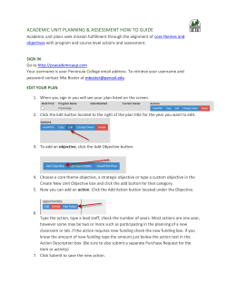
EDMによる操作画面 の一例
(SNS Linac test)
(Matthias Steiner, Nat'l Superconducting Cyclotron Lab., Michigan State University)
導入
EDMは対話的なGUI構築プログラムでありまた
実行エンジンでもある。EPICSの用語法ではこれ
らはDisplay managerと呼ばれる。
ORNL EPICS communityによって保守されてい
る。
コンポーネントベースであり、他のEPICSコラボレ
ーション参加者によって拡張可能である。
拡張可能の意味するところ:
すべての”オブジェクト”は共有ライブラリからロー
ドされる。
EDM管理者はEDMそのものを再コンパイルする
ことなく、提供するオブジェクトのリストからオブジ
ェクトを追加したり削除したりできる。
オブジェクトは世代管理されている。:注意深く実
装されたオブジェクトは既存のディスプレイ画面
に影響することなくアップデート可能である。
EDM Main Window
メニュー・バーだけが意味を持つ。ウィンドウの残
りは使われていない。:
–
–
–
–
File/New – 新しいディスプレイ窓をつくる。
File/Open – 既存のディスプレイを開く。
Path – EDMDATAFILES環境変数に指定されたディレ
クトリのうち一つを選ぶ。
Help – 多くの編集機能や多くのオブジェクトの属性を
説明する。
Display Menu File Operations
With
no objects selected(!)
in a display screen,
click the
middle mouse button
on the display background
This menu pops-up
Save
Save As…
Close
Open…
Open User File...
and:
Switch between
edit and
execute mode
File Operation Notes
ファイル拡張子(.edl)をopen/save操作の際
にファイル名に付ける必要なない。
既存ファイルに対する“Save As…” はユー
ザの確認を必要とする。
新たなプロジェクト...
環境変数の設定
–
Example at end of this slide set, see also online help
Edmの起動: type “edm”
新規ディスプレイの作成: Menu File/New
ディスプレイ属性の設定 (middle button menu) お
よび既定フォントと色の設定
ディスプレイ scheme を default.schemeとして保存
EDMを終了
Creating/Editing Displays
All mouse buttons, many keys and most of
the conceivable combinations of
shift/ctrl/double-click are used!
Takes some getting-used-to, but in the end
allows for very efficient editing.
If lost: Press ESC, left-double-click
somewhere on the display where there is no
object.
Creating Objects
Left mouse button drag to
“rubberband” initial object size
Selecting Objects
Left button click
–
Single exclusive select: object is selected,
currently selected objects are deselected
Shift-left button click
–
Single inclusive select: object is added or
removed from the current group of selected
objects
Selecting Objects (cont)
Control-left button click
–
If only one object is currently selected then
selection cycles among overlapping objects
click
click
Selecting Objects (cont)
This convenient idea was
adopted from AutoCad…
Middle button drag - objects are added or
removed from the current selection group
Top-left to bottom-right:
Select enclosed objects
Bottom-right to top-left:
Select enclosed corners
Again:
Left button rubberband: Create new object
Middle button rubberband: Select objects
Editing Objects: Property Dialog
left click on
selected object
Note:
Property dialog varies
with Object type…
Moving Objects
Place mouse cursor
on interior of one
object
Press left button and
drag objects to new
location
Release mouse
button
Resizing Objects
Place mouse cursor
on control point
of one object
Press left button and
drag to new size
Release mouse
button
Draw/Move/Resize Notes
Fine control may be achieved on moves
and resizes by using keyboard arrow keys
(mouse button release or click ends op)
Control key forces move (prevents resize)
(Useful for tiny objects where you cannot click “inside”
w/o hitting the resize handles)
Shortcuts to options in the Display Properties
–
–
–
–
M/m key turns ON/off orthogonal move
L/l key turns ON/off orthogonal line draw
G/g key turns ON/off grid
S/s key turns ON/off snap-to-grid
Alignment Operations
Reference Independent
–
–
–
Align left, right, top, bottom
Distribute: vert axis, horiz axis
Distribute Midpoint: vert axis, horiz axis
Reference Dependent
–
–
Center: horizontal, vertical, both
Size: width, height, both
Reference Dependent Operations
First object selected is used as reference
If no reference object is specified, an
appropriate object is chosen (topmost,
leftmost, etc.)
Example Align Operation
Select
Reference
Select
Remaining
Click middle
button on display
background and
choose Center...
…On vertical axis
Misc. Operations
Raise, Lower
Copy, Cut, Paste
Group, Ungroup
Flip H & V
Rotate CW & CCW
Group Edit
Undo
Editing Notes
Clicking on one of a group of selected
objects brings up the property box for each
object, one-by-one, as the OK button is
pressed.
To minimize mouse movement, instead of
clicking OK, Apply, or Cancel, you may
double-click the left, middle, or right button
respectively.
Undo
Most useful for move, resize, & alignment
operations
Current limitations:
–
–
Cannot undo edit operations
Cut, Group, and Ungroup : Flush undo stack
A bit different: Creating Lines
left click
click
click
shift-click
or
double click
Left mouse button drag
Editing Line Properties
left click on
selected object
Menu Appears
Choose Edit
Line Properties
Editing Line Segments
left click on
selected object
Menu Appears
Choose Edit
Line Segments
Editing Line Segments (cont)
Left-click
Add point
Shift-middle-click Delete last point
Middle-drag
Move point
Shift-left-click
or
Left-double-click
Terminate edit
operation
Group Edit
Change visual attributes of all selected
objects
Change PV names for all selected objects
EDM Objects
Graphics:
Rectangle
Monitor:
Meter
Control:
Slider
Control:
Text Entry
Control:
Button
Monitor:
Text Update
Control:
Exit Button
Object Categories
Graphics
Do not require a process variable
– Lines, rectangle, circle, arc, text, gif, png, dynamic
symbol
Monitors
Display current value of process variables
– Meter, bar, message box, symbol, text update, strip
chart
Controls
Modify value of process variables, change displays
– Text, slider, button, menu button, message button, updown button, related display, shell command, …
Online Help
Process Variables
Many EDM objects accept PVs to
–
–
–
show the PV value (Monitors)
control the PV value (Controls)
change color or visibility based on the PV (all types)
Format:
–
–
–
–
EPICS\fred
Use EPICS ChannelAccess to connect to “fred”
fred
Use default method which is “EPICS” same as above
CALC\sum(fred, 2)
Use CALC PV “sum”, provide arguments “fred” and “2”.
XY\fred
Use method XY (not implemented)…
“CALC” PVs
–
–
–
CALC: Formula ala CALC record
Selected via prefix “CALC\”
(default is EPICS = Channel Access)
Examples:
–
# File calc.list
# sum(A,B)
sum
# Implementation:
A+B
# F2C(A)
F2C
(A-32)*5/9
Convert Deg.F into Deg.C inside EDM:
“CALC\F2C(EPICS\temp_F)”,
–
Volume of Martini from ingredients:
“CALC\sum(gin,CALC\sum(water,tonic)
)”
Currently, only few objects accept “CALC” PVs
Specifying Color
Color may be specified
visually or by name
Online help explains the
current color file format
The color palette dialog
shows names as
“tooltips”
Decoration or
Meaning?
Example:
The same shade of red
might be available as
both “red” and
“Monitor: MAJOR”.
Pick the one that fits the
desired purpose.
Color - Static and Dynamic
Some color entries are dynamic and are
associated with a color rule
In execute mode, dynamic colors change as
a function of the color rule operating on the
current value of an associated PV
When selecting “alarm sensitive”, the color
will change based on the PV alarm severity.
Color - Static and Dynamic
Colors may be specified for various object
attributes and appear as one or more buttons in
object property dialog boxes. Dynamic colors are
differentiated from static colors in the following
manner:
Static
Dynamic
For a definition of the color, refer to the colors.list
file and the online help
Color Rules
Color Rules are defined in the edm color.list file. The
following is an example of a rule:
rule Red-or-Blue
{
<5
: red
>=5
: blue
}
–
This color will be “red” or “blue” depending on the value of the
PV.
Some objects provide a separate “Color PV” that can be
used instead of the “main” PV for rule evaluation.
EDM Macro Expansion
Macro symbol sources
–
–
–
Command line
Related Display parameter
Multiplexor Object
At run-time, symbol expands to associated
value
e.g. command line option “-m ‘one=1’
at run-time, $(one)
1
Symbols
EDM implements a primitive symbol
facility
Symbols are multi-state objects where each
state maps to a value range of an associated
EPICS PV
64 states max, color and size may be
changed per symbol instance if so desired
Symbols (cont)
An EDM symbol is nothing more than a standard
display file where each symbol state is represented
as a group of objects
Only one grouping level is allowed
The visual ordering corresponds to the ordering of
states
EDM contains an auto-make symbol command to
perform the grouping and ordering
Creating Symbols
1. Create a rectangle corresponding to the geometric boundaries of the symbol,
check the invisible attribute of this rectangle
2. Draw the invariant visual components of the symbol
3. Copy this information and paste it N times, you now have N+1 visual states
Creating Symbols (cont)
4. Draw the state dependent visual components, the first state should be the
out-of-band state, the second state is displayed in edit mode
5. Make sure no grouped objects exist, click the middle mouse button
on the display background, and choose Auto make symbol from the menu
6. Save the EDM display file, this file may now be used as a symbol file
Deploying Symbols
A symbol instance is created like any other
EDM object
One property of a symbol instance is the
symbol file name; this is the file discussed
previously
An exercise will illustrate this entire process
in detail
Other Display Objects
Shell Command
–
Used to execute other programs from EDM
Environment Variables: Example setup
# Helpers
export EDMCFG=/home/T1/EDM
export EDMBIN=/cs/epics/extensions/src/edm
# Essential EDM variables
export EDMFILES=$EDMCFG
export EDMOBJECTS=$EDMCFG
export EDMPVOBJECTS=$EDMCFG
export EDMHELPFILES=/cs/epics/extensions/src/edm_cvs/helpFiles
# EDM search path:
# Local, shared data files, ...
export EDMDATAFILES=.
if [ `echo $LD_LIBRARY_PATH | grep -c $EDMBIN` -eq 0 ]
then
export LD_LIBRARY_PATH=$EDMBIN:$LD_LIBRARY_PATH
fi
alias edm=$EDMBIN/edm
Program Execution - Command Line Options
Define macro replacement
-m “var1=value1,var2=value2,…”
( referenced as $(var1) and $(var2) )
Execute mode
-x
(-noedit)
Typical for operations:
edm -x -noedit -m “var1=1,var2=2” displayFile
Summary
EDM is not only one of the available EPICS
display managers
–
–
EDM has many useful editing features to
support efficient display manipulation
List of EDM objects can be extended, even new
PV types can be added
Exercises
For all excercises, know where you are!
e.g. change to
<your training dir>/testApp/edm
In most cases, edm will load & save files from there. Only for color
and default schemas will it go to the $EDMFILES directory
Know who you are (training user t1, t2, …) and
what IOC you are using, then start edm as
edm –m “user=t3” &
Exercise 1- Start, Display Schemes
Execute edm: Type something like edm –m “user=t3” &
Create a new display: File/New
Invoke the middle(!) mouse button menu, select “Display Properties”
(with the left(!) mouse button).
Select default fonts and colors, Click OK
Invoke the middle-button menu again, select Save Display Scheme,
make the file name default.scheme
Note: Assert that you save it in your training directory!
From the main window, choose File/Exit.
Note: There will be a warning because you didn’t save the display.
That’s OK: We don’t care about the display, we only wanted to create a
“Scheme”!
Exercise 2 - Editing
Execute edm, create a new display
Apply the default.schema from Exercise 1:
Middle-button menu, “Load Display Scheme…”
Save the display as “example2”
(from now on, save every once in a while just in case…)
Create
– two Labels (Graphics/Static Text) with font “Helvetica” 18pt.
Note: The “Auto Size” option of the “Static Text” might be more
confusing than helpful in the beginning. Disable it for now.
–
two Monitor/Textupdate objects, for PV names use e.g.
“t1:aiExample” and “t1:calcExample”.
Note: Try “t2:….” if you are user “t2” and so on.
–
one Graphics/Rectangle, make it “filled”
Note: To change the stacking order, select objects, then use the middlebutton menu to raise or lower them.
Exercise 2…
Use Select, move, resize, align, …
until the display looks a bit like the example shown on this
slide
(it’s shown in execute mode)
These help to finish quicker:
– Display Properties: snap-to-grid, ortho move & line
draw
– Copy/paste
Switch to “execute” mode: de-select all objects,
click the middle mouse button, and choose execute
from the menu
Exercise 3
– More Editing
Create a new display,
save it as example3
Unless you already remember everything: Launch
Help/Line Objects
Use Graphics objects
(circles, text and mostly lines)
to create some of the elements you see in the
screenshot
–
Hint: Arrowheads are “filled” lines
Select several objects at once, change color or font
or … via the “Edit/Display Properties” option
Exercise 4 - PVs
Execute edm and open example2
Save the display file as “example4”
From the example2. there should be a text update for the record
“t1:calcExample” (use “t2:calcExample” if you are user “t2” etc.)
Add a Monitor/Meter uses the same PV “tx:calcExample” - execute
Add a text entry control to the .CALC field of the record:
Create a Control/Textentry, use “t1:calcExample.CALC”
as a PV name.
Add a Control/Menu Button to the .SCAN field of the same record
(e.g. PV name “t1:calcExample.SCAN”) - execute
Add a text update that displays a calculated PV, e.g.
“CALC\sum(t1:calcExample, 2)” - execute
Exercise 5 – Colors, Macros
Execute edm with the option
“-m user=t1” (or t2, t3, t4, …).
Open last example, save as “example5”
Add a label (Graphic/Static text) that shows “User $(user)”
Add two Control/Related Display buttons
–
–
Add a text entry control
–
Set “File” to “relatedDsp”, Macros to “param=1”,
Button Label to “Rel. 1”
Config. Of second button:
File: relatedDsp, Macros:param=2, Button Label: Rel. 2
Obtain the Control PV name from an instructor or use “t1:aoExample”.
This same PV name will be used in a color rule inside the related display
Add an exit button. Check the “Exit Program” option.
Exercise 5…
Create a new display for the related display, save it
as “relatedDsp”
–
–
–
Create a static text object with Text Value set to
“Related Display, param=$(param)”
Create a rectangle, choose a dynamic color for line
color, use the PV name from above
Create an exit button. Do not check the “Exit Program”
option.
Save the relatedDsp and close the display window
Exercise 5…
Execute “example5”
Click the Related Display button, the associated display
should appear and the static text object should display the
symbol value
Change the value of the PV from the example1 text
control, the rectangle color should be determined by the
color rule
Click the Exit Button on each related display.
Click the Exit Button on “example5”, the main screen.
Exit edm?
Exercise 6: Symbols
Create a new display, save it as “switch”
Follow the “Creating symbol” slides to create the
states of a simple switch:
–
kaput, open, closed
Details:
–
–
–
–
Create invisible rectangle
Draw invariant symbol components
Copy image and paste two copies to the display
Draw state dependent components
Exercise 6
–
–
–
–
Arrange images in a rows/columns ordering, first state is upperleft, last is lower-right
If any objects have been grouped, ungroup now
Click middle button, choose Auto make symbol
Save symbol file as switch & close the display.
Create new display “example6”
–
Add text entry to control e.g. “t1:aoExample”
–
Add a symbol instance (Monitor/Symbol)
Use symbol file recently created, use same PV as referenced in text
entry object. Select 3 items, configure each as follows:
Item 1: 0 <= PV value < 1
Item 2: 1 <= PV value < 2
Item 3: 2 <= PV value < 3
Execute example6
Exercise 7: Command Button
Open any of the examples
Add a shell command button to start StripTool
Execute
Note how you can drag & drop (middle button)
PV names from an edm object to StripTool’s
channel name field
© Copyright 2026 ExpyDoc