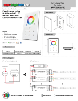
DVB-C8080CL
COMPACT DIGITAL
RECEIVER
FRONT PANEL
1. Status indicator/ remote sensor
2. Menu entry/ exit
3. 4. Channel up or down/ cursor movement
5. Volume decrement/ operation confirmation
6. Volume increment/ menu goes back
REAR PANEL
1. Plughole, power cord
2. Terminal, audio signal output, R
3. Terminal, audio signal output, L
4. Terminal, video signal output
5. Terminal, CABLE IN. Signal Input
6. Terminal, CABLE OUT. Signal loop out for connection to TV for Analog
2
REMOTE
It’s recommended to operate each function of the keys on the Receiver by
using the key on the remote controller. Please read this section to lend itself
to advance your understanding of the function of the Receiver.
STANDBY
FAV
MUTE
0-9
Instruct the receiver t o e n t e r into
standby mode or recover to normal viewing
mode
Display FAV LIST available on the STB.
Mute the audio or resume audio playback.
In Menu for inputting the value
In Non-menu, for channel selection
MENU
Menu entry
EPG
Non-menu, enters EPG interface, press the OK key to
switch cursor from columns of channel and program
LIST
Non-menu, enter TV LIST interface
EXIT
MENU, return to the last grade interface
UP/
DOWN
In MENU, cursor movement
In Non-menu, channel changing
LEFT/
RIGHT
In MENU, state alteration
In Non-menu, volume adjustment
OK
In MENU, operation confirmation
In Non-menu, TV LIST
V+/-
Volume adjustment
3
P+/TV/
RAD
BACK
INFO
Normal operation channel change; page change in list mode
Non-menu, switch channel mode between TV and radio
MENU, go back; Non-menu, channel recall
Non-menu, display an information bar of the present channel,
press the key once more to display its brief description
AUDIO
Non-menu, display audio options, press the directional key
to opt for an option, press the OK key to confirm, press
the EXIT key to exit
GAME
Non-menu, display game options
HELP
Non-menu, display STB information
F1-4
Special functional keys in certain situation
TV
CONTROL
Please read the instructions on the back lid of the remote
PRECAUTIONS ABOUT BATTERIES
Improper use of batteries may cause corrosion or fluid leakage. Please observe
the following instructions for the safe use of batteries
1. Do not mistake the polarities (+ve and –ve ends) of batteries.
2. Never leave dead batteries in the remote control.
3. Remove batteries from the remote controller if is not going to be used for a
long time.
4. Do not attempt to disassemble, short-circuit, heat recharge or expose the
batteries into the fire.
5. Do not use a new battery & an old one together, or the one which is different
type.
6. While replacing the batteries wipe away any electrolyte fluid inside the remote
controller, and then insert new batteries.
4
CONNECTION
1. Connect the audio and video output terminals with the corresponding input terminal
on a TV set
2. Insert the digital antenna cable into the [CABLE IN] terminal on the rear panel;
please notice that the connection effect should effectual
3. The [CABLE OUT] loop out terminal needs to be connected to RF IN input on a TV
set to provide RF signal for viewing Analog Channels.
4. Don't bundle the antenna cable with a power cord as it can cause interference
1. Insert the Input cable into the
[CABLE IN] terminal on the rear
panel of the receiver.
3. Connect one end of red
terminal on a RCA cable to the
AUDIO R output on this receiver
and the other end to the AUDIO R
input on TV set; Connect one end
of white terminal on a RCA cable
to the AUDIO L output on this
receiver and the other end to the
AUDIO L input on a TV set
4. Plug the connector of the
adapter into a socket and insert
its another terminal into the
plughole of the receiver.
5
SIGNAL
TYPICAL CONNECTION
2. Connection one end of yellow
terminal on a RCA cable to the
VIDEO output on this receiver
and the other end to the VIDEO
input on a TV set
CHANNEL MANAGER
On Main Menu, highlight instruction of
Channel Manager, use L/R key to enter
or exit its sub-menu right side.
1. Auto Scan. Highlight [Auto Scan].
Press the OK key to start searching
automatically.
After searching, the screen goes back to
its program-viewing mode. Press the
UP/DOWN key to change channel and
the LEFT/RIGHT key to adjust volume.
2. Manual Scan. Highlight [Manual Scan];
press the OK key to enter its submenu.
Set NET Scan as Yes to scan channels
by net, set NET Scan as No just to scan
channels by the set parameters.
Input Frequency and Symbol Rate value
by pressing the digital keys on the
remote, set Qam Mode by pressing the
L/R key.
As for the concrete parameter value, please contact local Cable
Operator.
3. Delete All Channels. This instruction is
designed to remove all channels
scanned down, after pressing the OK
key, input pin (0000) to go ahead, a
warning box appears to query whether or
not to remove all the existing channels.
Use OK instruction to remove all.
6
CERTIFICATE OF WARRANTY
This certificate of warranty should be produced for servicing under the
terms of the warranty.
CONDITIONS OF WARRANTY
1) Within one year from the date of purchase, if any component(s) is found to be
defective due to faulty workmanship or defective material made, repairs will be
executed free of charge and defective part will be replaced.
Parts repaired or replaced are under warranty throughout the remainder of
the original warranty period only. Repairs under warranty may also be carried
only by authorized service centres or the authorized local cable operator.
2) This warranty does not cover any form of damage resulting from accident,
misuse, application of
incorrect
voltage
or
any
use
contrary
to
the
arising
out
of
operating instruction supplied along with the equipment.
3) NO
responsibility
will
be
accepted
for
damage
unauthorized modification or alterations of any nature made to the Digital Set
Top Box.
4) NO claims will be accepted for damage incurred during transit of Digital Set
Top Box.
5) This warranty is not valid if the serial number of the Digital Set Top Box
has been deleted, defaced or altered.
6) This certificate of warranty should accompany the Digital Set Top Box if
service under warranty period is required to be carried out at the authorized
service centres.
7) The STB conforms functionally to the appropriate BIS standards.
7
WARRANTY CARD
Customer Details
Name:
□□/□□/□□□□
Invoice Number& Date:
Purchase Date:
□□/□□/□□□□
Installation Date:
□□/□□/□□□□
Digital Set Top Box
Model Type:
Precautionary measure:
Please ensure that the following bar coded sticker is common between
Set-Top -Box, Retail Box, and this user manual.
InDigital Franchisee /independent cable operator’s Details
Signature: -
Date:
Franchisee/cable operator
8
© Copyright 2024 ExpyDoc