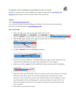
User Guide
Document No:
0017-08-08-01-000 (issue A)
0017-08-08-01-000
MeshWorks™ GUI
INTRODUCTION
MeshWorks is a new turnkey M2M toolset which connects sensors and control peripherals to the cloud.
It simplifies mesh networking systems by implementing a complete platform armed with a python scripting tool that is
fast and easy to use.
CEL’s MeshWorks Graphical User Interface provides a simple yet powerful method to harness the potential of
devices running the MeshWorks scripting framework. This tool enables customers to accelerate time to market by
greatly reducing the design phase of development.
The MeshWorks Graphical User Interface Tool, in conjunction with the MeshWorks firmware, can be used to create
and run simple yet powerful scripts in an easy to use, intuitive way.
This document describes how to install and use the MeshWorks Graphical User Interface Tool.
For more information on MeshWorks, go to www.cel.com/MeshWorks.
Supported Hardware
The CEL MeshWorks firmware supports EM357 devices with attached EPROMs and devices utilizing the EM3588
module.
Referenced Documents/Prerequisites
Category
Document Number
User Guide
0017-08-08-03-000
User Guide
0017-08-08-02-000
Document Name
CEL MeshWorks Firmware CLI Users Guide
CEL MeshWorks Scripting Language User Guide
Prior to running the CEL MeshWorks Graphical User Interface, the following should be performed:
• Software: The CEL MeshWorks firmware should be loaded onto all compatible target hardware.
• Hardware: A compatible device should be connected to the PC via the USB cable.
This document is subject to change without notice.
Document No: 0017-08-08-01-000 (Issue A)
Date Published: June 17, 2014
1
MeshWorks™ User Guide
TABLE OF CONTENTS
Introduction ................................................................................................................................................. 1
Supported Hardware................................................................................................................................. 1
Referenced Documents/Prerequisites ...................................................................................................... 1
Installation ................................................................................................................................................... 4
Installing the CEL MeshWorks Graphical User Interface ......................................................................... 4
Installing the MeshWorks USB-to-UART Driver and attaching hardware ................................................ 4
Installing the USB Drivers ..................................................................................................................... 4
Installing New Hardware On The Host Computer ................................................................................ 5
Locating the COM Port Assignment ..................................................................................................... 5
The CEL MeshWorks Graphical User Interface Program ....................................................................... 6
Scripting Window ...................................................................................................................................... 6
New Script Button ................................................................................................................................. 7
Open Script Button ............................................................................................................................... 7
Search Script Button ............................................................................................................................. 8
Print Script Button ................................................................................................................................. 8
Save Script Button ................................................................................................................................ 8
Check Script Button .............................................................................................................................. 8
Network Map............................................................................................................................................. 8
Event Log.................................................................................................................................................. 9
Script Ninja – Script Generation Tool ..................................................................................................... 10
Application Name.................................................................................................................................... 12
Gateway Selection Dialog ...................................................................................................................... 12
Device Name Dialog ............................................................................................................................... 13
Sleepy Device Dialog.............................................................................................................................. 13
Data Collection Dialogs .......................................................................................................................... 13
Data Point Presence Dialog ................................................................................................................ 14
Data Point Name Dialog ..................................................................................................................... 14
Data Point Type Selection Dialog ....................................................................................................... 15
Data Point Value Dialogs .................................................................................................................... 15
Digital Data Point Values Dialog ......................................................................................................... 15
Analog Data Point Range Dialog ........................................................................................................ 16
Data Point GPIO Selection Dialog ...................................................................................................... 16
Data Point Callback Function Dialog .................................................................................................. 17
Data Point Configuration Complete Dialog ......................................................................................... 17
Control Point Dialogs .............................................................................................................................. 17
Control Point Presence Dialog ............................................................................................................ 18
Control Point Name Dialog ................................................................................................................. 18
Control Point Type Selection Dialog ................................................................................................... 19
Control Point Value Dialogs ................................................................................................................ 19
This document is subject to change without notice.
Document No: 0017-08-08-01-000 (Issue A)
2
MeshWorks™ User Guide
Digital Control Point Values Dialog ..................................................................................................... 19
Analog Control Point Range Dialog .................................................................................................... 20
Control Point GPIO Selection Dialog .................................................................................................. 20
Control Point Callback Function Dialog .............................................................................................. 21
Control Point Configuration Complete Dialog ..................................................................................... 21
Script Complete Dialog ........................................................................................................................... 22
Revision History ....................................................................................................................................... 23
This document is subject to change without notice.
Document No: 0017-08-08-01-000 (Issue A)
3
MeshWorks™ User Guide
INSTALLATION
Installing the CEL MeshWorks Graphical User Interface
The MeshWorks graphical user interface is built as an executable Java JAR file. As such, no formal program
installation is required. All that is necessary to run the program is a compatible Java installation on the host PC. The
MeshWorks graphical user interface is designed and built to run with Java™ SE Runtime Environment (build
1.7.0_51-b13) or higher.
Installing the MeshWorks USB-to-UART Driver and attaching hardware
In order to connect a supported CEL device to the PC through the USB port, it is necessary to install the
MeshWorks USB-to-UART driver (if it has not already been installed). Do not connect the CEL MeshWorks device
to the computer prior to running the USB driver installation. The USB driver installation must be completed outside of
the CEL MeshWorks software tools installation.
The USB driver installation is a two-step process. The first step installs the USB drivers, such that when
a
valid
device is detected the drivers are automatically installed. The second step is the automatic installation of the drivers.
Installing the USB Drivers
The following procedure describes how to install the USB drivers:
1. Double-click the CelVCPInstaller_x86.exe executable (or CelVCPInstaller_x64.exe for 64-bit versions
Windows).
2. When the CEL MeshWorks USB Bridge Driver Installer dialog is displayed, click Next.
Figure 1
If prompted by an Open File / Security Warning dialog box, click Install this driver software anyway.
This document is subject to change without notice.
Document No: 0017-08-08-01-000 (Issue A)
4
MeshWorks™ User Guide
Figure 2
3. Once the installation has completed successfully, click Finish.
Figure 3
Installing New Hardware on the Host Computer
1. Once the USB Driver installation is complete, connect the MeshWorks device to an available USB port on the
host computer. The MeshWorks device interface is powered directly from the USB interface.
2. The device should be detected and the driver installed automatically.
3. The hardware drivers for the USB-connected MeshWorks device have now been successfully enumerated.
Locating the COM Port Assignment
Once the USB driver has been successfully installed, a Virtual COM port has been created. In order to interface to
the MeshWorks Graphical User Interface, the COM port assignment is needed. The Windows Device Manager can
be used to identify the assigned COM port as well as verify that the drivers have been properly installed. To
determine which COM port has been assigned to the device, please follow the steps listed below:
1
2
3
Right-click on the My Computer icon on your computer’s desktop, or the My Computer entry from the Start
Menu.
Select Properties. The System Properties window will be displayed.
Click the Hardware tab and then click the Device Manager button. The Device Manager will be displayed.
Scroll-down and expand the Ports (COM & LPT) section; one of the items in the list of available ports should
This document is subject to change without notice.
Document No: 0017-08-08-01-000 (Issue A)
5
MeshWorks™ User Guide
read CEL MeshWorks USB Bridge (COM#), where # is the assigned COM port. In the screenshot
Figure 4, the assigned COM port number is 50.
shown in
Figure 4
THE CEL MESHWORKS GRAPHICAL USER INTERFACE PROGRAM
This section details the functionality of each of the sub widows in the MeshWorks Graphical User Interface Program.
Scripting Window
The MeshWorks scripting window is at the top-left of the CEL MeshWorks Main Window (see Figure 5).
This document is subject to change without notice.
Document No: 0017-08-08-01-000 (Issue A)
6
MeshWorks™ User Guide
Figure 5
The scripting window is where new scripts can be written, existing scripts on the host PC displayed/edited and also
where scripts read from devices in the Network Map window are displayed.
New Script Button
Figure 6
The “New Script” button (highlighted in Figure 6) will clear all of the text in the scripting window so a new script can
be written from scratch.
Open Script Button
Figure 7
The “Open Script” button (highlighted in Figure 7) will bring up a file browser dialog where a script file in the host PC
can opened and displayed in the scripting window.
This document is subject to change without notice.
Document No: 0017-08-08-01-000 (Issue A)
7
MeshWorks™ User Guide
Search Script Button
Figure 8
The “Search Script” button (highlighted in Figure 8) will bring up a Find/Replace dialog where a search string can be
entered in the scripting window to be found and/or replaced by another string.
Print Script Button
Figure 9
The “Print Script” button (highlighted in Figure 9) will bring up a Print dialog where the user can select which device
will print the contents of the scripting window.
Save Script Button
Figure 10
The “Save Script” button (highlighted in Figure 10) will bring up the save script dialog where the user can select a
file on the host PC file system to where the contents on the scripting window are written.
Check Script Button
Figure 11
The “Check Script” button (highlighted in Figure 11) will pass the contents of the scripting window to the integrated
script parser. The script parser will check the script for certain errors (syntax, empty lists, etc.). This helps to ensure
that the script in the scripting window will parse and run successfully on the target device.
Network Map
The MeshWorks network map window is on the right side of the CEL MeshWorks Main Window (see Figure 12).
This document is subject to change without notice.
Document No: 0017-08-08-01-000 (Issue A)
8
MeshWorks™ User Guide
Figure 12
The network map window displays all discovered devices in the network; along with information stating the total
number of devices on the network, the network channel and the network PAN ID.
Event Log
The MeshWorks event log window is at bottom-left side of the CEL MeshWorks Main Window (see Figure 13).
This document is subject to change without notice.
Document No: 0017-08-08-01-000 (Issue A)
9
MeshWorks™ User Guide
Figure 13
The event log window displays all the system messages received by the attached device. This can provide useful
information regarding network and system operation. Additionally, the logs can be saved for later review or analysis.
SCRIPT NINJA - SCRIPT GENERATING TOOL
The MeshWorks Graphical User Interface Tool includes the Script Ninja; a sub application to assist in the creation of
scripts by walking the user through the process with simple step-by-step questions.
This document is subject to change without notice.
Document No: 0017-08-08-01-000 (Issue A)
10
MeshWorks™ User Guide
Figure 14
Click on the “Script Ninja” button highlighted in Figure 14 to launch the Script Ninja application.
Figure 15
This document is subject to change without notice.
Document No: 0017-08-08-01-000 (Issue A)
11
MeshWorks™ User Guide
Application Name
Figure 16
The application name defines the network group the device(s) will operate in. This name is used to generate the
network access key, so all devices with the same application, but only those devices, will automatically join the
same network.
Gateway Selection Dialog
Figure 17
The Gateway Selection Dialog determines whether the device the script in progress runs on will be the network
gateway. This is similar to a network coordinator. The device running the gateway script will form the network on an
available channel, pick the network PAN ID and generate the network key based on the application name provided
earlier. Each network can only have one active gateway device per application at any given time.
This document is subject to change without notice.
Document No: 0017-08-08-01-000 (Issue A)
12
MeshWorks™ User Guide
Device Name Dialog
Figure 18
The Device Name Dialog allows the user to specify a unique name for each device in the network. This name
should be something that is easy to distinguish from other devices.
Sleepy Device Dialog
Figure 19
The Sleepy Device Dialog allows the user to specify whether a device will be powered on at all times or will operate
on a sleep/wake cycle.
Data Collection Dialogs
This document is subject to change without notice.
Document No: 0017-08-08-01-000 (Issue A)
13
MeshWorks™ User Guide
Data Point Presence Dialog
Figure 20
The Data Point Presence Dialog allows the user to add one or more data collection points. These will represent
physical input points attached to the device. Some examples include: buttons, reed switches, I2C sensors and ADC
voltage inputs.
Note that even if a device has a data collection point, but its functionality is not desired in a particular script, it does
not have to be added to the list of collection points in that script.
Data Point Name Dialog
Figure 21
The Data Point Name Dialog allows the user to assign a friendly and/or meaningful name to the data point being
defined. For example, if the device has 2 buttons, the data point names could be leftbutton and rightButton instead
of simply input 1 and input 2.
This document is subject to change without notice.
Document No: 0017-08-08-01-000 (Issue A)
14
MeshWorks™ User Guide
Data Point Type Selection Dialog
Figure 22
The Data Point Type Selection Dialog is where the user specifies the type of input this data point will be. Current
choices are digital (push buttons, reed switches, etc.), analog (ADC) and I2C.
Digital Data Point Values Dialog
Figure 23
The Digital Data Point Values Dialog allows the user to assign a meaningful name to the 0/1 digital input states. For
example: up/down or on/off.
This document is subject to change without notice.
Document No: 0017-08-08-01-000 (Issue A)
15
MeshWorks™ User Guide
Analog Data Point Range Dialog
Figure 24
The Analog Data Point Range Dialog allows the user to specify the expected range for the analog input. For
example, ADC voltages could be 0 – 1.2.
Data Point GPIO Selection Dialog
Figure 25
The Data Point GPIO Selection Dialog allows the user to specify the GPIO pin on the MeshWorks device where the
data collection point is physically attached.
If the MeshWorks GUI user does not have this information, they should contact their device manufacturer.
This document is subject to change without notice.
Document No: 0017-08-08-01-000 (Issue A)
16
MeshWorks™ User Guide
Data Point Callback Function Dialog
Figure 26
The Data Point Callback Function Dialog allows the user to specify a name for the callback function that will be
called at the specified interval. The user will have to edit the generated script to complete the definition of this
callback function. In this function, the user may read the value of the data point, report any change in the data point
state/value to the network gateway or perform local and/or remote operations (i.e. turn on/off a local/remote LED).
For more information, please refer to the available sample scripts.
Data Point Configuration Complete Dialog
Figure 27
The Data Point Configuration Complete Dialog indicates that sufficient information about the current data point has
been collected and allows the user to go back to make changes or to decide whether another data point shall be
added.
Control Point Dialogs
This document is subject to change without notice.
Document No: 0017-08-08-01-000 (Issue A)
17
MeshWorks™ User Guide
Control Point Presence Dialog
Figure 28
The Control Point Presence Dialog allows the user to add one or more control points. These will represent physical
control/output points attached to the device. Some examples include: LEDs, buzzers and PWMs.
Note that even if a device has a control point, but its functionality is not desired in a particular scripts, it does not
have to be added to the list of control points in that script.
Control Point Name Dialog
Figure 29
The Control Point Name Dialog allows the user to assign a friendly and/or meaningful name to the data point being
defined. For example, if the device has 2 LEDs, the data point names could be greenLed and redLed instead of
simply LED1 and LED2 or input 1 and input 2.
This document is subject to change without notice.
Document No: 0017-08-08-01-000 (Issue A)
18
MeshWorks™ User Guide
Control Point Type Selection Dialog
Figure 30
The Control Point Type Selection Dialog is where the user specifies the type of output this control point will be.
Current choices are digital (LEDs, relays, etc.), analog (PWM) and I2C.
Control Point Value Dialogs
Digital Control Point Values Dialog
Figure 31
The Digital Control Point Values Dialog allows the user to assign a meaningful name to the 0/1 digital output states.
For example: up/down or on/off.
This document is subject to change without notice.
Document No: 0017-08-08-01-000 (Issue A)
19
MeshWorks™ User Guide
Analog Control Point Range Dialog
Figure 32
The Analog Control Point Range Dialog allows the user to specify the expected range for the analog output. For
example: a PWM buzzer could be 0 – 2000Hz.
Control Point GPIO Selection Dialog
Figure 33
The Data Point GPIO Selection Dialog allows the user to specify the GPIO pin on the MeshWorks device where the
data collection point is physically attached.
If the MeshWorks GUI user does not have this information, they should contact their device manufacturer.
This document is subject to change without notice.
Document No: 0017-08-08-01-000 (Issue A)
20
MeshWorks™ User Guide
Control Point Callback Function Dialog
Figure 34
The Control Point Callback Function Dialog allows the user to specify a name for the callback function that will be
called at the specified interval. The user will have to edit the generated script to complete the definition of this
callback function. For more information, please refer to the available sample scripts.
Control Point Configuration Complete Dialog
Figure 35
The Control Point Configuration Complete Dialog indicates that sufficient information about the current control point
has been collected and allows the user to go back and make changes or to decide whether another control point
shall be added.
This document is subject to change without notice.
Document No: 0017-08-08-01-000 (Issue A)
21
MeshWorks™ User Guide
Script Complete Dialog
Figure 36
Once all data and/or control points are configured, the Script Complete Dialog is presented to the user. Upon
clicking the Next button, the Script Ninja tool will generate a script using the information provided.
This document is subject to change without notice.
Document No: 0017-08-08-01-000 (Issue A)
22
MeshWorks™ User Guide
REFERENCES
Reference Documents
Download
California Eastern Laboratories
0017-08-08-02-000 – CEL MeshWorks Scripting Language User Guide
Link
0017-08-08-03-000 – CEL MeshWorks Firmware CLI Users Guide
Link
REVISION HISTORY
Previous Versions
0017-08-08-01-000
(Issue A) June 17, 2014
Changes to Current Version
Initial Release
This document is subject to change without notice.
Document No: 0017-08-08-01-000 (Issue A)
Page(s)
N/A
23
MeshWorks™ User Guide
DISCLAIMER
The information in this document is current as of the published date. The information is subject to change without notice. For actual
design-in, refer to the latest publications of CEL Data Sheets or Data Books, etc., for the most up-to-date specifications of CEL
products. Not all products and/or types are available in every country. Please check with an CEL sales representative for availability
and additional information.
No part of this document may be copied or reproduced in any form or by any means without the prior written consent of CEL.
CEL assumes no responsibility for any errors that may appear in this document.
CEL does not assume any liability for infringement of patents, copyrights or other intellectual property rights of third parties by or arising
from the use of CEL products listed in this document or any other liability arising from the use of such products. No license, express,
implied or otherwise, is granted under any patents, copyrights or other intellectual property rights of CEL or others.
Descriptions of circuits, software and other related information in this document are provided for illustrative purposes in semiconductor
product operation and application examples. The incorporation of these circuits, software and information in the design of a customer’s
equipment shall be done under the full responsibility of the customer. CEL assumes no responsibility for any losses incurred by
customers or third parties arising from the use of these circuits, software and information.
FOR MORE INFORMATION
For more information about CEL MeshConnect products and solutions, visit our website at www.cel.com/MeshConnect.
TECHNICAL ASSISTANCE
For Technical Assistance, visit http://www.cel.com/MeshConnectHelp
This document is subject to change without notice.
Document No: 0017-08-08-01-000 (Issue A)
24
© Copyright 2026 ExpyDoc