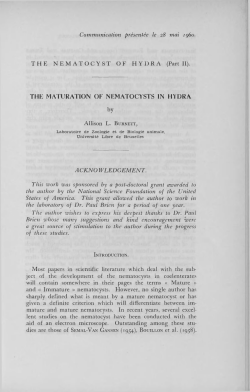
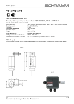
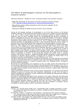
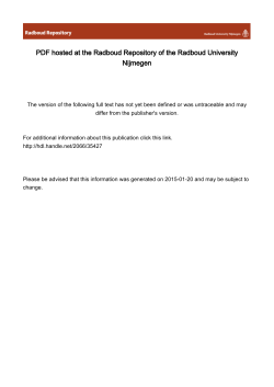
MRT 2150 • Lift height : 2 0 .60 m • Max. reach : 18.10 m • Engine : 150 HP - 110 kw • 4 w heel drive - 4 w heel steer • Hydrostatic transmission • Levelling system V J U MANITDU R O TA TIO N ON S T A B IL IS E R S FU LLY EX T EN D E D W ITH FO R KS F R O N T A L P O SITIO N ON W H EELS W ITH FO R KS R O TA TIO N ON S T A B IL IS E R S N OT FU LLY EX TEN D ED W ITH FO R KS R O TA TIO N ON S T A B IL IS E R S FU LLY EX TEN D ED W ITH 5T W IN CH u 1 3 U J 50 60 70 70 K IL R O TA TIO N ON S T A B IL IS E R S FU LLY EX TEN D ED W ITH JIB P 600 R O TA TIO N ON S T A B IL IS E R S FU LLY EX TEN D ED W ITH JIB P 1 5 0 0 R O TA TIO N ON S T A B IL IS E R S FU LLY EX TEN D ED W ITH EX T E N S IB L E P LA TFO R M 2 ,2 5 / 4 m R O TA TIO N ON S T A B IL IS E R S FU LLY EX TEN D ED W ITH 3 D SYSTEM IN P O S ITIV E P O SITIO N R O TA TIO N ON S T A B IL IS E R S FU LLY EX TEN D ED W ITH A E R IA L JIB P LATFO RM R O TA TIO N ON S T A B IL IS E R S FU LLY EX TEN D ED W ITH 1 0 0 0 KG P LA TFO R M 2 ,2 5 / 4 m R O TA TIO N ON S T A B IL IS E R S FU LLY EX TEN D ED W ITH 3 D SYSTEM IN N E G A T IV E P O SITIO N R O TA TIO N ON S T A B IL IS E R S FU LLY EX TEN D ED W ITH C R A N E JIB 25 24 23 22 21 20 19 IB 17 16 15 14 13 12 11 10 7 6 5 4 3 2 1 O m MRT 2150 0 R R I X / I L .E S E Lift capacity (on sta bilisers). at 500 mm from forks heels .4999 kg Lift height : .20.60 m Tyres 18 - 22,5 Forks (mm) Length.................................................................... 1200 Width x thickness............................................150 X 50 ff Multidisc brakes : hydraulically assisted on both axles Negative parking brake Engine Mercedes-Benz Type............................................... OM 904 LA (EURO 3 Capacity................................................ 4 cyl. 4250 cm3 Power (ISO/TR 14396).........................150 HP/110 kw 580 Nm of 1200 at 1600 rpm Water cooling Direct injection Transm ission.............................................hydrostatic With automatic power regulation (hydraulic variable displacement pump and motor) Reversing s h if t .................................... electromagnetic 2 speed forward and reverse Travel s p e e d .................................................. 36 km/h* *This speed may be limited by local regulations Rear axle Frame levelling on front axle +/- 8° (15%) Automatic rear axle locking system over 15° rotation 4 stabilizers simultaneous or individually controlled Total and continuous rotation Turret mounted on a double slew ring Hydraulic and electric rotation Hydraulics 3 pumps gear t y p e .........................270 bars/160 l/mn Control : 2 electro proportional control joysticks for all hydraulic movements Capacities Cooling system ....................................................... 18 Engine o i l ............................................................... 15 Hydraulic o il..........................................................200 Fuel t a n k .............................................................. 230 l. l. l. l. Weight unladen (with fo rk s ) ...................... 16095 kg Overall w idth..................................................... 2.43 m Overall h e ig h t...................................................3.05 m Overall le n g th ...................................................6.78 m Ground clearance........................................... 0.37 m Drawbar pull................................................ 8200 daN B Standard load moment indicator (mobile crane standards) T his pu b lication in no w ay co n stitu te s an offer and th e co m p a ny reserve s the rig h t to a lte r sp ecification w ithout prio r notice. T he MANITOU m odels presented in this brochure can be supplied com plete w ith optional e q u ipm ent attachm ents. A A1 A2 A3 B C D E F G H I J K L M N O P Q R S T U V Y Z 1200 150 1320 50 290 6490 5050 1155 2750 1155 380 2485 3050 2485 1930 2425 4700 5100 150 4500 3800 4550 4040 6230 950 12° 105° mm C€ MAMTOU BF SA B.P. 249 - 44158 Ancenis Cedex - France Tél.: 33 2 40 09 1011 / Export Department Fax: 33 2 40 09 10 97 www.manitou.com 7 00 3 84 E N -A - 04/07 MANIWU M RT ?.■ - ”'•»■s* JMANITUU Carríage For Floating Forks ( t f f ) • • • • • Height 945 mm W idths 1040 and 1300 mm 2 forks w ith eyes, 1200 mm long Dištance between forks can be adjusted with high precision Used for picking up pallets from uneven ground OPTION: Floating fo rk s w ith integrated side sh ift (TFF) Equipment designed to European standards and to the specifications of your Maniscopic &MANITUU PC 40 — i ¥ j * ( / ° e / — -J . E G GíOÍ CHARACTERISTICS DESCRIPTION PC 40 OVERALL LENGTH LOAD LIMIT 4000 Kq WEIGHT A B C D E F G H I 740 598 470 354 153 156 200 462 484 120 KG Description: 0.50 m long jib with carrying capacity o f 4000 kg iSMANITuU ammans GALVANISED PLATFORM WITH DOOR á Description: Galvanised extendable and rotating personnel platform Specifications: -Maximum load: 365 Kg -Maximum number o f people: 3. -The platform can be extended Írom 2,25 m (closed) to 4,00 m (open) -90°+90° hydraulic rotation. -Door can be opened on one side o f platform. -The platform is accessible from three sides. -The platform can be accessed even if it is not extended. -Presence o f two guides for easy handling by means o f u equipment Safety features: -Overload sensor. -Shear pin presence sensor. -Door closed sensor CH A R A C T ER IS TIC S DESCRIPTION GALVANISEDPLATFORMWITHDOOR O V E R A L L LENG TH LO AD LIMIT 365 KG A A' B 1976 1060 785 C D 1037 640 E F G 1280 2339 500 W EIGHT H I 1150 949 L 400 M 1344 500 K G k'HIANITOU amCHMíHTS m u T h is is u n iv e rsa lly a p p ro p ria te eq uip m en t; its d im e n sio n s, m eeting European sta n d a rd s, m ake it in d isp e n sa b le for m oving p allets o f bricks, ce m e n t o r clad ding. Its use is to ta lly unlim ited . Its sy ste m o f fo rk s is certifie d a cco rd ing to FEM c la s s ific a tio n s . Ju st like o th e r e q u ip m e n t in the M AN ITO U range, du rab ility and sa fe ty are its m a jo r fea tu res. Its floatin g fo rks and th e ir sy ste m o f m o v e m e n t m ake it e x tre m e ly m an ageab le. It is po ssible to a d ju st the fo rks v e ry precisely, and pick up a pa liet from uneven ground. The backboard gives the load gre a t sta b ility and prev e n ts it from slipping backw ards. T h is c a rria g e a lso e n a b le s you to use o th e r e q u ip m e n t in the M AN ITO U range, such as the co n cre te skip w ith sp out, and the fo rk e x te n sio n s (1 .7 0 m to 2.5 0 m). To find out which equipment suits your MANISCOPIC, get in contact with your dealer. The specifications shown here are not binding on the manufacturer and may be altered without notice. ISO 9001 MANITOU BF SA B.P. 249 - 44158 Ancenis Cedex - France Tél.: 33 2 40 09 10 11 / Export Department Fax : 33 2 40 09 10 97 www.manitou.com &MANITUU M RT 1742 M Seu'eá M RT 1850 M RT 2150 ^ R iv / iu e c s e Since 1993 and its first appearance on the market, the MRT range has been confirming its expertise in leading edge technology as the world leader in all-terrain handling equip ment. The «Manitou Rotary Telescope» is a 3 - in - l machine concept, combining 3 main functions: handling, lifting and elevating personnel. Versatile throughout 360°, Site efficiency, working comfort and absolute Safety... are the main advantages of the MRT M and Priviíege Series. The M R T is the a n s w e r to a ll y o u r n e ed s in a ll-te rra in app licatio n. MRT 1432 MRT 1542 MRT 1635 MRT 1742 MRT 1850 MRT 2150 MRT 2540 MRT 3050 M Series M Series M Series M Series Priviíege Priviíege Priviíege Priviíege Lifting height (m) 13.82 14.78 15.82 17.30 17.90 20.60 24.60 29.70 Maximum range (m) 11.63 12.50 13.20 14.50 15,20 18.10 18.50 25.50 3.2 4.2 3.5 4.2 5.0 5.0 4.0 5.0 Nominal capacity on stabilizers (t) L k MRT 2540 r r i v /i l e g e M RT 3050 : R R i\ / » L _ e : c 5 e : >C noHDnouHi 31U V S M 3A i A wide range a Maniscopic Equipped with forks or a bucket, the MRT has all the advantages of a high lift Maniscopic (all-terrain capability, lift capacity and versatility). Material distribution Bridge maintenance a mobile elevated work platform (MEWP) MRTs can be pre-equipped for working with access piatforms, pendulum or 3D arms, for working at heights in excess of 41 metres. Restoration work of accessories for many applications Site supplies Steel erection ■oved ca b in the PRIVILEGE jn with unrivalled comfort. Attachment visibility at height The lack of a front bar and t ie rounded shaoe of the w'ndscreen guarantees excellent visibility wnen working at height. Standard Front/Rearand roof windscreen w:pers ensure oerfect visibility even when iťs raining. Electric windows Driver's cab safety Large storage space Easy io open and close with the press of a button. The shape of the joysticks fits perfectly into the hand. For 'mproved safety, they are ecuipped with a deadmans switch to prevent any risk of uncontrolled Space for ope'ators manuals and P.P.E. tion Equipment). movement. All under control Control and alarm visual indicators M ultifunctional digital display Load S ta tu s Control ler. 1 Hour meter 5 Speed display (km/h) 2 Kilometer counter (only on starting 6 Rev counter (rpm x 10) the machine) 7 Engine warning indicator 3 Water temperature indicator 4 Fuelgauge 8 Speedometer or rev counter selector panel is offset to the right for excellent frontal visibility. Main control panel A Backup pump switch (only if platform pre-equipped) B Remote control switch (optional) C Electric accelerator switch D Parking brake switch E Transmission reset button F Range change switch G Rotating light switch (Personal Protec- m m M — "A P1 Front left stabilizer selector P2 Front right stabilizer selector P3 Rear left stabilizer selector P4 Rear right stabilizer selector Q Stabilizer movement selector Q1 Stabilizer movement indicators S Stabilizer movement control SI Stabilizer movement control Indicators ] Slope corrector joystick P R IV IL E G E i|l6 u a Jis P UB J9 M ° d Hydrostatic transmission It provides accurate and gradual mo vement to position in total safety. Automatic adjustment of the variable flow hydrostatic pump and variable capacity hydrostatic motor provides optimal balance between speed and tractive effort. A two-ratio gearbox means that the operator can choose to work in «site» or «road» modes depending on the terrain. Gearbox Front axle Heavy duty steering axles Designed specifically for all-terrain applications, they provide excellent power transfer to the wheels. The steering cylinders on the upper part are situated above the axle to prevent accidental damage. Protected steering cylinder Variable capacity hydrostatic motor Epicyciic reduction gears Steering axles are equipped with epicyciic reduction gears which multiply wheel torque while reducing internal wear. ■ Oil-bath disc brakes ■ I The automatically adjusting multidisc service brakes are inside the axle assembly. A hydraulic negative action parking brake [ built into this system ensures that the machine will stop under all circumstances. I • Maximum braking capacity always distributed over all 4 wheels. Epicyciic reduction gea'S Electricai circuit protection • Minimum maintenance. Seaied electricai installation The MRT series are IP67 protected to guarantee protection against water and dust penetration. All the electricai components (electronic cards, fuse and relay boxes, connections...) are thereby protected to ensure perfect reliability and longer life. ÄVVWWWYVUM Fast stabilizer deployment The MRT series (1542/1742/1850/2150/2540/3050) have telescopic scissor stabilizer jacks designed by Manitou. Optimal ground support The stabilizer mechanism guarantees permanent contact with the ground in deployed position. With their wide contact area, they adapt to all surfaces, providing maximum stability. Stabilizers within the limits In the raised position, Manitou stabilizers remain within the machine's limits and do not reduce its ground dearance. The cylinders are perfectly protected. A switch in the cab deploys the stabilizers simultaneously or individually. The design of scissor stabilizers ensures that excellent ground clearance is maintained at the feet, even when they are fully deployed. Accurate machine placement is therefore easy and fast. Perfect stability on the stabilizers »Mjwniv | U > l a H n u M l I I ( t in I I I I I I ■ I l l n n l l M Square sta b ilize r base StaMd£ers in intermediate position The telescopic scissor stabilizers form a lifting square which guarantees uniform stability during rotation. Intermediate locking - if there is an obstacle on the site or the machine is in a narrow Street, stabilizers in the intermediate position allows you to work in total safety whil maintainmg impressive capacity. Perfect stability even on tyres To ensure perfect stability and guarantee maximum capacity during rotation on tyres, the MRT is equipped with an automatic rear axle oscillation locking device. Frontal work : Rear axle assem bly oscillating. Flexibility and Precision Precise movement M MUTOU On quadriplex and quintuplex booms, the pentagonal cross-section makes the telescopic boom more rigid and provides perfect guidance between boom sections which considerably reduces lateral oscillation. There are many advantages: • extremely precise movement, • perfect control of the handling operation, • easy access to chain tensioners, • easy wear pad adjustment. Intuitive m anipulation Driver's cab comfort. MRTs are equipped as standard with two electrohydraulic levers mounted on the seat arm-rests to gire better control and greater comfort. The right-hand lever can simultaneously control two movements: lifting and tilting. The left-hand lever can simultaneously control three movements: telescope extension, turret rotation and attachment control. Adjustments to suit every operator: • Seat depth adjustment. • Height adjustment. • Seat back rest adjustment. • Suspension adjustment according to the operator's weight. Turret rotation speed limiter To guarantee total safety on site, MRTs are also equipped with two potentiometers on the left m arm-rest, which control the turret left/right rotation speed maximum height means accurate even the most difficult manoeuvres. Radio-control (optional) All MRTs can be equipped with radio-control. This. means that all the boom hydraulic functions can be performed at a dištance. For maximum ergonomics, the two proportional radio-control joysticks perform the same functions as the driver's cab joysticks and allow simultaneous movement to optimise efficiency. Manoeuvrability The MRT has three steering modes; - All wheel steering for maximum manoeuvrability. - Two wheel steering for road travel. Crab steering for a lateral approach, two wheel Compactness With 4 wheel drive and steering, the tuming circle is very small. Its exdusive design (laterally-mounted engine), makes the MRT extremely manoeuvrable. All-terrain performance The 4 wheel drive and the oscillating rear axle provide excellent adhesion on all four wheels even on rough terrain ground. The hydrostatic transmission coupled to a two-ratio gearbox gives the ability to travel on the most difficult ground conditions including steep slopes. Frame levelling MRT 1850, 2150, 2540 and 3050 are fitted with frame levelling on the front axle (+/- 8°) to ensure loads can be easily handled on uneven ground. The MRT range meets European norms governing mobile cranes, telescopic trucks and personnel elevation. MRTs are equipped with a load status controller (Manitou Safety System) capable of memorising a large number of settings. It constantly analyses the loaďs position and the machine's working configuration. It compares all the data with the memorised load diagrams. In the event of an overload, it automatically cuts aggravating movement. This system eliminates any risk of overloading the machine or its accessory. AN ADVANCED SAFETY SYSTEM ! Sensors are installed on the machine to detect working conditions and configurations. A. Detection of boom angle and extension. B. Detection of load weight. C. Detection of turret position. D. Automatic detection of working configuration. SELF-DIAGNOSIS This Load Status Controller has a specific self-diagnosis programme. It is used to verify on screen the status of all the components connected to the load control system. If there is an incorrect reading, this device goes into safety mode and locks movement. É To facilitate diagnosis, the sensor concerned is displayed on the screen to minimise machine down time. The digital display in the cab informs the operator of m achine load status continuousiy. It also includes: 1, Symbols identifying the machine's operating modes (stabilized, frontal on tyres, rotation on tyres, intermediate position). 5. Symbols for the information displayed. 6. Icon representing the machine. 7. Image contrast adjustment. 2, Symbols identifying the equipment (selection from a drop-down menu accessible via key A). 8. 9. Accessory selection (from those available). 3, Green/Yellow/Red light indicators showing working condition (safety/alarm/locked). 10. Confirmation of the accessory and image contrast value. 4, Alphanumeric LCD display of working data. Detection of load weight ® Hydraulic movement speed selector. Detection of boom angle and extension Detection of boom angle and extension © Detection of turret position Automatic detection of working configuration Tension distributör All MRT Chain booms have a distribution system which ensures even distribution of tension on all the chains, to extend reliability and life span. A mechanical stop device is used for pick-up work with a bucket while keeping the boom retracted. Storage space M MRTs are equipped with a useful storage compartment fora storing of the platform control box, remote control a n d i small ladder plus P.P.E. (Personal protection Equipment) and any additional service items (grease guns, etc). The compartment is fitted with an anti-theft device. Visual indicator Easy access to the main components • The engine Is installed laterally for access on 3 sides. • A cover behind the chassis allows access to the air filter and battery. An indicator on the cab access side is used to check the hydraulic oil level easily. The Manitou network Optimized boom design The use of high-ténsile Steel means that the boom js light and strong. Whether hydraulic or chain driven, MRT telescopic ;booms are desiglapd to facffitfjte and minfmise In your profession and ours, reactivity and professionalism are our strengths. To ensure the best service, we provide you with the most comprehensive global network and most efficient logistics on the market. Our network works hand in hand with the manufacturing plants to provide a complete after sales service, covering all your needs in terms of spare parts and technical services. Training At the 600 Manitou service points throughout the world, nearly 1 000 technicians are trained every year to be real professionals at your service. Spare part avaiiabiiity 95% of Manitou spare parts are shipped throughout the world within 24 hours: A level of response you need. Manitou, material handling world leader In ventor o f the rough terrain fo rklift truck, M anitou offers today the m ost com prehen sive range to m eet all specific handling and personal lifting requirem en ts : MANITOU mmmsm © Rough rerra n and scm i industria masted trucks Telescopic trucks i JL _ j£ Xsj\SLO M AN w m m åå Access equipment MANimim á 3 iTnr^ i S CompacL telescoaic handier / Backhoe/Loader with telescopic bocm MANI Truck mounted fcrkfifts MAmmwms MANILU® Articulateö wheeled oaders Electric pa let truc<s and electric stackers A network of skilled professionals at your service ! With a netw ork of 600 service and parts centres in m ore than 120 countries, M anitou provides an efficient afte r-sa le s support based on the expe rtise of th ou san ds of factory trained technicians. Tne eqjiprrwnr suppseö wftfc eathmodei may »fler from tliat cescrtoed irvine leaftet f a móre dctďb. a ntad y jir MAN! tqu dealer. MANITOU BF SA B.P. 249 - 441SS Ancenis Cecex France Tel. 33 2 <10 09 10 11 Export Department Fax 33 2 4C 0910 97 www.rrianirou.com 7Ú0413EN-A 03/06 MANITOU
© Copyright 2026 ExpyDoc