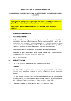
OTEKON’14
7. Otomotiv Teknolojileri Kongresi
26 – 27 Mayıs 2014, BURSA
LOW-COST, EDUCATIONAL INTERNAL COMBUSTION ENGINE
ELECTRONIC CONTROL UNIT HARDWARE-IN-THE-LOOP TEST
SYSTEMS
Sertaç Karaman1, Levent Güvenç*
İstanbul Okan Üniversitesi, Mühendislik ve Mimarlık Fakültesi, Mekar Lab., Makina Müh. Böl., İstanbul
*
ABSTRACT
Different hardware platforms and their associated real time operating systems that can be used in an educational
laboratory for illustrating engine ECU hardware in the loop testing are presented and compared in this paper. A Matlab
graphical user interface prepared for generating synthetic crank and camshaft angular position sensor signals to be fed
to the engine ECU during HiL testing is introduced. This GUI is used to generate faulty sensor signals to check the
response of the engine ECU during HiL simulation. Examples of faulty signals that can be generated with the GUI are
illustrated.
Keywords: hardware-in-the-loop simulation, engine electronic control unit
DÜŞÜK MALİYETLİ, EĞİTİM AMAÇLI İÇTEN YANMALI MOTOR ELEKTRONİK KONTROL ÜNİTESİ
DONANIM İÇEREN SİMÜLASYON SİSTEMLERİ
ÖZET
Bu bildiride bir eğitim laboratuvarda kullanılabilecek içten yanmalı motor elektronik kontrol ünitesi donanım içeren
simülasyon sistemi donanım platformları ve ilgili gerçek zamanlı işletim sistemleri sunulmuş ve karşılaştırılmıştır.
Donanım içeren simülasyon sırasında motor elektronik kontrol ünitesine gönderilmek için sentetik krank şaftı hız
sensörü ve kam şaftı hız sensörü sinyallerini üretmek için hazırlanmış bir Matlab grafik kullanıcı arayüzü tanıtılmıştır.
Bu grafik arayüz donanım içeren simülasyon sırasında, motor elektronik kontrol ünitesi tepkisini kontrol etmek için
arızalı sensör sinyalleri üretmek için de kullanılır.Grafik arayüz ile oluşturulabilen hatalı sinyallerin örnekleri
gösterilmiştir.
Anahtar kelimeler: donanım içeren simülasyon, içten yanmalı motor elektronik kontrol ünitesi
1. INTRODUCTION
Automotive control and mechatronics is increasing its
presence and importance every day in today’s road
vehicles. The road vehicle is becoming a totally
mechatronic system loaded with a large array of sensors
and actuators that are monitored and controlled by a large
number of electronic control units in a vehicle wide
network. Engine control was one of the first successful
applications of automatic control in road vehicles.
Consequently, complicated electronic engine control
1
systems have been around for decades. Their complexity
is steadily increasing due to increased levels of
conflicting demands on allowed levels of undesired
emissions, fuel economy and driving comfort. The
increased complexity of engine control systems is made
possible by advances in embedded control hardware and
the use of advanced control methods.
Engine management and control systems exist as code
in an engine Electronic Control Unit (ECU) in production
vehicles. The ever increasing demand to reduce product
development times also applies to the engine
management and control system development for a new
engine or for an engine being adapted to a new vehicle.
Sertaç Karaman is currently with the Department of Aeronautics and Astronautics of the Massachusetts Institute of Technology.
Road testing and dynamometer testing are very useful
and indispensable tools but the need for faster
development times coupled with the desire to test
conditions that may not easily be created otherwise have
necessitated the development of Hardware-in-the-Loop
(HiL) testing of engine ECUs. Examples of engine ECU
HiL test systems can be found in the references [1-4].
Full scale engine ECU HiL test systems used in the
automotive industry are expensive devices and cannot
easily be afforded by educational institutions. This paper
presents several low cost educational solutions for
illustrating engine ECU HiL that can be formed using offthe-shelf hardware that is available in most educational
labs.
This paper presents design and comparative analysis
of five different hardware platforms, with different levels
of HiL simulation capability. Different software
development environments and their capabilities are
presented for these hardware platforms. Capabilities are
classified in terms of the different ECU signals that can
be covered in the HiL simulations as well as the
maximum sampling rate reached for a given hardware
platform.
A current low cost solution to engine ECU HiL
simulation is to use a so-called ‘laboratory car’ or lab car.
A lab car is an electronic device that generates the signals
that an engine ECU would normally receive from the
engine sensors and other subsystems of the vehicle during
operation. A typical electronic lab car is not a very
expensive device but it suffers from the necessity of
having to manually adjust important variables like engine
speed and pressure and temperature sensor values by
turning knobs during HiL testing. Engine calibration
engineers use this platform with a calibration software for
monitoring the internal signals of the ECU for presence
of possible faults.
In this study, the first achievement was to digitally
produce the signals that a lab car generates. At this stage,
special emphasis was placed on the generation of the
crank and cam shaft speed signals and development of
necessary software for programmable engine speed
capability. Six other sensory signals (mainly temperature
and pressure values) were also simulated and the
injection signals were captured in some of the hardware
environments.
The second achievement was to develop a fault
generator program for crank and cam shaft speed sensor
signals. This program is able to handle simulation of
broken, disturbed or amplified signals for individual
crank or cam speed sensor teeth (pulses) as well as
synchronization faults between crank and cam shaft
sensor signals. The faults can be prepared before the
execution of the program and can be injected upon start
of operation or they can be generated on the fly during
the HiL simulation. Different ECU fault conditions can
be diagnosed using a calibration software. The HiL
simulator setups presented in this paper combine all these
achievements and present students an environment to run
Figure 1. A general view of the hardware portion of the
HiL setup showing all the hardware platforms used
different tests on the ECU, save and further analyze
results automatically. Calibration for several crank and
cam sensory signal faults are possible.
The organization of the rest of the paper is as follows.
The HiL hardware setups used are presented in Section 2.
Crank and camshaft signal generation and the injection of
faults is treated in Section 3. The paper ends with
conclusions in Section 4.
2. HiL
SETUPS
The ECU used in the experimental tests was a
commercial ECU for a six cylinder diesel engine with a
common rail and turbocharger. The authors tested five
different off-the-shelf hardware platforms (cards or
systems used for signal generation and data acquisition)
and their associated three different, readily available
software platforms (real time operating system). The
hardware platforms (see Figure 1) used were:
• A laptop with a DAQCard 6024E PC card
system,
• A Personal Computer (PC) plus an NI6025E PCI
card,
• An xPC® targetbox and a host PC,
• A dSpace DS1103 card in an expansion box and
a PC,
• A dSpace compact simulator comprising of
DS1005 processing and DS2210 signal
generation cards and its connection box.
The software platforms used as the real time operating
system all relied on the Simulink Real Time Workshop®
for automatic C code generation and were:
• The Real Time Windows Target®,
• The xPC Target®,
• The dSpace RTI (Real Time Interface).
Along with the crank and camshaft position sensors,
six other sensor signals were simulated. They were the
throttle position, oil pressure, boost pressure, rail
pressure, coolant temperature and boost temperature.
These pressure and temperature sensors were modeled as
look-up tables. Also, the six injection pulses sent by the
ECU are captured by the HiL system.
Table 1. Hardware and Software Platforms
Hardware Platform
DAQ Card 6025E
NI PCI-6024
Software
Platform
Real-time
Windows
Target
Real-time
Windows
Target
I/O Sampling
Rate
Number of
analog
inputs
Pentium 4
– 3 GHz
2500 rpm
10 KHz
2
2500 rpm
xPC Target
~166KHz
(6us sampling
time)
2000 rpm
4
dSpace RTI
1103
200 KHz
Over 5400
rpm
8*
~50 KHz (20
us full-scale
settling time)
Over 5400
rpm
I/O Sampling
Rate
Maximum
RPM reached
dSpace 1103
dSpace 1005 –
dSpace 2210
Hardware Platform
DAQ Card 6025E
NI PCI-6024
dSpace RTI
1005
dSpace RTI
2210
Software
Platform
Real-time
Windows
Target
Real-time
Windows
Target
12**
Number of
analog
inputs
2
2500 rpm
2000 rpm
4
dSpace
RTI 1103
200 KHz
Over 5400
rpm
8*
dSpace
RTI 1005
dSpace
RTI 2210
~50 KHz (20
us full-scale
settling time)
Over 5400
rpm
12**
dSpace 1103
dSpace 1005
– dSpace 2210
Pentium 3
400 MHz
dedicated
Power PC
604 E @
400 MHz
dedicated
Power PC
750 @ 933
MHz
dedicated
Processing
Power
Pentium 4
– 3 GHz
2500 rpm
10 KHz
~166KHz
(6us sampling
time)
xPC Target
Pentium 4
– 3 GHz
dedicated
2
xPC Target
xPC Target Box –
Diamond MM 32 AT
Processing
Power
2
xPC Target
xPC Target Box –
Diamond MM 32 AT
Maximum
RPM reached
Pentium 4
– 3 GHz
dedicated
Pentium 3
400 MHz
dedicated
Power PC
604 E @
400 MHz
dedicated
Power PC
750 @ 933
MHz
dedicated
* dSpace 1103 is also used for capturing injection signals, there are 20
analog inputs on the main processor board for this purpose.
** dSpace 2210 also provides Angular Processing Unit (APU) for easy
generation of crank and cam shaft sensor signals and acquisition of
injection pulses. APU was used for crankshaft camshaft sensor signals
and capturing injection signals in the HiL simulations with dSpace 1005
instead of analog I/O.
In all of the five hardware setups above a calibration
software was enabled for monitoring ECU internal
signals and the presence of ECU faults. Lab Car hardware
is also used for generation of the signals other than the
ones generated by the simulation hardware interfaces. A
general view of the HiL setup is illustrated in Figure 1.
The ECU is connected to a breakout box which allows
easy access to individual ECU signals. The Lab Car
connection to the ECU is used to supply signals that are
not generated by the hardware platform used. If a signal
is to be generated by one of the digital hardware
platforms, then the Lab Car is bypassed with that signal
and the breakout box connection is made through the
desired hardware platform. Calibration software is run on
a desktop PC and is connected to the ECU via the
appropriate hardware module. This module connects the
K-line bus of the ECU with the parallel port of the
desktop PC. K-line bus connection is also made available
on the breakout box. All five of the hardware platforms
seen in Figure 1 were tested one at a time.
Figure 1 also presents the signals that were generated
and captured by each of the hardware platforms. The
signals are partitioned into four groups; crank and cam
signals, five sensory signals, throttle signal, injection
signals. Each one of these groups is detailed in the same
figure.
The capabilities of the hardware interfaces used in
terms the signals provided are constrained with the
number of analog signals they are able to generate. For
the platforms acquiring the injection signals, analog to
digital conversion time is also important since it directly
influences the quality of the captured signal. The
hardware platforms are also constrained with their
maximum analog output sampling period which directly
affects the maximum engine rotational speed in rpm that
can be reached during HiL simulation. CPU power of the
hardware platforms is also an important issue since
running the engine models in real-time requires
considerable processing power depending on the
complexity of the model. All these constraints are
outlined in Table 1.
DAQ6025E card has only 2 analog outputs and thus
can only generate two of the signals. It was used for
generation of crank and cam shaft sensory signals. The
sampling time constrains the card to run up to an engine
speed of 2000 rpm in tests. The main advantage of the
platform is that it is compact and hence portable. Since
the software platform is the Real-Time Windows Target,
the performance of the real-time simulation is directly
related to the CPU power of the laptop PC used. It was
observed in the tests that the system is slower than
dedicated systems like xPC Target or dSpace systems
regardless of laptop PC processing power. The authors
relate this to the non-dedicated nature of the Real-Time
Workshop Software platform.
The NI 6024 PCI card has two analog outputs. These
analog outputs were used for generation of Crank and
Cam signals in the tests. We also tested simulating two
temperature or two pressure sensors at the same time. In
these latter simulations, crank and cam signals were not
generated by the NI 6024 PCI card. The software
platform used was again the Real-Time Windows Target.
The processing power of the hardware is again directly
related to the CPU power of the PC used. The low
performance in processing power can be observed again
because of Real-time Workshop being a non-dedicated
software platform. It should also be noted that NI 6024
PCI card is xPC Target compatible. Thus, the dedicated
real-time operating system xPC Target can be used with
this system provided that there exists another host
computer for programming the desktop PC with NI 6024
PCI installed in it. Although this would increase the
processing power, an improvement on maximum rpm
was not possible as the hardware is constrained with a
maximum 10 KHz sampling rate. More complicated
models can still be executed when the xPC Target
operating system is used. We have also experimented this
kind of software and hardware combination.
xPC Target Box is a PC-104 based computer system
with Pentium III - 400 MHz CPU inside. This system is a
dedicated system, i.e. no computation power of the host
computer is used. xPC Target Box contains several
different I/O cards allowing the unit to capture and
generate analog signals, or capture encoder signals. It
also has Controller Area Network (CAN) and RS-232
based serial communication peripherals. One of the most
important advantages is being portable since the hardware
is small-sized and of low-weight. For analog output, the
most suitable I/O card was the Diamond MM-32 AT
present on the xPC Target Box. The experiments showed
that the xPC Target Box was quite slow in providing the
necessary signals although the I/O card had a good
sampling rate. The xPC target system with the NI 6024
PCI was even faster than the xPC Target Box system.
The authors relate this to the ISA slots and PC-104
architecture of xPC Target box.
The performance of the xPC Target system with NI
6024 PCI card can be further improved by using an I/O
card with higher sampling rates. Although we have not
experimented with such a platform, the NI PCI-6713
would be a nice solution, for example.
The dSpace 1103 system is a general-purpose
simulation and controller hardware. The main processor
is a Power PC 604E running at 400 MHz. I/O and
features include A/D and D/A converters, digital I/O,
serial interfaces (including RS232, RS422 and CAN) and
incremental encoder interfaces. There is also a slave
processor Texas Instruments TMS320F240 DSP running
at 20 MHz which has several other I/O options. This
slave DSP can be programmed for dedicated I/O
operation while the main processor is doing the other
complex computations. The dSpace 1103 unit contains
eight analog outputs with high sampling rate. Using this
device, we have experimented simulating crank and cam
shaft sensory signals as well as oil pressure, rail pressure,
boost pressure, coolant temperature and boost
temperature signals. While all these signals were being
HiL simulated engine speeds up to 5400 rpm were
reached. This is the maximum speed that is shown in the
engine ECU monitoring software used. The crank and
cam shaft sensory signals can be generated up to 8000
rpm in simulations using this hardware platform. The
analog inputs of dSpace 1103 were used for capturing the
injections signals.
The final platform used in the experiments was the
compact size simulator with dSpace 1005 processor card
and dSpace 2210 I/O card. This is a special-purpose
system for ECU and engine testing. It uses the Power PC
750 processor running at 933 MHz. The I/O card, dSpace
2210, contains a sensor and actuator interface providing
analog and digital I/O, frequency and PWM measurement
and generation as well as wheel speed sensor interface. It
also provides serial interfaces (RS232, RS422 and CAN),
and contains a slave DSP (Texas Instruments
TMS320C31) for knock sensor simulation and wheel
speed sensor simulation. The dSpace 1005 unit also
contains an Angular Processing Unit (APU) that has
several functions including generation of the crank and
cam shaft sensor signals given the waveforms, and
capturing the injection signals. For generation of crank
and cam shaft sensor signals, APU was used in this
system instead of analog I/O channels. Analog output
Figure 2. Real engine crank shaft sensory data
channels were used for simulation of other pressure and
temperature sensor signals. Since the APU handles
generation of the crank and cam shaft signals when the
waveform is given, the CPU processing power can be
used for running engine models or for other
computational operations. This simulator unit is seen to
be superior with very high sampling rates and higher
dedicated processing power. This unit was able to run the
diesel engine models with the ECU being in the loop.
3. CRANK AND CAM SHAFT SIGNAL
GENERATION AND INJECTION OF FAULTS
The engine ECU used in this study controls a six
cylinder engine. The crankshaft position sensor generates
60 peaks per revolution meaning a resolution of 6
degrees/peak. For indexing purposes, two of these peaks
are empty. So, all together there are 58 pulse peaks and 2
null outputs in the crankshaft position sensor voltage as a
function of crankshaft angle for one full revolution. The
camshaft position sensor voltage output has 6 peaks
corresponding to the six cylinders and one extra peak for
indexing. Experimentally determined crankshaft and
camshaft position sensor signals are shown in Figures 2
and 3, respectively.
Generation of accurate and synchronized crankshaft
and camshaft position sensor signals is vital for correct
HiL simulation. Both signals are first created offline as a
function of crankshaft angle. The crankshaft and
camshaft signals as functions of crankshaft angle are
shown in Figures 4 and 5, respectively. The x axis in
these two figures corresponds to two full crank
revolutions. Note that the camshaft goes through one
revolution for two revolutions of the crankshaft.
The crank and camshaft sensor waveforms are fixed
(except for noise effects) as a function of crankshaft
angle. These two waveforms are thus created and stored
before the real time HiL simulation takes place. A
Figure 3. Real engine cam shaft sensory data
Figure 5. Generated camshaft position sensor signal
Figure 4. Generated crankshaft position sensor signal
Figure 6. Graphical user interface for generation of
crankshaft and camshaft signal and injecting faults
separate program with a graphical user interface has
been prepared to create these two waveforms offline, i.e.
before the simulation. This program also allows the user
to create crank and camshaft signals with a variety of
faults. Possible faults which can be created by the
program include missing peaks in the crank or camshaft
sensor, changes in width or height of chosen parts of the
signal (usually the peaks) and the addition of sensor
noise. The program also allows user to partially or fully
disturb a specific tooth (pulse) and generate
synchronization faults between crankshaft and camshaft
sensor data. It is also possible to inject these faults while
the real time HiL simulation is running. The Graphical
User Interface (GUI) of this program is shown in Figure
6. The graphical user interface of the sensor signal
generation program is made up of a control panel on the
upper left, a list box containing all the fault signals
injected so far on the middle top, and a panel for easily
opening, closing, compiling and downloading a simple
Simulink model for basic tests. The main area of the
graphical user interface shows the crankshaft and
camshaft signals together. This can also be plotted in
another figure window using the plot button on the
interface. The control panel of the graphical user interface
is shown in detail in Figure 7.
Some examples of generated faulty signals are
illustrated briefly in the following. Figure 8 shows broken
teeth in the crank and cam angular position sensors in the
form of missing pulses in the sensor outputs. The
program illustrated in Figures 6 and 7 was used to
generate signals with missing 27th crankshaft position
sensor pulse and missing 2nd camshaft position sensor
pulse. Figure 9 is a close-up view of Figure 8 that shows
the defective crankshaft signal pulse more closely. The
result in HiL simulation is a small error in the computed
engine rotational speed.
Partially faulty crankshaft and camshaft sensor signal
pulses are shown in the close-up view of Figure 10. The
28th crank and the 5th camshaft sensor pulses were
distorted by the addition of small amplitude noise in
Figure 10. The main sine wave form of the pulse can still
be observed as the noise amplitude is small as compared
Figure 7. Control panel of graphical user interface
Figure 8. Effect of broken sensor ring teeth for the crank
and cam position sensor signals
to the sensor signal itself. The result in HiL simulation is
a fault generated by the engine ECU.
Faulty crankshaft and camshaft sensor signal pulses
are shown in the close-up view of Figure 11. The 27th
crank and the 2nd camshaft sensor pulses are distorted
completely and are replaced by noise. The amplitude of
the injected noise can be adjusted. The result in HiL
simulation is a fault generated by the engine ECU.
4. CONCLUSIONS
Five different hardware platforms that can be used in an
educational laboratory for illustrating engine ECU
hardware in the loop testing were presented and
compared in this paper. It is likely that one of these
hardware platforms or a similar one will be present in the
reader’s lab, making the results presented here applicable.
These hardware platforms work with different real time
operating systems which were also presented. A Matlab
graphical user interface prepared for generating synthetic
crank and camshaft angular position sensor signals to be
fed to the engine ECU during HiL testing was presented.
Figure 9. Close-up view of Figure 8 showing broken
sensor ring tooth for the crank position sensor signal
Figure 10. Close-up view of generated partially faulty
crankshaft and camshaft sensor signal pulses
This GUI can also be used to generate faulty sensor
signals to check the response of the engine ECU during
HiL simulation. Examples of some faulty signals that can
be generated with the GUI were illustrated.
ACKNOWLEDGMENTS
The authors would like to thank Ford Otosan for
providing the engine ECU used in this study and for their
support.
REFERENCES
1. Kimura, A., Maeda, I., “Development of engine
control system using real time simulator,” IEEE
International Symposium on Computer-Aided
Control System Design. Dearborn, Michigan, 1996.
2. Isermann, R., Schaffnit, J., Sinsel, S., “Hardwarein-the-loop for the design and testing of enginecontrol systems,” Control Engineering Practice,
vol. 7, pp. 643-653, 1999.
3.
4.
Figure 11. Close-up view of generated faulty crankshaft
and camshaft sensor signal pulses
Schaffnit, J., Sinsel, S., Isermann, R., “Hardwarein-the-loop simulation for the investigation of
truck diesel injection systems,” American Control
Conference. Philadelphia, Pennsylvania, pp. 498502, 1998.
Hanselmann,
H.,
“Hardware-in-the-loop
simulation testing and its integration into a
CACSD toolset,” IEEE International Symposium
on Computer-Aided Control System Design.
Dearborn, Michigan, 1996.
© Copyright 2026 ExpyDoc