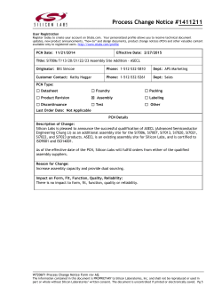
Si 8 0 x x - EVB Si80 XX T H R E E TO S I X CHANNEL D IGITAL I SOLATOR E VALUATION B OA RD U SER ’ S G UIDE 1. Introduction The Si80xx evaluation kit allows designers to evaluate Silicon Lab's family of low-power digital isolators. These are CMOS devices offering substantial data rate, propagation delay, power, size, reliability, and external BOM advantages over legacy isolation technologies. The operating parameters of these products remain stable across wide temperature ranges and throughout device service life for ease of design and highly uniform performance. All device versions have Schmitt trigger inputs for high noise immunity and only require VDD bypass capacitors. Data rates up to 10 Mbps are supported, and all devices achieve propagation delays of less than 65 ns. Enable inputs provide a single point control for enabling and disabling output drive. Ordering options include a choice of 1kVRMS isolation ratings. For more information, refer to the Si80xx family data sheets. This evaluation kit consists of an evaluation board featuring the QSOP-16 package. Note that the other packages are not available at this time. 1.1. Kit Contents The Si80xx Evaluation Kit contains the following items: Si80xx Si80xx Si8065 based evaluation board as shown in Figures 1. Digital isolator (installed on the evaluation board) (QSOP-16) Figure 1. Si80xx Evaluation Board Overview Rev. 0.1 3/14 Copyright © 2014 by Silicon Laboratories Si80xx-EVB Si80xx-EVB 2. Required Equipment The following items are required to demonstrate the evaluation board: 1 digital multimeter multimeter test leads (red and black) 1 oscilloscope (Tektronix TDS 2024B or equivalent) 1 BNC splitter 4 coaxial cables 2 dc power supply (HP6024A, 30 V dc, 0–100 mA or equivalent) 2 BNC to clip converters (red and black) 4 Banana to clip wires (2 red and 2 black) 1 function generator (Agilent 33220A, 20 MHz or equivalent) Si80xx Evaluation Board (board under test) Si80xx Digital Isolator Input Evaluation Board User's Guide (this document) 2 2 Rev. 0.1 Si80xx-EVB 3. Hardware Overview and Demo Figure 2 illustrates the connection diagram used to demonstrate the Si80xx-EVB. This demo transmits a 500 kHz (5 V peak, 50 percent duty cycle) square wave through the isolator to its output. In this example, VDD1 and VDD2 are powered by 5 V supplies. Figure 3 shows a scope shot of CH1 (input) and CH2 (output). Note that if a user wants to evaluate a digital isolator other than the ones pre-populated, this can be accomplished by removing the installed device and replacing it with the desired footprint-compatible isolator device. 5 V Supply 5 V Supply Si8065 EVB Signal Generator Signal Input 500 kHz, 5 Vpk Square Wave VDD1 A1 GND1 Oscilloscope VDD2 B1 GND2 Ch1 Ch2 Figure 2. Summary Diagram and Demo Setup Figure 3. Oscilloscope Display of Input and Output Rev. 0.1 3 Si80xx-EVB 3.1. DC Supply Configuration To run the demo, follow the instructions below. Review Figure 2 and Figure 5 if necessary. 1. Turn OFF the dc power supply and ensure that the output voltage is set to its lowest output voltage. 2. Connect the banana ends of the black and red banana-to-clip terminated wires to the outputs of both dc supplies. 3. For the input side of the Si80xx-EVB, connect the clip end of the red banana-to-clip terminated wire to VDD1 and the clip end of the black wire to GND1. 4. Similarly, for the output side of the EVB, the red wire goes to VDD2 and the black wire goes to GND2. 5. Turn ON the dc power supply and adjust both dc power supplies to provide 5 V on their outputs. 6. Ensure that the current draw is less than 25 mA. If it is larger, this indicates that either the board or Si80xx has been damaged or the supply is connected backwards. 3.2. Wave Form Generator 1. Turn ON the arbitrary waveform generator with the output disengaged. 2. Adjust its output to provide a 500 kHz, 0 to 5 V peak square wave (50 percent duty cycle) to its output. 3. Connect one end of the first coaxial cable to the output of the signal generator. 4. Connect the BNC splitter to the other end of the first coaxial cable. 5. From the BNC splitter, connect the second coaxial cable to CH1 of the scope. CH1 will display the input to the EVB. 6. Connect the third coaxial cable to the BNC splitter, and connect a BNC-to-clip converter to the end of this coaxial cable. 7. From here, connect the clip end of the BNC-to-clip converter to the Si80xx-EVB’s A1 (red wire here) and GND1 (black wire here). 8. Connect one end of the fourth coaxial cable to a BNC-to-clip converter (note that a scope probe can be used here instead). 9. From here, connect the clip end of the BNC-to-clip converter to the Si80xx-EVB’s B1 (red wire here) and GND2 (black wire here). 10. Connect the other end of the fourth coaxial cable to CH2 of the oscilloscope. CH2 will display the output of the EVB. 11. Engage the output of the waveform generator. 3.3. Oscilloscope Setup 1. Turn ON the oscilloscope. 2. Set the scope to Trigger on CH1 and adjust the trigger level to 1 V minimum. 3. Set CH1and CH2 to 2 V per division. 4. Adjust the seconds/division setting to 400 ns/division. 5. Adjust the level indicator for all channels to properly view each channel as shown in Figure 3. A 500 kHz square wave should display on Channel 1 of the scope for the input and a 5 V delayed version of this square wave should display the output on Channel 2, as shown in Figure 3. This concludes the basic demo. 4 Rev. 0.1 Si80xx-EVB 4. Hardware and Overview Setup The board is designed to be powered from two separate supplies VDD1, VDD2 that can be independently varied from 3.15 to 5.5 V. Figure 4 shows a silkscreen overview of the board and Figure 5 shows the board schematic. The power and jumper connection descriptions are summarized here: J1/3/5 Stake headers used to power and connect to the digital isolator’s Side1 pins. J2/4/6 Stake headers used to power and connect to the digital isolator’s Side 2 pins. TP1/2/3/4 Test Points that can also be used to provide VDD and GND. Figure 4. Si80xx DIP8 Evaluation Board Silkscreen Rev. 0.1 5 Si80xx-EVB 5. Si80xx Evaluation Board Schematics U1 DC_VDD1 DC_VDD2 1 TP1 J1 C1 1uF 1 2 3 4 5 6 7 8 C2 0.1uF TP3 2 3 4 5 6 HEADER 1x8 7 8 1 16 2 15 3 14 4 13 5 12 6 11 7 10 8 9 16 TP2 J2 15 14 13 12 1 2 3 4 5 6 7 8 C3 0.1uF C4 1uF TP4 11 HEADER 1x8 10 9 SOIC16WB U2 DC_VDD1 1 J3 C5 1uF 1 2 3 4 5 6 7 8 C6 0.1uF 2 3 4 5 6 HEADER 1x8 7 8 DC_VDD2 1 16 2 15 3 14 4 13 5 12 6 11 7 10 8 9 16 J4 15 14 13 12 1 2 3 4 5 6 7 8 C7 0.1uF C8 1uF 11 HEADER 1x8 10 9 SOIC16NB U3 DC_VDD1 1 J5 C9 1uF 1 2 3 4 5 6 7 8 C10 0.1uF 2 3 4 5 6 HEADER 1x8 7 8 DC_VDD2 1 16 2 15 3 14 4 13 5 12 6 11 7 10 8 9 16 J6 15 14 13 12 1 2 3 4 5 6 7 8 C11 0.1uF 11 HEADER 1x8 10 9 QSOP16 SF1 SF2 SF3 SF4 Figure 5. Si80xx Evaluation Board Schematic 6 Rev. 0.1 C12 1uF Si80xx-EVB 6. Bill of Materials Table 1. Si80xx Evaluation Board Bill of Materials Item Qty Ref Part # Supplier Description Value 1 6 C1, C4, C5, C8, C9, C12 C0603X5R250-105K Venkel CAP, 1 µF, 25 V, ±10%, X5R, 0603 1 µF 2 6 C2, C3, C6, C7, C10, C11 C0805X7R101-104K Venkel CAP, 0.1 µF, 100 V, ±10%, X7R, 0805 0.1 µF 3 6 J1, J2, J3, J4, J5, J6 TSW-108-07-T-S Samtec Header, 1x8, 0.1in pitch, tin plated HEADER 1x8 4 4 SF1, SF2, SF3, SF4 SJ61A6 3M HDW, Bumpon cylindrical 312X.215 BLK Bumper 5 4 TP1, TP2, TP3, TP4 151-201-RC Kobiconn Testpoint, White, PTH White 6 1 U1 Si8065AD-B-IS (not installed) Silicon Labs IC, three to six-channel digital SOIC16WB isolators, SOIC16WB 7 1 U2 Si8065AC-B-IS1 (not installed) Silicon Labs IC, three to six-channel digital isolators, SOIC16NB 8 1 U3 Si8065AA-B-IU Silicon Labs Rev. 0.1 IC, isolator, 6 I/O, QSOP16 SOIC16NB QSOP16 7 Si80xx-EVB 7. Ordering Guide Table 2. Si80xx Evaluation Board Ordering Guide Ordering Part Number (OPN) Si80xx-KIT 8 Description Si80xx Isolator Evaluation Board Kit Rev. 0.1 Si80xx-EVB CONTACT INFORMATION Silicon Laboratories Inc. 400 West Cesar Chavez Austin, TX 78701 Tel: 1+(512) 416-8500 Fax: 1+(512) 416-9669 Toll Free: 1+(877) 444-3032 Please visit the Silicon Labs Technical Support web page: https://www.silabs.com/support/pages/contacttechnicalsupport.aspx and register to submit a technical support request. Patent Notice Silicon Labs invests in research and development to help our customers differentiate in the market with innovative low-power, small size, analogintensive mixed-signal solutions. Silicon Labs' extensive patent portfolio is a testament to our unique approach and world-class engineering team. The information in this document is believed to be accurate in all respects at the time of publication but is subject to change without notice. Silicon Laboratories assumes no responsibility for errors and omissions, and disclaims responsibility for any consequences resulting from the use of information included herein. Additionally, Silicon Laboratories assumes no responsibility for the functioning of undescribed features or parameters. Silicon Laboratories reserves the right to make changes without further notice. Silicon Laboratories makes no warranty, representation or guarantee regarding the suitability of its products for any particular purpose, nor does Silicon Laboratories assume any liability arising out of the application or use of any product or circuit, and specifically disclaims any and all liability, including without limitation consequential or incidental damages. Silicon Laboratories products are not designed, intended, or authorized for use in applications intended to support or sustain life, or for any other application in which the failure of the Silicon Laboratories product could create a situation where personal injury or death may occur. Should Buyer purchase or use Silicon Laboratories products for any such unintended or unauthorized application, Buyer shall indemnify and hold Silicon Laboratories harmless against all claims and damages. Silicon Laboratories and Silicon Labs are trademarks of Silicon Laboratories Inc. Other products or brandnames mentioned herein are trademarks or registered trademarks of their respective holders. Rev. 0.1 9
© Copyright 2026 ExpyDoc