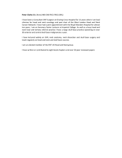
Jan. 31, 1939.
N E GEE
2,145,542
FLEXIBLE DRIVE
Filed 001;. 22, 1956
'
2 Sheets-Sheet 1
Jan. 31, 1939.
N, E“ GEE
.
2,145,542
FLEXIBLE DRIVE '
Filed Oct. ‘22, 1956
2 Sheets-Sheet 2
\M
ii ~
H?_
54,54?
5
6'
25
E
-
g,
f?”
20
PL 11
PL
17
PL
W1 TNESSES:
31%;
@
'
s I N VEN TOR .
" Mrmam/ E @w,
Patented Jan. 31, 1939
UNITED STATES PATENT
2,145,542
FLEXIBLE muvn
Application
Norman
October
E. 22,
Gee,1936,
Altoona,
SerialPa.
No. 107,022
.
'
6 Claims.
(c1. (st-2t)
This invention relates to a ?exible drive and
to electric locomotives which have the main driv
ing motors positioned on the main frame of the
locomotive, and the torque of the motors de
llvered
through ?exible means to the driving
ing wheels.
wheels. In thus applying this new ?exible driv
A primary object of the invention is to provide ing gear to a modern electric locomotive, no
a ?exible drive which is characterized by sim- , change is contemplated in the main driving
plicity of construction, low cost of manuiacture, motors, main frame of the locomotive, quill, or
and ease of assembly and which is nevertheless
10 durable and capable of e?icient operation over gears that transfer the motor torque to the
driving unit, but the change in design is con‘ 10
a long period of time.
?ned to the character of the connecting unit
Another object ,of the invention is to provide disposed between the driving gear and the driv
a drive ‘unit, used for ?exibly connecting the ing wheels.
,r
~
'
driving and driven members, which comprises
With reference to Figs. 1' and II of the draw-\
counterpart rubber'elements disposed in axial ings, there is shown a locomotive driving wheel 15
has special application to quill drives of the type
used on electric locomotives for transmitting the
torque of a driving motor-to the locomotive driv
alignment and with their free ends engaging I designated by the numeral a, which is mounted
surfaces on the wheel to be driven.
5‘
A further object of the invention is to provide
means for holding such resilient drive units
.230 within an opening in the wheel to be driven,
together with means for adjusting ‘the position
of said units, as Wear occurs to compensate for
such wear.
-
Other objects and advantages characteristic
25 of my invention will become more fully apparent
from the description hereinafter set forth of one
upon an axle t. Surrounding the axle t there is
a quill it, upon which is mounted a gear center
it, the gearcenter having gears it at its pe
riphery and being housed within a gear case it.
It may be assumed that the quill it is driven by
an electric motor. Su?lcient clearance is pro
vided between ‘the axle t and quill it to allow
for considerable relative movement between these
parts and thus to take care of spring de?ection.
The gear center it is further provided with a
embodiment or example of the invention, together plurality of raised machined faces it; upon each _
with a modi?cation thereof, having reference to of which a driving arm it is positioned and held
the accompanying drawings. Of the drawings: ' securely on the gear center by a plurality of
30
Fig, I represents a fragmentary side elevation machined and ?tted bolts it.
.
of my improved ?exible drive applied to a loco
motive driving gear center, with certain parts
shown in cross section, and illustrates the man- >
ner in which the resilient drive units coact with
‘ parts of the driving wheel of the locomotive.
Fig. 11 represents a cross section of the same,
to
taken as indicated by the lines 11-11 of Fig. I.
Fig, III represents a fragmentary View some
what similar to Fig. I, but showing an alterna
ti 2 method of applying the resilient drive units
to the arm carried on the driving gear center.
Fig. IV represents a view showing the same
?ange t at one end thereof and arcuate slots ‘i
at the opposite end. The connecting units for
transmitting the torque of the gear center it to 35
the locomotive driving wheel t are comprehen
sively designated at ll. Each such unit consists
of a pair of counterpart resilient moulded rubber
pieces ii of substantially plug-shaped‘ formation.
Each rubber element t has a cylindrical base
portion it and a cylindrical cantilever necklpor
tion it through which the driving load is trans
mitted to pads it positioned adjacent to the
openings between the spokes 28 of the driving
for wear.
'
'
’
wheels 8. The rubber elements t of each pair are
Fig. V represents a perspective .view of one of spaced back to back and are adapted to‘ abut
the locking rings used for maintaining‘the re against each other as clearly; shown in Fig. I of
silient drive units in ?xed position within their the drawings. On the base’ it of each rubber
supporting holders; and,
I
~
)
element ii, there “is a circular metal disc at to
Fig. VI represents an enlarged cross sectional which the base is yiucaniaed along thesurface
view, taken as indicated by the lines VI--VI of it, while on the opposite?suriace it of this disc
Fig. II, showing the manner in which the locking the neck portion id is also vulcanized. The rub?
ring is a?xed to the holder.
ber elements t of the drive units ll, when in
This invention, although it may be applied to operative position on a locomotive, are in align
various types of drives, is particularly applicable ment
with each other with their‘ axes disposed
parts illustrated in Fig. III, but with the spacing
rings moved to a di?erent position to compensate
at
Each di'iving arm at includesa cylindrically
shaped holder 5, with aninwardly projecting
2,145,542
2
substantially at right angles to the pads 20. The
free elongated ends of each pair of rubber ele
ments 4 engage the oppositely disposed pads 29
at each side of the opening within which the
drive unit is positioned. In an obvious manner,
when the motor and the gear center || rotate
in one direction the drive units I‘! will engage
the pads 20 at one side of the openings between
the spokes 2|, whereas when the motor and gear
10 center revolve in the opposite direction the drive
units will engage the pads at the opposite side of
the opening between the spokes.
‘
rings 26 and locking rings 3|, thus providing a
housing around the rubber element 4 separated
from the element 4 by an annular space. This ,
annular space is provided for two primary rea
sons: firstly, because it permits the elongated‘
neck portions l9 of the rubber elements 4 to act
as cantilevers, thus providing for the requisite
flexibility under bending or shearing stresses
to permit the locomotive driving wheel 8 to fol
low uneven track while “the locomotiveirame to
which the gear center I4 is indirectly attached
virtually bridges over the unevenness of the
In the assembly of this new driving unit, a
holding ring 26 is ?rst placed in position within
15 the holder 5 with its ledge 21 engaging the in
wardly projecting?ange 6. Then the Womb
ber elements 4 are positioned with their bases IS
in proximate relation to each other within the
holder 5, and their neck portions |9 protruding
20 toward the pads 29 on the wheel spokes 2|. The
track; and secondly,. because when‘ starting
heavy trains the drive unit |'| tends to recede
and enlarge, and in its enlarged form the neck
portions |9\of the rubber elements 4 substantial
ly ?ll the space within the holder 5, thus support
ing the rubber elements and decreasing the can
tilever action which results in an increase of the
life of the drive unit.
-
‘
rubber elements 4 being thus positioned within
_ It will be apparent that the resilient drive
3| the projecting lugs 32 are aligned in registry
ing many advantages over the drives now in com
20"
herein described and illustrated are of very
the holder 5, a locking ring 9| is inserted. De _units
and inexpensive construction, ‘and that
tails of the locking ring 3| are shown clearly in simple
the
rubber
elementsmay be applied, adjusted or
the perspective view of Fig‘. V. The ring has replaced very
easily as occasion demands.’ The 26
thereon a-number of radially projecting lugs 32
which are adaptedto be received in the arcuate construction is none'the less dependable and ef
slots 1 of the holder 5. To insert the locking ring ?cient and serves to produce a ?exible drive hav
with the slots 1. The locking ring 3| is then
30 pressed inwardly within the holder 5 and ro
tated until the projections 32 are in positions
behind the ledge 34 of the holder 5. The locking
ring 3| being thus placed in position is securely
locked therein by means of a number of tap bolts
"as
4.0
35 which engage threaded openings 36 in the
holder 5 and openings 31 in the locking ring 3|,
as shown most clearly in Fig. VI. vThe tap bolts
35 are held against rotation after their insertion
by means of a wire 38 applied in the manner
shown most clearly in Fig. I, or by any other
suitable means- With the parts thus assembled
within the holder 5,‘ the entire assembly associ
- ated driving arm I5 can be readily applied to the
‘gear center H by means of the bolts I6 after
mon use.
'
_ Throughout this speci?cation the wheels of 80
the locomotive which engage the rails have been
referred to as the “driving wheels”, because they
serve to drive the locomotive, but~such wheels
are in reality the driven members of the combi
nation of elements described andillustrated here 35
in, and they are referred to as such in the claims
which follow.
’
‘
v‘
While I have described an example of my in- .
vention, together with a modi?cation thereof, it
will be apparent to those skilled in the art that 40
various other changes and modi?cations may be
made‘without departing from the spirit or scope
of the invention as de?ned in the annexed claims,
and it will also be apparent that the invention
' is not con?ned in its‘ application to use with a 45
.45 which the unit is in readiness for operation?
In Fig. 111, there isshown a modi?ed form of quill drive for electric locomotives.
Having thus described my invention, I claim:
the invention, in which no change is made in ,
1. A ?exible drive cgmprising a‘ holder, a driv
the construction of the arm l5 and its cylindrical
ing unit formed of av resilient material and hav
holder 5, and no change is made in the construc
tion of the rubber elements 4; but a'pl'uraiity of - ing a base portion and a neck portion, said base 60
50 rings are interposed in surrounding relation to portion being mounted in said holder with said
the rubber elements 4. More speci?cally in this neck portion projecting therefrom, the diameter
example, base rings 90 are interposed adjacent of said neck portion being substantially less than
to the disc portions 22 of the rubber elements 4, the internal diameter. of the portion of said
.
55' and additional rings 29, serving as spacing rings,
. are placed between the base rings 30 and the
holding ring 29 at one end of the unit and be
tween the base ring 30 and the locking ring 9| at
the other end of the unit. ,When this construc
tion is utilized, as wear takes ‘place the rubber
elements 4 may be readjusted. to compensate for
such wear by changing the position of one or
more of the spacing rings 29 to suit the existing
condition. Such an adjustment is illustrated 'in
Fig. IV, wherein one of the, spacing rings 29 has ‘
been moved to a position intermediate the bases
l8 of the‘rubber elements 4. when the spacing
rings 29 are ,thus shifted, it is desirable to uti
lize solid discs 39 which areplaced between the
holder extending around said neck portion, and
a-driven member with which said driving unit
contacts in driving.
2. A ?exible drive comprising a holder, a driv
‘ing unit formed of a resilient material and hav
ing abase portion and a neck portion of less 60
diameterv than‘ said base portion, said base portion
- being mounted in‘said holder, a holding ring at
tached to said holder and having an internal di
ameter which is substantially less than that of
said base portion but substantially greater than
that of said neck portion whereby said driving
unit may ?ex fully within de?ned limits, ‘and a
65
driven unit with which said driving unit con
tacts in driving.’
I
_
3. The invention of claim 2, characterized fur 70
70, base sections IQ of the rubber elements 4 and the . ther
by the fact that said base portion has a stiff
spacing rings 29 in order to properly maintain
the shape of the rubber elements.
‘ In the examples illustrated above, it will be
noted that the neck portions I901 the rubber
elements 4 do not ?t snugly within the holding
disc-like outer face to which said neck portion
is joined integrally.
4. A ?exible drive comprising a holder, a driv
ing unit mounted in said holder and having a 76.
3
base portion and a neck portion both formed of
resilient material, said base portion having a
non-resilient disc-like face on which said neck
portion is mounted integrally, a holding ring se
cured to said holder and extending around said
neck portion, said ring having an internal di
ameter substantially greater than that of said
neck portion but substantially less than that of
said base portion, and a driven unit with which
10 said drive unit contacts in driving.
5. A ?exible drive unit comprising a holder, a
pair of drive units made of a resilient material
and each consisting of a base portion and a neck
portion, said units being mounted in said holder
a
with their base portions contacting, holding rings
attached to said holder and extending around
said neck portions, each said vholding ring having
an internal diameter greater than-that of said
neck portions and less than ‘that of said base
portion, and driven units with which said drive 5
units contact in driving.
6. The invention of claim 5 characterized fur
ther by the fact that each said base portion has
an outer disc-like face made of a non-resilient 10
material on which each said neck portion is in
tegrally mounted.
-
NORMAN E. GEE.
© Copyright 2026 ExpyDoc