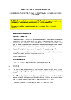
1
High Temperature Application Guide
PID versus GSS Sensors
Kanomax offers three different types of sensor for measurement of volatile organic compounds (VOCs): PID, GSS VOC
and GSS NMHC. These sensors have been designed to respond to a broad range of VOCs although they each display a
unique sensitivity to certain VOCs or classes of hydrocarbon, (see Table). However, the range of sensitivity of each sensor
substantively overlaps with the others (see Diagram).
Sensor
Selectivity
Ambient gases
PID
Sensitive to wide range of gases but insensitive to some Aromatic hydrocarbons, fuels
common gases eg propane, formaldehyde, alcohols
GSS NMHC
Most sensitive to hydrocarbons
Aromatic hydrocarbons, fuels, olefins
GSS VOC
Sensitive to wide range of gases
Hydrocarbons, alcohols, formaldehyde
Copyright © 2014 by Kanomax USA, Inc.
2
High Temperature Application Guide
PID Gas Response Times
The PID sensors offered by Kanomax have a different response to a variety of gases as shown in the table below. The
Response Factor (RF) provides a sensitivity measure relative to isobutylene (RF=1). The PID sensor is more sensitive to
compounds with lower RF values. Compounds not listed may also be detected by PID - please contact us for more information.
PID Sensor Specifications:
Calibrated Maximum
Lowest
Range (ppm) Exposure Detection
(ppm)
Limit
Accuracy of
Calibration
Resolution Response Sampling
(ppm)
Time (T90) Method
Operational Range
Temp.
RH
non condensing
0 - 20
100
0.01 ppm
<±0.02ppm + 10%
0.01
30s
Fan
0 to 40°C
0 to 95%
0-1000
1000
0.1 ppm
<±0.2ppm + 10%
0.1
30s
Fan
0 to 40°C
0 to 95%
Response Factors:
••
••
The default sensor concentration reading is in units of ppm of Isobutylene.
••
For example, the PID sensor head is calibrated against Isobutylene and is being used to measure the concentration of heptane. The reading in ppm of Isobutylene is 10ppm. Therefore the concentration of heptane is 10
ppm x 2.5 = 25 ppm.
••
The VOC sensor can also be used to qualitatively indicate the total VOC level. The units of measurement are ppm
Isobutylene equivalent.
The user can convert this into ppm of another gas by multiplying the reading by the response factor (RF) listed
below.
Compound
Response
Factor (RF)*
Compound
Response
Factor (RF)*
1,2,3-trimethylbenzene
0.49
acetophenone
0.59
1,2,4-trimethylbenzene
0.43
acrolein
3.9
1,2-dibromoethane
11.7
allyl alcohol
2.5
1,2-dichlorobenzene
0.5
ammonia
9.4
1,3,5-trimethylbenzene
0.34
amylacetate
3.5
1,4-dioxane
1.4
arsine
2.6
1-butanol
3.4
benzene
0.53
1-methoxy-2-propanol
1.4
bromoform
2.3
1-propanol
5.7
bromomethane
1.8
2-butoxyethanol
1.3
butadiene
0.69
2-methoxyethanol
2.5
butyl acetate
2.4
2-pentanone
0.78
carbon disulfide
1.2
2-picoline
0.57
chlorobenzene
0.4
3-picoline
0.9
cumene (isopropylbenzene)
0.54
4-hydroxy-4-methyl-2-pentanone
0.55
cyclohexane
1.5
acetaldehyde
10.8
cyclohexanone
0.82
acetic acid
11
decane
1.6
acetone
1.2
diethylamine
1.0
* A smaller RF means the PID is more sensitive to the compound
Copyright © 2014 by Kanomax USA, Inc.
PID Gas Response Times cont.
Compound
Response
Factor (RF)*
Compound
Response
Factor (RF)*
dimethoxymethane
11.3
methyl tert-butyl ether
0.86
dimethyl disulfide
0.3
ether
0.86
diesel fuel #1
0.9
methylamine
1.2
diesel fuel #2
0.75
methylbenzil alcohol
0.8
epichlorhydrin
7.6
m-xylene
0.53
ethanol
10.0
naphtalene
0.37
ethyl acetate
4.2
n,n-dimethylacetamide
0.73
ethyl acetoacetate
0.9
n,n-dimethylformamide
0.8
ethyl acrylate
2.3
n-hexane
4.5
diethyl ether
1.2
nitric oxide
7.2
ethyl mercaptan
0.6
n-nonane
1.6
ethylbenzene
0.51
n-pentane
9.7
ethylene
10.1
n-propyl acetate
3.1
gasoline
1.1
octane
2.2
heptane
2.5
o-xylene
0.54
hydrazine
2.6
phenol
1.0
hydrogen sulfide
3.2
phosphine
2.8
isoamyl acetate
1.8
pinene, alpha
0.4
isobutanol
4.7
pinene, beta
0.4
isobutyl acetate
2.6
propylene
1.3
isobutylene
1.0
propylene oxide
6.5
isooctane
1.3
p-xylene
0.5
isopentane
8.0
pyridine
0.79
isophorone
0.74
quinoline
0.72
isoprene (2-methyl-1,3-butadiene)
0.6
styrene
0.4
isopropanol
5.6
tert-butyl alcohol
3.4
isopropyl acetate
2.6
tert-butyl mercaptan
0.55
isopropyl ether
0.8
tert-butylamine
0.71
isopropylamine
0.9
tetrachloroethylene
0.56
Jet A Fuel
0.4
tetrahydrofuran
1.6
JP-5 Fuel
0.48
thiophene
0.47
JP-8 Fuel
0.48
toluene
0.53
mesityl oxide
0.47
trans-1,2-Dichloroethene
0.45
methyl acetate
7.0
trichloroethylene
0.5
methyl acetoacetate
1.1
trimethylamine
0.83
methyl acrylate
3.4
turpentine crude sulfite
1.0
methyl benzoate
0.93
turpentine pure gum
0.45
methyl ethyl ketone
0.9
vinyl acetate
1.3
methyl isobutyl ketone
1.1
vinyl bromide
0.4
ketone
1.1
vinyl chloride
1.8
methyl mercaptan
0.6
vinylcyclohexane (VCH)
0.54
methyl methacrylate
1.5
vinylidene chloride (1,1-DCE)
0.8
* A smaller RF means the PID is more sensitive to the compound
Copyright © 2014 by Kanomax USA, Inc.
4
High Temperature Application Guide
GSS Technology Background
Gas Sensitive Semiconductor (GSS) technology is a combination of smart measurement techniques and
mixed metal oxide semiconductor sensors that exhibit an electrical resistance change in the presence of a
target gas.
This resistance change is caused by a loss or a gain of surface electrons as a result of adsorbed oxygen reacting with the target gas. If
the oxide is an n-type, there is either a donation (reducing gas) or subtraction (oxidising gas) of electrons from the conduction band.
The result is that n-type oxides increase their resistance when oxidising gases such as NO2 and O3 are present while reducing gases
such as CO and hydrocarbons lead to a reduction in resistance. The converse is true for p-type oxides where electron exchange due
to gas interaction leads either to a rise (oxidising gas) or a reduction (reducing gas) in electron holes in the valence band. This then
translates into corresponding changes in electrical resistance. Quantitative response from the sensor is possible as the magnitude
of change in electrical resistance is a direct measure of the concentration of the target gas present.
Since the surface reaction causes the change in electrical resistance in the sensing oxide, maximising the surface area intensifies
the response to gas. To take advantage of this effect, commercial gas sensors consist of highly porous oxide layers, which are either
printed or deposited onto alumina chips. The electrodes are usually co-planar and located at the oxide/chip interface (see diagram
below). A heater track is also applied to the chip to ensure the sensor runs “hot” which minimises interference from humidity and increases the speed of response. The microstructure of the oxide, its thickness and its running temperature are optimised to improve
selectivity. Catalytic additives, protective coatings and activated-carbon filters are also applied to enhance selectivity.
Sensor
Sensor PC Board
Sensing layer
Active Sampling Fan
On-board Processor
Alumina substrate
Gold electrodes
Diagram of typical sensor formulation
Typical sensor head & key components
The range of GSS sensor-based products offered by Kanomax has been designed to provide near scientific accuracy, high reliability
and functionality at an affordable price. Aeroqual’s concept of fully interchangeable sensor heads eliminates the need for field calibration and provides users with unique application focused solutions.
Kanomax USA, Inc.
P.O. Box 372
219 US Hwy 206, Andover, NJ 07821 USA
TEL: 800-247-8887 (USA) * 973-786-6386
FAX: 973-786-7586
E-mail: [email protected]
URL: www.kanomax-usa.com
Copyright © 2014 by Kanomax USA, Inc.
© Copyright 2026 ExpyDoc