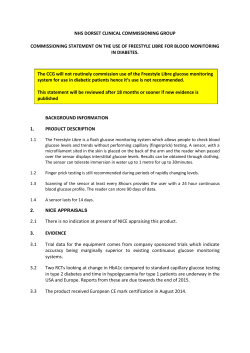
SureCross Wireless Q45 Sensor - Remote
Device
Datasheet
SureCross® Wireless Q45 Sensors combine the best of Banner’s flexible Q45 sensor family with its reliable, field-proven,
SureCross wireless architecture to solve new classes of applications limited only by the user’s imagination. Containing a
variety of sensor models, a radio, and internal battery supply, this product line is truly plug and play.
The Remote Device model is designed to interface with isolated dry contacts
(pushbuttons), sourcing outputs, or Namur inductive proximity sensors.
Although these models support two dry contact inputs, the default Gateway I/O
mapping configuration of the Banner Q45 wireless system supports one dry contact
input. To map the second dry contact input on the Q45, use the Gateway's DIP
switches to map the I/O. See the Gateway's datasheet for details.
Important: Because these sensors run on very low battery power, the contact
wetting voltage is 3.3 volts. High voltage contacts are not designed to reliably switch
these low voltages. Use a contact rated for operation at 3.3 volts.
Available Models
•
•
DX80N2Q45RD-QPF-0.5 with an 18 inch female pigtail
DX80N2Q45RD with a female connector embedded in the front
WARNING: Not To Be Used for Personnel Protection
Figure 1. Model DX80N2Q45RD-QPF-0.5
Never use this device as a sensing device for personnel
protection. Doing so could lead to serious injury or death.
This device does not include the self-checking redundant
circuitry necessary to allow its use in personnel safety
applications. A sensor failure or malfunction can cause either an
energized or de-energized sensor output condition.
Figure 2. Model DX80N2Q45RD
Storage Mode for the Wireless Q45 Sensors
While in storage mode, the Wireless Q45 Sensor's radio does not operate. All Wireless Q45 Sensors ship from the factory
in storage mode to conserve the battery. To wake the device, press and hold the button for five seconds. To put any
Wireless Q45 Sensor into storage mode, press and hold the button for five seconds. The Wireless Q45 Sensor is in storage
mode when the LEDs stop blinking.
Button, LEDs, and DIP Switches
5
1
2
Original Document
162663 Rev. D
3
4
1
Button
2
Green LED (flashing) indicates a good radio link with the Gateway.
3
Red LED (flashing) indicates a radio link error with the Gateway.
4
Amber LED indicates when input 1 is active. The LED is active at power
up and disabled after 15 minutes to conserve power. To enable the LED
for another 15 minutes, press button once. To disable the LED, press the
button 5 times.
5
DIP Switches
4 November 2014
162663
SureCross Wireless Q45 Sensor - Remote Device
DIP Switches for Dry Contact Input Mode (DIP Switch 1 OFF)
After making any changes to any DIP switch position, reboot the Wireless Q45 Sensor by triple-clicking the button, waiting
a second, then double-clicking the button. You may also reboot the device by removing the battery pack, then re-installing
it.
As shown in the image above, the DIP switches are in the OFF position. To turn a DIP switch on, push the switch toward
the battery pack. DIP switches one through four are numbered from left to right as shown above.
Description
DIP Switches
1
Dry contact input mode
2
3
4
OFF *
3.3 V contact wetting voltage
OFF *
5.5 V contact wetting voltage
ON
Two dry contact inputs
OFF *
One dry contact input
ON
62.5 millisecond sample rate
OFF *
250 millisecond sample rate
ON
* Default position (as shown above)
DIP Switches for Namur Input Mode (DIP Switch 1 ON)
After making any changes to any DIP switch position, reboot the Wireless Q45 Sensor by triple-clicking the button, waiting
a second, then double-clicking the button. You may also reboot the device by removing the battery pack, then re-installing
it.
As shown in the image above, the DIP switches are in the OFF position. To turn a DIP switch on, push the switch toward
the battery pack. DIP switches one through four are numbered from left to right as shown above.
DIP Switches
Description
1
3
4
2 millisecond warmup time, 62.5 ms sample rate
OFF *
OFF *
2 millisecond warmup time, 250 ms sample rate
OFF
ON
5 millisecond warmup time, 125 ms sample rate
ON
OFF
5 millisecond warmup time, 500 ms sample rate
ON
ON
Namur input mode
2
ON
5.5 V sensor voltage
OFF *
8.2 V sensor voltage
ON
To use with Turck's Bi2-M12-Y1X-H1141, Bi5-M18-Y1X-H1141 Namur proximity sensor, set DIP switch 1 to ON and DIP
switches 2 through 4 to OFF.
To use with Turck's Bi10-M30-Y1X-H1141 Namur proximity sensor, set DIP switch 1 and 3 to ON and DIP switches 2 and 4
to OFF.
Use cable MQDEC-406SS (male to female cable) to connect the Namur sensors to the Wireless Q45 Sensor - Remote
Device model's interface.
2
www.bannerengineering.com - Tel: +1-763-544-3164
P/N 162663 Rev. D
SureCross Wireless Q45 Sensor - Remote Device
Wiring
5-pin M12/Euro-style Female Connection
Pin No. Wire Color
1
Brown
VOut
2
White
Discrete IN 2 or Namur IN 1
3
Blue
dc common (GND)
3
4
Black
Discrete IN 1
5
5
Gray
-
2
1
4
Wireless Q45 Sensor
Wiring for Dry Contact Mode
Wiring for Namur Mode
Sourcing
dry contacts
1
VOut
4
Discrete IN 1
4
2
Discrete IN 2
2
Namur IN 1
3
dc common/GND
3
dc common/GND
1
VOut
Namur
Prox Sensor
Wiring for Externally Powered Sourcing Sensors
1
VOut
4
Discrete IN 1
2
Discrete IN 2
Voltage at the discrete IN:
• 0 V to 1 V = OFF
• 2 V to 5 V = ON
• More than 6 V will damage the Q45 sensor's input
R
R
3
dc common/GND
24V
Internal resistance is 800 Ohms. To connect the Wireless
Q45 Sensor to a 24 V sourcing output, add a 3.0 KOhm to
5.6 KOhm external resistor in series to reduce the voltage
applied to the Q45 Sensor's discrete input to less than 6 V.
R = 3.0 to 5.6 KOhm at 24 V
Modbus Register Table
Modbus Holding Register
I/O
#
Gateway
Any Node
1
1
1 + (Node# × 16)
2
2
2 + (Node# × 16)
I/O Type
I/O Range
Holding Register
Representation
Min. Value
Max.
Value
Min.
(Dec.)
Max.
(Dec.)
Discrete IN 1 OR Namur
IN 1
0
1
0
1
Discrete IN 2
0
1
0
1
...
7
7
7 + (Node# × 16)
Reserved
8
8
8 + (Node# × 16)
Device Message
...
15
15
P/N 162663 Rev. D
15 + (Node# × 16)
Control Message
www.bannerengineering.com - Tel: +1-763-544-3164
3
SureCross Wireless Q45 Sensor - Remote Device
I/O
#
16
Modbus Holding Register
I/O Type
Gateway
Any Node
16
16 + (Node# × 16)
I/O Range
Min. Value
Max.
Value
Holding Register
Representation
Min.
(Dec.)
Max.
(Dec.)
Reserved
Replacing the Batteries
To replace the lithium "AA" cell battery, follow these steps.
As with all batteries, these are a fire, explosion, and severe burn hazard. Do not burn or expose them to high
temperatures. Do not recharge, crush, disassemble, or expose the contents to water. Properly dispose of used batteries
according to local regulations by taking it to a hazardous waste collection site, an e-waste disposal center, or other facility
qualified to accept lithium batteries.
1. Lift the plastic cover.
2. Slide the board containing the batteries out of the Q45 housing.
3. Remove the discharged batteries and replace with new batteries. Use
two 3.6 V AA lithium batteries, such as Xeno's XL-60F or equivalent.
4. Verify the battery’s positive and negative terminals align to the positive
and negative terminals of the battery holder mounted within the case.
Caution: There is a risk of explosion if the battery is replaced incorrectly.
5. Slide the board containing the new batteries back into the Q45 housing.
Replacement battery model number: BWA-BATT-006. For pricing and
availability, contact Banner Engineering.
Bind the Q45s to the Gateway and Assign the Node Address
Before beginning the binding procedure, apply power to all the devices.
1. Enter binding mode on the Gateway.
•
•
For -B2Q board modules, triple-click the button.
For -Q and -QC models, triple-click button 2.
On the board modules, the green and red LED flashes. On the -Q and -QC Gateway models, both LEDs flash red.
2. Assign the Q45 a Node address using the Gateway's rotary dials. Use the left rotary dial for the left digit and the right
rotary dial for the right digit. For example, to assign your Q45 to Node 01, set the left dial to 0 and the right dial to 1.
Valid Node addresses are 01 through 47.
3. Loosen the clamp plate on the top of the Wireless Q45 Sensor and lift the cover.
4. Enter binding mode on the Wireless Q45 Sensor by triple-clicking the button. For the opposed mode sensor, the button
is on the receiver.
The red and green LEDs flash alternately and the sensor searches for a Gateway in binding mode. After the Q45 is
bound, the LEDs stay solid momentarily, then they flash together four times. The Q45 exits binding mode.
5. Label the sensor with the Q45's Node address number and place the sticker on the Wireless Q45 Sensor.
6. Repeat steps 2 through 5 for as many Wireless Q45 Sensors as are needed for your network.
7. After binding all Wireless Q45 Sensors, exit binding mode on the Gateway.
•
•
For -B2Q board modules, double-click the button.
For -Q and -QC models, double-click button 2.
For Gateways with LCDs, after binding your Wireless Q45 Sensors to the Gateway, make note of the binding code
displayed under the Gateway's *DVCFG menu, XADR submenu on the LCD. Knowing the binding code prevents having to
re-bind all Q45s if your Gateway is ever replaced.
4
www.bannerengineering.com - Tel: +1-763-544-3164
P/N 162663 Rev. D
SureCross Wireless Q45 Sensor - Remote Device
Specifications
The following specifications refer to both the radio and the wireless sensor.
Radio Range
2.4 GHz: Up to 1000 m (3280 ft) with line of sight1
Typical Battery Life for One Dry Contact Input
Up to 3 years at a 62.5 ms sample rate or 250 ms sample rate.
Assumes an average of 10 seconds between changes of state and a
Gateway heartbeat setting of 30 seconds.
Radio Transmit Power
2.4 GHz: 65 mW EIRP
Typical Battery Life for Bi2 and Bi5 Namur Inputs
Up to 2 years at a 2 ms warmup time and 62.5 ms sample rate; 4
years at a 2 ms warmup time and 250 ms sample rate.
Assumes an average of 10 seconds between changes of state and a
Gateway heartbeat setting of 30 seconds.
2.4 GHz Compliance
FCC ID UE300DX80-2400 - This device complies with FCC Part 15,
Subpart C, 15.247
ETSI/EN: In accordance with EN 300 328: V1.7.1 (2006-05)
IC: 7044A-DX8024
Typical Battery Life for Bi10 Namur Inputs
Up to 2 years at a 5 ms warmup time and 125 ms sample rate; 4 years
at a 5 ms warmup time and 500 ms sample rate.
Assumes an average of 10 seconds between changes of state and a
Gateway heartbeat setting of 30 seconds.
Spread Spectrum Technology
FHSS (Frequency Hopping Spread Spectrum)
Externally Powered Sourcing Sensors
ON Condition: 2 V to 5 V
OFF Condition: Less than 1 V
Default Sample Rate
62.5 milliseconds (dry contact) or 125 milliseconds (Namur)
Construction
Molded reinforced thermoplastic polyester housing, oring-sealed
transparent Lexan® cover, molded acrylic lenses, and stainless steel
hardware. Q45s are designed to withstand 1200 psi washdown.
Report Rate
On Change of State
Operating Conditions
–40 °C to 70 °C (–40 °F to 158 °F); 90% relative humidity at 50 °C
(non-condensing)
Indicators
Red and green LEDs (radio function); amber LED indicates when input
1 is active
Environmental Rating
NEMA 6P, IEC IP67
DX80N2Q45RD Battery Life
3.5
3
250 ms Sample Rate
2.5
Battery Life (years)
62.5 ms Sample Rate
2
1.5
1
0.5
0
0
1
2
3
4
5
6
7
8
9
10
11
Change of State Interval (seconds)
Warnings
Violating Warnings. The manufacturer does not take responsibility for the violation of any warning listed in this
document. Make no modifications to this product; any modifications to this product not expressly approved by Banner
Engineering could void the user’s authority to operate the product. All specifications published in this document are
1 The actual radio range significantly decreases without line of sight. Always verify your wireless network's range by running a site survey.
P/N 162663 Rev. D
www.bannerengineering.com - Tel: +1-763-544-3164
5
SureCross Wireless Q45 Sensor - Remote Device
subject to change; Banner reserves the right to modify product specifications or update documentation at any time. For
the most recent version of any documentation, refer to: www.bannerengineering.com. © 2006-2014 Banner Engineering
Corp. All rights reserved.
Exporting SureCross Radios
Exporting SureCross Radios. It is our intent to fully comply with all national and regional regulations regarding radio
frequency emissions. Customers who want to re-export this product to a country other than that to which it was
sold must ensure the device is approved in the destination country. A list of approved countries appears in the
Radio Certifications section of the product manual. The SureCross wireless products were certified for use in these
countries using the antenna that ships with the product. When using other antennas, verify you are not exceeding the
transmit power levels allowed by local governing agencies. Consult with Banner Engineering Corp. if the destination
country is not on this list.
Banner Engineering Corp Limited Warranty
Banner Engineering Corp. warrants its products to be free from defects in material and workmanship for one year following
the date of shipment. Banner Engineering Corp. will repair or replace, free of charge, any product of its manufacture
which, at the time it is returned to the factory, is found to have been defective during the warranty period. This warranty
does not cover damage or liability for misuse, abuse, or the improper application or installation of the Banner product.
THIS LIMITED WARRANTY IS EXCLUSIVE AND IN LIEU OF ALL OTHER WARRANTIES WHETHER EXPRESS OR
IMPLIED (INCLUDING, WITHOUT LIMITATION, ANY WARRANTY OF MERCHANTABILITY OR FITNESS FOR A
PARTICULAR PURPOSE), AND WHETHER ARISING UNDER COURSE OF PERFORMANCE, COURSE OF DEALING OR
TRADE USAGE.
This Warranty is exclusive and limited to repair or, at the discretion of Banner Engineering Corp., replacement. IN NO
EVENT SHALL BANNER ENGINEERING CORP. BE LIABLE TO BUYER OR ANY OTHER PERSON OR ENTITY FOR
ANY EXTRA COSTS, EXPENSES, LOSSES, LOSS OF PROFITS, OR ANY INCIDENTAL, CONSEQUENTIAL OR
SPECIAL DAMAGES RESULTING FROM ANY PRODUCT DEFECT OR FROM THE USE OR INABILITY TO USE THE
PRODUCT, WHETHER ARISING IN CONTRACT OR WARRANTY, STATUTE, TORT, STRICT LIABILITY,
NEGLIGENCE, OR OTHERWISE.
Banner Engineering Corp. reserves the right to change, modify or improve the design of the product without assuming any
obligations or liabilities relating to any product previously manufactured by Banner Engineering Corp.
www.bannerengineering.com - Tel: +1-763-544-3164
© Copyright 2026 ExpyDoc