XVL Studio Basic Tutorial
For Version 12.1 and later
LATTICE TECHNOLOGY, INC.
Agenda
•
•
Overview
License Setup
Using Graphics Accelerator
File Operations
–
–
–
Sample Models
File Types
Importing/Exporting Files
•
•
Viewing Operations
–
–
•
Viewing operations
Display options
Authoring
–
–
–
–
–
–
–
–
–
Settings
–
–
•
•
Using the Assembly Tree
User Coordinate System
Moving parts
Adding notes
Measurement
Cross sectioning
Control panels
Snapshots
Base layout
Engineering Functions
–
–
Dynamic Collision Detection
Checking differences
Selecting Objects
January 2014
Lattice Technology, Inc.
2
Overview
January 2014
Lattice Technology, Inc.
3
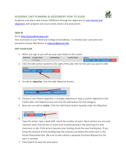
XVL Studio Basic/Standard/Pro Window at a Glance
(1) Menu bar
Main menus for operating the application.
(2) Toolbar
Frequently used functions such as view manipulations (1)
and controls are available here.
(2)
(3) Assembly Tree
The assembly structure of the 3D model is displayed
here.
(3)
(5)
(6)
(4) Control Panel
Material, Camera, Light, Layout controls are available.
(5) Manufacture Tree
Tree structure for manufacturing process.
(6) Structure Panel
Controls Layers, Snapshots, Process, and Disassembly.
(7) Edit Panel
Parts, Assembly, Annotation, Dimension, Process and
Interference Lists are available. Also Animation control
is shown in here.
(8) Graphic Window
Main place to operate on the 3D model as well as 2D
profile view.
(4)
(8)
(7)
(9)
(9) Status bar
Displays a command description.
January 2014
Lattice Technology, Inc.
4
Settings
January 2014
Lattice Technology, Inc.
5
License Setup
1.
2.
3.
4.
You can install license files by selecting Start > All
Programs > XVL Studio [Basic] > License Folder
and placing the license files in the folder.
Select Help > License to open the License dialog.
Specify the license source. When license server is
specified, XVL Studio will access the license server
for floating license.
You can specify the Studio grade in the License
dialog.
1
3
4
Select a grade and restart the
application.
To activate Basic, Standard or Pro,
the corresponding license must be
available.
January 2014
Lattice Technology, Inc.
6
Using Graphics Accelerator
You can use graphics accelerator to have the faster
graphic performance.
1.
2.
3.
Select Tools > Options to open the Options
dialog.
Select Graphics tab.
Select the Accelerator option.
–
–
–
Auto: Usage of graphics accelerator is automatically
determined by the application
Use: Force to use graphic accelerator.
Do not use: Do not use graphic accelerator.
* If graphics do not display correctly in the
window or if an operation takes too long, the
PC's graphics accelerator may not be set for
maximum compatibility with XVL Studio. In
such cases, do not use the graphic accelerator.
January 2014
Lattice Technology, Inc.
7
File Operations
January 2014
Lattice Technology, Inc.
8
Sample Models
You can find sample XVL models by selecting Start > All Programs > XVL Studio Pro > XVL Samples >
\Models
There are sample models for three file types, which includes P-XVL, V-XVL and U-XVL.
When XVL Studio is installed in the standard location, this maps to:
“C:\Program Files\Lattice\Studio2\Samples\Models\”.
* Unless you have specific reasons, use
U-XVL sample models for this is the
latest XVL format.
January 2014
Lattice Technology, Inc.
9
Sample Tool Models
You can find sample XVL tool models by selecting Start > All Programs > XVL Studio Pro > XVL
Samples > \Tools
There are sample models for three file types, which includes P-XVL, V-XVL and U-XVL.
When XVL Studio is installed in the standard location, this maps to:
“C:\Program Files\Lattice\Studio2\Samples\Tools\”.
* Unless you have specific reasons, use
U-XVL sample models for this is the
latest XVL format.
January 2014
Lattice Technology, Inc.
10
XVL File Type
There are two types of XVL file, P-XVL and V-XVL.
1.
You can change the default file type in the Options
dialog. (Menu: Tools > Options > Initialization tab)
•
•
•
•
•
2.
Select P-XVL if you need to save P-XVL files after
importing other file formats.
Select V-XVL if you need to save V-XVL files after
importing other file formats.
There are different versions of V-XVL. The latest version is
Ver.10 which is also called U-XVL.
When V-XVL is selected and a P-XVL file is imported, you
will save the model in selected version of V-XVL.
V-XVL files are not saved as P-XVL files.
When V-XVL Ver.10 (U-XVL) is selected, you can
specify the file format options.
•
•
1
2
Drawing speed: Faster loading speed, larger file size.
File size: Slower loading speed, smaller file size.
January 2014
Lattice Technology, Inc.
11
XVL File Format Comparison
P-XVL (*xv3)
V-XVL (*.xv2)
U-XVL (*.xv2)
V-XVL Ver. 9 or before
V-XVL Ver. 10 or later
Description
Allows for a high degree of
compression and has a
data structure with curves
and curved surfaces.
Almost equivalent to a
three-dimensional CAD.
Enables rapid reading and
reduced memory
consumption upon
completion of reading.
Combines the advantages
of P-XVL file format and VXVL file format.
Geometry
CAD surfaces and curves
Tessellated surfaces and
curves
CAD surfaces and curves
Accuracy
Up to 0.001 of original data
Up o 0.01 of original data
Up to 0.01 of original data
File size
Very small
Small
Very small
Graphic performance
Good
Excellent
Excellent
Loading speed
Slow
Fast
Fast
Memory usage
Moderate
Good
Excellent
Functional limitations
January 2014
•Activation/Deactivation is
not available.
•Interference check is not
available (simple check
only).
•“Check Difference”
command is not available.
•Cannot export IGES file.
•UV texture mapping is not
available.
Lattice Technology, Inc.
•UV texture mapping is not
available.
12
XVL Assembly File (*.xv0)
XVL Assembly File (*.xv0) is a structural XVL file.
It contains links to XVL part files and assembly
files. Reading the linked XVL files recursively
represents the entire assembly structure. When
this type of file is loaded, XVL Studio reads this
file and all the destination XVL files.
XVL Assembly File (XV0)
XV2 File
XV2 File
•XVL Assembly File is saved in either P-XVL or
V-XVL format.
•When XVL Assembly File is saved from XV2 or
XV3 file, assemblies will be saved as XV0 files,
and all parts will be saved as XV2 or XV3 files.
XV2 File
XV2 File
XVL Assembly File (XV0)
XV2 File
XV2 File
January 2014
Lattice Technology, Inc.
13
File Properties
File properties are checked from File > File Properties.
1.
2.
3.
4.
5.
6.
File Path: URL of the XVL file.
Total size: Display the file size.
Type: XVL File Type.
Calculation Error: Calculation error from original
data.
Copyright: Display copyright when available.
Copyright is added by XVL Signer.
Encryption Type: Display encryption type of the
XVL file. XVL file is encrypted by XVL Signer.
1
2
3
4
5
6
January 2014
Lattice Technology, Inc.
14
Opening XVL Files
1.
2.
3.
4.
1
Select File > Open to open the Open dialog.
Select an XVL file to open.
When you want to read the display settings
saved in the XVL file, switch on Import
display options.
Click Open.
* With Multi-CAD Direct Import option,
you can open CAD files directly.
4
2
3
January 2014
Lattice Technology, Inc.
15
Saving Files
1.
2.
Select File > Save as to open the Save as
dialog.
Select a format to save the file. You can
choose a type of output in the Save As dialog.
–
–
–
–
3.
V-XVL Geometry File (*.xv2): Generates a
single V-XVL file
P-XVL Geometry File (*.xv3): Generates a
single P-XVL file
V-XVL Assembly File (*.xv0): Generates
multiple XVL files composed of .xv0 and .xv2
files.
P-XVL Assembly File (*.xv0): Generates
multiple XVL files composed of .xv0 and .xv3
files.
Check on Export display options to include
display options such as color, font, tessellation,
and other options accessed through View >
Display Options.
January 2014
1
3
Lattice Technology, Inc.
2
16
Saving Files in Unicode
By saving XVL files with Unicode, multi-lingual characters
are displayed properly in Lattice Technology software.
1.
2.
Select Tools > Options to open the Options dialog.
In the General tab, select Unicode.
1
2
When XVL file is saved in Unicode,
multi-lingual characters are displayed
properly in XVL Studio.
January 2014
Lattice Technology, Inc.
17
Generating HTML files
In the Save As dialog, you can export XVL file embedded in HTML by switching on the Write HTML
file checkbox.
January 2014
Lattice Technology, Inc.
18
Importing Files
•
•
•
You can import other formats than XVL to XVL Studio.
By selecting File > Import, you can import the following
types of files:
– Geometry File: CAD file formats supported by the
Multi-CAD Direct Import option (displayed with “+”
mark) , IGES, Parasolid (*1), CATIA V4 (*2),
VRML2, OBJ, STL, DXF, DWG, PDF (3D PDF),
3DS (3D Geometry), U3D, STEP(*3) and XVL files.
– Geometry File from Folder: XVL files in the
specified folder.
– Geometry File at Position: Base location of
imported geometries are specified here.
– CSV File: parts, assembly, layer tables, process
and disassembly composition.
When 3D data is imported, XVL file type is determined
based on the options settings.
– See “XVL File Type” page for more detail.
*1) Require Parasolid import option
*2) Require CATIAV4 import option
*3) Require STEP import option
January 2014
Lattice Technology, Inc.
19
Exporting Files
•
•
You can convert XVL files to other 3D formats.
By selecting File > Export, you can generate the
following types of files out of XVL data:
– Geometry File: IGES(*1), VRML2, OBJ, STL, DXF,
3DS (3D Geometry), U3D
– CSV File: parts, assembly, layer tables, process
and disassembly composition.
– Image File: JPEG, PNG, BMP, TIFF
– Illustration File: CGM, SVG,EPS, DXF(*2)
– PDF File: 3D PDF
– HTML5 File: HTML5 Image based XVL(*3)
– 2D DXF File: DXF(*4)
*1) From P-XVL and V-XVL Ver.10 format only
*2) Require Illustration option
*3) Studio Standard/Pro only
*4) Studio Pro only
January 2014
Lattice Technology, Inc.
20
Viewing Operations
January 2014
Lattice Technology, Inc.
21
Viewing Operations 1/4
Pan 3D model
Set gazing point
Zoom in the specified area
3D rotation
Zoom in/out
January 2014
Lattice Technology, Inc.
22
Viewing Operations 2/4
Top
Bottom
Isometric
Left
Right
Back
Front
Rotate counterclockwise by 90
degrees
Rotate
clockwise by 90
degrees
Fit view
Undo view change
January 2014
Lattice Technology, Inc.
23
Viewing Operations 3/4
Keyboard short cuts:
–
–
–
–
–
Mouse + z: Pan 3D model
Mouse + x: 3D rotation
Mouse + Shift + x: 2D rotation
Mouse + c: Zoom in/out
Mouse + v: Zoom in the specified section
You can customize key assignment with the
customization file, Default.csv. The sample file can
be found at
C:\Program Files\Lattice\Studio2\Env
by default.
Pan 3D model
3D rotation
Zoom in/out
Zoom in the specified section
January 2014
Lattice Technology, Inc.
24
Viewing Operations 4/4
Viewing mode
Manipulation
Operation
Pan
Hold the middle mouse button/wheel #2 and drag your mouse.
Rotation (3D)
Hold the left mouse button #1 and drag your mouse.
Rotation (2D)
Operation of "Rotation (3D)" + SHIFT key.
Zoom
Roll the center mouse wheel #2.
Pan
Hold the middle mouse button/wheel #2 and drag your mouse.
Rotation (3D)
Hold the middle mouse button/wheel #2 and either left mouse button
#1 or right mouse button #3 and drag your mouse.
Rotation (2D)
Operation of "Rotation (3D)" + SHIFT key
Zoom
Hold the middle mouse button/wheel #2 and click on either left mouse
button #1 or right mouse button #3 and drag your mouse
Pan
After holding the SHIFT key and the middle mouse button/wheel #2,
drag your mouse.
Rotation (3D)
Hold the middle mouse button/wheel #2 and drag your mouse.
Rotation (2D)
Operation of "Rotation (3D)" + SHIFT key.
Zoom
After holding the CTRL key and the middle mouse button/wheel #2,
drag your mouse.
XVL classic
CATIA V5
Pro/ENGINEER
• You can use the CAD-emulating viewing modes by selecting Tools >
Options > Customize.
• In order to adjust the center of rotation, click the middle mouse
button/wheel #2. That will make the current location of cursor the center of
rotation.
January 2014
Lattice Technology, Inc.
25
Display Modes
You can change the display mode of the 3D graphic view by selecting the display mode icons from the
Display Toolbar.
Wireframe
Display Vertex
Shading
Hidden line
Wireframe+shading
January 2014
Lattice Technology, Inc.
26
Tessellation
•
You can adjust tessellation quality according to
your environment.
Rough
•
Normal
The Use LOD icon adjusts level of details
according to the view.
– By zooming in or out, you can see that Studio
re-tessellates the view.
Fine
January 2014
Lattice Technology, Inc.
Extra Fine
27
Display Options
Select Display Options icon from the Display Toolbar to
open the Display Options dialog box:
•
•
•
•
•
Setting colors
– Select the Display Color tab
– Specify color for each element
Changing projection
– Select the General tab and specify Projection
method.
Display/hide axis and grid
– Select the Axis/Grid tab
Changing display speed and quality
– Select the Display Speed / Quality tab
– Change parameters to optimize speed and quality
Hidden line display control
– Select the Hidden Line Display tab
– You can choose Hidden Line, Illustration, or All
Lines.
January 2014
Lattice Technology, Inc.
28
Element Display
You can display/hide selected elements from the 3D view without changing the display
status of each object.
1.
2.
3.
In the Display Toolbar, select the Display
Element icon.
Turn on/off elements to display/hide by
clicking them.
When the elements are turned off, they will not
be displayed in the 3D view window even
though they are still in the visible state.
1,2
3
January 2014
Lattice Technology, Inc.
29
Display Properties
You can display property value in tooltip when hovering the mouse cursor over a part.
1.
2.
3.
4.
Open the Options dialog and select the
Graphics tab.
Check on the Show information when the
cursor is over a part check box.
When Part Name is selected, part name will
be displayed in the tooltip.
When Property String is selected, specified
property value will be displayed in the tooltip.
1
2
3,4
January 2014
Lattice Technology, Inc.
30
Setting View Direction
1.
2.
3.
4.
5.
6.
Select View > View Direction > Specify to open the
Set View dialog.
Select Set Direction tab.
Select the coordinate axis that is to be the vertical
direction.
Select the Direction icon to change the view
direction.
Specify the Inclination angle to decide the
illustration view.
Click the Update button to apply change.
1
2
3
4
5
6
3
January 2014
4
Lattice Technology, Inc.
5
31
Full Scale View
1.
2.
3.
Projection method must be Parallel.
Select Tools > Options > Graphics to set the width of
screen.
Select View > Zoom > 1/1 to display the model with the
actual size to the scale defined in the CAD system.
1
3
2
January 2014
Lattice Technology, Inc.
32
Setting Clipping Position
You can set the position of clipping plane to reflect in the 3D view.
1.
2.
3.
Select View > Clipping Settings to
display the Clipping Setting dialog.
Change the clipping position of Near/Far
planes by using slider bars.
Click Set.
(Use F11 as shortcut key to reflect/release
clipping setting).
Clipped by near plane.
Clipped by far plane.
Slider bar
Clipping positions are adjusted to fit the model.
January 2014
Lattice Technology, Inc.
33
Swap Visibility
Select View > Swap Visibility to swap the visibility
of parts in the 3D view. The actual visibility
status remains.
(Use F10 as shortcut key to
reflect/release Swap Visibility).
Swap Visibility = OFF
Swap Visibility = ON
Hidden parts are displayed in
Swap Visibility mode.
January 2014
Lattice Technology, Inc.
34
Walk Through
By selecting Tools > View Operation Mode >
Walk, you can walk through in the view.
–
Toolbar icons changes into the Walk
Through mode.
Shift
Walk
–
Look Around
By selecting Tools > View Operation
Mode > Examine, you can go back to the
usual view mode.
January 2014
Lattice Technology, Inc.
35
Fly Through
By selecting Tools > View Operation Mode > Fly,
you can fly through in the view.
– Toolbar icons changes into the Fly
Through mode.
Translate
Fly
–
Look Around
By selecting Tools > View Operation
Mode > Examine, you can go back to the
usual view mode.
* While the Walk Through mode maintains the vertical height of motion, the
Fly Through mode can change the height of the view.
January 2014
Lattice Technology, Inc.
36
Selecting Objects
January 2014
Lattice Technology, Inc.
37
Selecting Elements
In the toolbar, specify the type of selection to pick the target to work on.
Body selection
-Select bodies
Shortcut key: D
Element selection
-Select surfaces,
vertices, edges
Annotation selection
- Select annotation
Dimension selection
- Select dimension
Part selection
-Select parts
Shortcut key: S
Assembly selection
-Select assembly
Shortcut key: A
Group selection
- Select grouped parts
Process selection
- Select process
Surface
Node selection
- Select disassembly part
Vertex
January 2014
Edge
Lattice Technology, Inc.
38
Selecting Hidden Parts
1.
2.
3.
4.
Select Edit > Select Inside to display the Object
Selection dialog.
Click on the surface to see parts hidden
underneath it.
All the parts underneath the clicked point will be
displayed in the dialog.
Select a part from the dialog.
1
2
3
Hidden part is
selected
4
January 2014
Lattice Technology, Inc.
39
Transparent and Fit Selection
Fit selection
Opaque selection
•
•
•
Transparent selection
By clicking on the Opaque Selection icon, you can select a part to be highlighted and rest of the
others to be transparent.
By clicking on the Transparent Selection icon, you can select a part to be transparent.
By clicking on the Fit Selection icon, you can fit the selected part to the entire Graphic window.
Opaque Selection
January 2014
Transparent Selection
Lattice Technology, Inc.
Opaque Selection + Fit Selection
40
Authoring
January 2014
Lattice Technology, Inc.
41
Part Display Controls
1.
2.
3.
4.
5.
Clicking each node of the Assembly Tree
highlights the corresponding element(s).
Use + and – to control display of the tree
structure.
You can select multiple nodes by holding
Ctrl or Shift key.
Switch on and off the check boxes to
display or hide each part (Shortcut key:
F9).
Right click menu on the Assembly Tree:
a)
Shows the selected element when it
is hidden. Nothing happens when it
is already displayed.
b)
Hides the selected element
c)
Displays the selected element only
d)
Displays all elements.
1
2
4
5
a
b
c
d
January 2014
Lattice Technology, Inc.
42
Assembly Tree Editing 1/2
Before editing the Assembly Tree, expand the assembly structure
of the 3D model so that part positions will be maintained.
1.
2.
3.
4.
Load the 3D model into XVL Studio.
Click on Tools > Modify Shape and Assembly > Expand
menu to bring up Expand Assembly Structure dialog box.
Select Relative for How to Expand Instances and Up to
parts for the Target Elements.
Click OK to expand the tree structure.
January 2014
Lattice Technology, Inc.
43
Assembly Tree Editing 2/2
Adding a new group:
1.
Select a target group that is to be the parent of
the newly created group.
2.
From Right Click Menu, select Add
Part/Assembly.
3.
Double-click the newly created group to open
the Properties dialog.
4.
Edit the Name field to give an appropriate name.
6
1
Moving a part:
5.
Drag a target part, hold the mouse button, and
drop it onto a destination group.
6.
Alternatively, you can use Cut/Copy/Paste of
the right click menu.
Deleting a group:
7.
Click on the target group, right click on it, and
select Delete.
8.
Alternatively, you can click on the target group
and push the Delete key on your keyboard.
January 2014
7
2
5
4
Lattice Technology, Inc.
44
Creating Multiple Copies of Parts
1.
2.
3.
4.
5.
6.
Select Tools > Copy Part Array to open the Copy Part Array dialog.
Select parts to copy.
Specify the Base location and offset values.
Specify the number of copy.
Select other copy options.
Click the Execute button.
1
2
Original part
3
4
5
Multiple copies of the part are
created in a single command.
6
January 2014
Lattice Technology, Inc.
45
Viewing Part Properties
1.
2.
3.
4.
5.
Select a part on the Assembly Tree.
To show the Properties dialog, select Properties from
the right click menu.
Select tab that has the property section name to view the
properties.
–
Some properties defined in the CAD system are
inherited to converted XVL.
You can add/change properties and their values. Click the
Add/Modify button to reflect the change.
Click the Set button and fix the change.
3
4
1
2
January 2014
Lattice Technology, Inc.
5
46
Creating User Coordinate System
1.
2.
3.
4.
5.
Select Tools > User Coordinate System to
open the User Coordinate System dialog.
Select New for the Target Object.
Use the Set Location option to specify the
position of the user coordinate system.
Click the Execute button to create the user
coordinate system.
You can select the user coordinate system from
the 3D view or the Assembly Tree.
1
2
3
4
3
January 2014
Select position
5
Lattice Technology, Inc.
User coordinate
system
47
Using Grid Plane
Grid Plane can be used when you evaluate/author the 3D
models.
To display the Grid Plane:
1.
Select View > Display Element and select the Grid
type.
To change the interval of grid:
2.
Open the Display Options dialog and select the
Axis/Grid tab.
3.
Set the Grid Interval and Count, and then click OK.
1
2
3
January 2014
Lattice Technology, Inc.
48
Moving Parts (Normal mode)
1.
2.
3.
4.
5.
6.
From the Operation Toolbar, click on the Move
Part icon to open the Move Part dialog.
Select part(s) in the Graphics Window.
–
You can make multiple selection by holding
the Ctrl or Shift key.
After selecting part(s), click on the Selecting
button in the Move Part dialog. The button
display is changed to Selected.
Using the Manipulator or the Translation dialog,
move the selected part(s).
–
To change the view angle, use view hotkeys
such as z, x, c, and v.
–
You can also select the Translate
Manipulator from Right Click Menu.
To create trace lines, switch on Create trace line.
Click the Execute button of the Translation
dialog to settle the part(s).
1
2
3
4
5
6
January 2014
Lattice Technology, Inc.
49
Moving Parts (Simple mode)
1.
From the Operation Toolbar, click on the Move
Part icon to open the Move Part dialog.
Select ‘Simple’ for the Operation mode.
Click on the Start selection button.
Select part(s) in the Graphics Window.
Using the Manipulator or the Translation dialog,
move the selected part(s).
–
To change the view angle, use the keyboard
short cuts such as z, x, c, and v.
–
You can also display the Parallel Manipulator
by right-click and selecting menu >
Manipulator > Translate Manipulator.
Select next part then repeat moving.
2.
3.
4.
5.
6.
4
January 2014
2
3
6
5
Lattice Technology, Inc.
50
Adding Notes
1.
2.
3.
4.
–
–
–
–
–
–
–
–
–
–
–
5.
1
Click on the Edit Note icon in the Operation Toolbar.
In the Edit Note dialog, make sure the Edit Mode is
“New”.
In the Graphics Window, click on a target element to
add a note. Then, drag your mouse cursor and
release at a point where you would like to place the
Note.
Type in the text and set the properties for the text.
Note Type: You can create note in 2D and 3D shape.
Direction: You can change the orientation of note.
Link: You can define a hyper link to another resource.
Image: Alternatively, you can specify an image.
Note Direction: Useful to align the direction.
Leader Line: Use these buttons to generate multiple
leader lines.
Note/Line Color: Specify the color of notes/leader lines.
Background: Specify background color of notes.
Show frame: Note text is framed.
Font: You can set your own favorite font.
Tip Form: Select the tip form of the leader line.
3
4
After setting the parameters, click the Execute button
to add the annotation.
January 2014
2
Lattice Technology, Inc.
5
51
Editing Notes
1.
2.
3.
4.
Double-click a note to edit.
The Edit Note dialog is displayed, and you
can edit the note parameters.
You can also select multiple notes and align
their directions.
–
You can see a preview with blue color.
To add multiple leader lines to one note, click
the Leader Line toggle button then click on
the target part. Click the Execute button to
add another leader line.
2
3
4
1
January 2014
Lattice Technology, Inc.
52
Initial Setup for Notes
You can setup the default parameters in the Initial
Setup dialog.
1.
2.
3.
On the Edit Note dialog, click the Initial Setup
button to open the Initial Setup dialog box.
Set parameters for notes.
–
Note: You can choose either 2D or 3D.
–
Make property comment character line:
Displays the property values for each
group. The format is:
${property_name}
–
Parts Name as comment character
line: Displays the part names of the
groups
–
Enter desired comment character line:
Allows input of arbitrary comments.
–
Styles: You can define styles of notes.
–
Tip Form: You can define the type of
arrow head.
After setting parameters, click OK.
January 2014
Lattice Technology, Inc.
2
1
3
53
Simple Measurement
1
Easy measurement:
1.
2.
3.
4.
5.
From the Measurement Toolbar, select the type
of measurement.
Select target(s).
–
As you move your mouse cursor, the
corresponding points, edges, or faces are
highlighted.
Choose the measurement method.
Adjust the position of the dimension.
To finish the measurement mode, right-click in the
Graphic window and select Cancel.
2
2
3
4
January 2014
Lattice Technology, Inc.
54
Initial Setup for Measurements
a
Initial Setup
By selecting Initial Setup icon from the Measurement
Toolbar, you can specify the initial settings of
dimension displays.
b
c
a)
b)
c)
d)
Select 2D or 3D dimensions.
Specify the number of decimals.
Turn the check on if you display unit in dimension
(for mm / inch).
Set dimension styles.
January 2014
Lattice Technology, Inc.
d
55
Parallel/Serial Dimension
1
Parallel/Serial dimension:
1.
2.
3.
4.
5.
Check on the Parallel (Serial) Dimension.
Select the type of measurement.
Select target and create measurement.
Select next target to create another dimension.
Continue to select more target to create more
dimensions.
2
3
4
5
Serial Dimension
January 2014
Lattice Technology, Inc.
56
Advanced Measurement
For other measurements that are not available from icons,
you can display the Measurement/Dimension dialog
to select from more methods.
1.
2.
3.
4.
5.
6.
Select Evaluation > Measure Dimension to display
the Measurement/Dimension dialog.
Select the type of measurement from the tab menu.
Select “Arbitrary element” for the type of the element
to pick up. Make sure the “Selecting” button is
enabled.
Pick the measuring elements from the 3D view.
After picking up sufficient number of elements, the
corresponding dimension is displayed. Drag the
dimension and fix the dimension position.
You can edit the dimension by clicking the Edit
Dimension icon.
6
January 2014
4
1
2
3
5
Lattice Technology, Inc.
57
Changing Measurement Unit
Change measurement unit:
1. Select Tools > Options > General, to use the
inch in measurement.
Convert existing measurement unit:
2. Select Evaluation > Convert All dimensions to
switch measurement values between “mm” and
“inch”.
2
January 2014
1
Lattice Technology, Inc.
58
Basic Cross Sectioning 1/3
Creating a Cross-section:
1.
Select the Create/Edit Cross-section icon from
the Cross-Section Toolbar.
2.
Specify the location of cutting plane from the Set
Location list or by using manipulator.
3.
To specify the location of cutting plane by
coordinate values, select Specify Number from
the Edit Cross-section menu and enter the
value.
4.
Select Create and Display Cross-section from
the Edit Profile menu and create a crosssection.
Cross-section Toolbar
1
2
3
4
January 2014
Lattice Technology, Inc.
59
Basic Cross Sectioning 2/3
Displaying a cross-section:
1.
Select a profile from the Cross-section List.
2.
To display cross sectional view of parts,
select Display Cross-section.
3.
To go back to normal view, select Hide
Cross-section.
4.
To display profile line only select Display
Profile Line Only.
1
2
3
4
January 2014
Lattice Technology, Inc.
60
Basic Cross Sectioning 3/3
Editing a cross-section:
1. Select a profile from the Cross-section List.
2. Select the Create/Edit Cross-section icon from
the toolbar to start edit.
3. Change the location of cutting plane then select
Create and Display Cross-section.
1
2
3
January 2014
Lattice Technology, Inc.
61
Advanced Cross Sectioning 1/4
Creating a Profile:
1. Select Evaluation > Cross-section to open
the Cross-section List dialog.
2. Click the New Cross-section button to start
cross-sectioning. The Edit Cross-section
dialog and the profile view will be displayed.
1
2
Edit Cross-section dialog
January 2014
Lattice Technology, Inc.
62
Advanced Cross Sectioning 2/4
3.
In the Edit Cross-section dialog, specify the
cross-section using the following tools.
a)
b)
c)
d)
4.
Set the location of cross-section plane. You can
use icons to change the location or direction of
the cutting plane.
You can also change the position or direction of
the cutting plane by using the manipulator or
Translation/Rotation tools.
Use Display Options to show/hide elements in
the view windows.
Check on Create profile lines upon execution to
generate profile lines.
3
b
a
Click the Add button to create cross-section.
b
c
d
January 2014
Lattice Technology, Inc.
4
63
Advanced Cross Sectioning 3/4
Viewing cross sections:
1.
Select Evaluation > Cross-section to open the
Cross-section List dialog.
2.
Choose a Profile.
3.
Click on the Display cross-section button.
2
3
January 2014
Lattice Technology, Inc.
64
Advanced Cross Sectioning 4/4
More Controls:
1.
You can specify the part to cut.
2.
You can define multiple Profiles.
–
By specifying the intervals and range, you
can create multiple profiles at once.
3.
While you are defining the cross section for a
selected part, you can change the visualization
style of other parts.
a)
Select “Selected Parts” in Section.
b)
Select the method to display other parts.
c)
Select the target parts.
1
2
3
January 2014
a
Lattice Technology, Inc.
b
c
65
Editing Materials
6
By editing Material, you can change colors, transparency, and
other parameters.
1.
2.
3.
4.
5.
6.
Select the Material tab in the Control Panel to
open the Material Panel.
Click on the Add icon. A new material
“Material-1” is created.
Double-click on the target material object to
open the Material Properties dialog.
Edit material parameters and click Set to apply
the change.
Select the target group or surface.
Click on the Assign Material icon to apply the
material.
2
6
3
4
1
5
Select
January 2014
Lattice Technology, Inc.
66
Editing Cameras
Editing cameras allows you to save the viewpoint and
show/hide status.
3
Creating a new camera:
1.
2.
3.
Click on the Camera tab of Control Panel to open the
Camera Panel.
Change the viewpoint of the 3D model to which you
want to save in the camera.
Click on the Add icon. A new camera “Camera-1” is
created.
Editing a Camera:
4.
5.
6.
Select the “Camera-1” and open the Properties dialog
from the right-click menu.
Edit the Camera Properties dialog.
•
Change the camera name.
•
Check the Save view status to include the display
status of parts in the camera.
•
Click the Select View button to apply the current
view to the camera.
Click Apply and close the dialog.
2
8
4,7
1
5
6
Apply the Camera:
7.
8.
9.
Select the target Camera
Click on the Apply Camera icon.
Or double-click the camera to apply it.
January 2014
Lattice Technology, Inc.
67
Editing Lights
Creating a new light object:
1. Click on the Light tab of Control Panel to
open the Light Panel.
2. Click on the Add icon. A new light “Light-1” is
created.
3. Double click “Light-1” to open the Light
Properties dialog.
4. Edit the Light Properties.
•
•
•
5.
2
3,6
4
1
Parallel light: Check this to turn on light parallel.
Point light: The light radiates out from the
specified position.
Spot light: The light illuminates a certain
conical range from the specified position.
5
Click Apply and close the dialog.
Enabling and disabling light:
6. You can enable or disable the light objects
by switching on or off the check boxes inside
the Control Panel.
Parallel Light
January 2014
Lattice Technology, Inc.
Point Light
Spot Light
68
Editing Layouts
When you change the positions of parts, you can save the
parts layout.
2
Creating a new Layout:
1.
2.
3.
Click on the Layout tab of Control Panel to open the
Layout Panel.
Click on the Add icon. A new layout “Position-1” is
created.
Double click “Position-1” to open the Properties dialog
and change the name.
3
4
1
Applying the Layout:
4.
5.
6.
56
Select the target layout
Click on the Apply Layout icon.
By clicking on the Apply Layout to Targets icon, you
can apply the layout only to the selected parts.
January 2014
Lattice Technology, Inc.
69
Editing Textures
1.
2.
3.
4.
5.
6.
Click on the Texture tab of Control Panel to open the
Texture Panel.
Click on the Add icon to open the Texture Properties
dialog.
Specify the texture image file. Sample texture file is
available in the following folder.
“C:\Program
Files\Lattice\Studio2\Samples\texture”.
To embed texture to XVL file, check on Embed.
Select the texture mapping type.
Click Set and close the window.
9.
2
3
1
3
Mapping texture:
7.
8.
10
8
Adding a new texture:
Select the target from the 3D view window.
Select the texture and click the Apply Projection
Mapping button.
When mapping Normal texture, set the parameters in
the Apply Projection Mapping dialog and click
Execute to apply.
4
9
5
7
6
Deleting texture:
10. Select the target from the 3D view window and click the
Remove Textures icon.
January 2014
Lattice Technology, Inc.
70
Editing Snapshots
3 a b 4
A snapshot is a capture of the state of 3D model including
camera view and layout.
2
Adding a new snapshot:
1.
In the Structure Panel, select the Snapshot tab to open
the Snapshot panel.
2.
Click the Add Snapshot icon to add the snapshot.
Current 3D view state is saved in the snapshot.
1
Applying a snapshot:
3.
Select a snapshot and click on the Apply Snapshot
icon.
a)
b)
The Apply Specified Elements icon allows you to
selectively apply the element of the snapshot.
The Apply Layout to Parts icon allows you to selectively
apply the parts layout of the selected parts.
Updating a snapshot:
4.
Select a snapshot and click on the Update Snapshot
icon. Snapshot will be replaced by the current view
state.
Default
Illustration
January 2014
Lattice Technology, Inc.
71
Using the Base Layout 1/4
You can set a base layout in the 3D model.
Using the base layout, snapshots can be applied relative to the base layout.
Base layout is updated
after changing the axle
position.
Original part
layout.
(Axle position changes)
Base layout
Snapshot
Snapshot is created
after changing the
tire position.
January 2014
Snapshot
Snapshot is applied
relative to the base
layout.
Lattice Technology, Inc.
72
Using the Base Layout 2/4
Setting the base layout:
1. In the Options dialog (Initialize tab), turn on
Register base layout.
2. Click Apply and close the dialog.
3. When a 3D model is opened, the base layout is
automatically set to the initial part positions.
Updating the base layout:
4. Change the part positions.
5. Select Edit > Base Layout > Update Base
Layout. The base layout is updated to the
current part positions.
Applying the base layout:
6. Change the part positions.
7. Select Edit > Base Layout > Apply Base
Layout. The base layout is applied to the 3D
model.
January 2014
1
2
3
4, 7
Lattice Technology, Inc.
5
Base layout
6
73
Using the Base Layout 3/4
Creating snapshot using the base layout:
1. Open Options dialog in the Snapshot toolbar.
2. Check on Relative distance from base layout.
3. Click OK and close the dialog.
4. Create snapshots. Snapshots will include the
relative distance from the base layout.
1
3
Snapshot-1
3
Snapshot-2
2
January 2014
Lattice Technology, Inc.
74
Using the Base Layout 4/4
Applying snapshots relative to the base layout:
5. Apply Snapshot-1 and change the part positions.
6. Update the base layout.
7. Apply Snapshot-2. Snapshot will be applied relative to
base layout.
8. To apply a snapshot to absolute positions, in the
Options dialog specify How to Apply Layout to be
Absolute location.
6
Snapshot-1
Base layout
8
5
8
7
Snapshot-2
January 2014
Lattice Technology, Inc.
75
Engineering Functions
January 2014
Lattice Technology, Inc.
76
Dynamic Collision Detection
1.
2.
3.
4.
5.
6.
Select Evaluation > Dynamic Collision Detection to open the
Dynamic Collision Detection dialog.
Select the parameter from the dialog.
Click Start to start dynamic collision detection.
Dynamic collision detection mode is now activated.
Select Tools > Move Part to open the Move Part dialog.
As you move parts, collision is detected by highlighting the
related parts.
1
3
2
6
4
* With XVL Studio Pro grade, Dynamic
Collision Detection is available with process
animation.
January 2014
Lattice Technology, Inc.
77
Checking Structure Differences 1/2
You can check structure differences between two input XVL
files.
4
1st Version
1.
2.
3.
4.
5.
6.
2nd Version
Open the 1st version (original version) of the model.
Import the 2nd version (new version) of the model.
In Assembly Tree, select two top assemblies.
On the selection of the Assembly Tree, right click and
select Detect Differences > Structure Comparison
down to Parts.
In the confirmation dialog, click OK.
Six layers are created in the Layer tab of the
Structure Panel.
January 2014
4
Lattice Technology, Inc.
5
6
78
Checking Structure Differences 2/2
•
By changing the display status of each layer, you can selectively
display different parts or uniquely existing parts.
– Common_Group-0
•
–
Different_Group-0
•
–
•
Common parts to original and new versions.
Parts belonging to new version that have underwent changes
between original and new versions.
Original_Group-1
•
•
Parts unique to original version.
Different_Group-1
•
–
Different_Group-0
Common_Group-1
•
–
Parts belonging to original version that have underwent changes
between original and new versions.
Original_Group-0
•
–
Common parts to original and new versions.
Different_Group-1
Parts unique to new version.
The original version is composed of Common_Group-0,
Different_Group-0, and Original_Group-0.
The new version is composed of Common_Group-1,
Different_Group-1, and Original_Group-1
Common_Group-1
January 2014
Lattice Technology, Inc.
79
Simple Geometry Difference Check 1/2
You can check the geometry difference of two parts in face
level.
1
Compare
1.
2.
In the Assembly Tree, select two target parts.
On the selection of the Assembly Tree, right click and
select Detect Differences > Shape Comparison
Between Parts.
2
January 2014
Lattice Technology, Inc.
80
Simple Geometry Difference Check 2/2
3.
4.
4
In the Assembly Tree, Compare_Group is created.
Display only each group under Compare-1 to check the
geometry difference between parts.
Common shape
3
Shape in part A only
Shape in part B only
January 2014
Lattice Technology, Inc.
81
Questions?
E.
T.
F.
W.
January 2014
[email protected]
+1.415.274.1670
+1.415.274.1671
www.lattice3d.com
Lattice Technology, Inc.
82
© Copyright 2026 ExpyDoc