PHYSICAL REVIEW E 90, 062505 (2014)
Multiscale models of colloidal dispersion of particles in nematic liquid crystals
T. P. Bennett,1 G. D’Alessandro,1 and K. R. Daly2
1
Mathematical Sciences, University of Southampton, Southampton, England, United Kingdom
2
Engineering Sciences, University of Southampton, Southampton, England, United Kingdom
(Received 13 June 2014; revised manuscript received 16 September 2014; published 15 December 2014)
We use homogenization theory to develop a multiscale model of colloidal dispersion of particles in nematic
liquid crystals under weak-anchoring conditions. We validate the model by comparing it with simulations by
using the Landau–de Gennes free energy and show that the agreement is excellent. We then use the multiscale
model to study the effect that particle anisotropy has on the liquid crystal: spherically symmetric particles always
reduce the effective elastic constant. Asymmetric particles introduce an effective alignment field that can increase
the Fredericks threshold and decrease the switch-off time.
DOI: 10.1103/PhysRevE.90.062505
PACS number(s): 61.30.Dk, 61.30.Gd, 61.30.Hn
I. INTRODUCTION
There is considerable research interest in colloidal, or
doped, nematic liquid crystals. These consist of micronto nanometer-sized particles suspended in a nematic host.
Dopants may posses permanent electric or magnetic dipoles
leading to ferronematic systems, or their influence may be
due to mechanical anchoring on the dopant surface. Doped
nematics can be loosely categorized as being in the strongor weak-anchoring limit by the size of the dopants and the
anchoring strength.
Systems dominated by the anchoring at the surface of
dopants have been investigated experimentally [1,2], geometrically [3], and numerically [4]. In these systems complex defect
structures encircling dopant particles can form. In the stronganchoring limit point and line defects and their accompanying
elastic distortions introduce long-range correlations between
the dopant particles [4]. Numerical studies have shown that
spherical colloids can aggregate into two-dimensional crystals
bound together by topological defects [5]. The stability of
a particular defect configuration depends not only on the
particle size but on the anchoring strength and applied field [6].
Conversely, in the weak-anchoring limit, defects are not
induced and elastic deformations are small, even though
aggregation still occurs on a long enough timescale [7]. In
general, stiffening the liquid crystals, weakening the anchoring, and reducing particle size all move a system towards the
weak-anchoring limit [7].
In this paper we focus on the weak-anchoring case, i.e.,
the liquid crystal alignment is dominated by elastic and
electrostatic forces with the dopants acting to alter rather
than dominate the properties of the liquid crystal. Their
effect, however, may still be significant. For example, gold
nanoparticle inclusions [8] have a considerable effect on
the liquid crystal hosts: they lower the nematic-isotropic
transition temperature [9], increase the switching speed [10],
and introduce tunability of the dielectric anisotropy [11]. More
recently, gold particles [12,13] and layered structures [14] have
been studied for their applications to the creation of tunable
metamaterials.
Ferromagnetic and ferroelectric particles are other classes
of dopants that have attracted significant interest because of
their potential to improve the properties of liquid crystals.
Interest in ferronematic systems was initially raised by
1539-3755/2014/90(6)/062505(14)
de Gennes [15]: the addition of dopants alters the response of
the nematic host to external fields due to the coupling between
the dopants dipole and applied field. Because the orientation
of the dopants is correlated with the director, the orienting
effect of the applied field on the dopants is felt by the nematic.
Current theories on liquid crystals doped with ferromagnetic
[16–20] or ferroelectric [21,22] particles assume a mean field
interaction between the particles and the director field.
Effective medium theories for doped liquid crystals are
based on additional terms added to the free energy of the
liquid crystal. These terms characterize the reorientation of the
dopant particles in addition to their interaction with the liquid
crystal and external fields. While the dielectric response of the
liquid crystal is altered by these terms, in general these theories
neglect the influence of the dopant on the elastic properties of
the nematic: the anchoring is assumed to align the dopant with
the nematic without causing additional stiffness or memory
effects in the nematic. More importantly, phenomenological
parameters are required to describe the coupling between
dopants dipole and external fields. These parameters have been
fitted with some success using experimental data [23], but there
is clearly a need for a macroscopic model whose parameters
are derived self-consistently from the microscopic equations.
This paper outlines the first steps in developing such a
theory. This theory aims to produce a macroscopic model
for colloidal nematics that explicitly treats the microscopic
physics and geometry of the colloidal particles. We consider a
liquid crystal confined by a set of evenly distributed inclusions
of fixed orientation and position. The inclusions we consider
may be identified with a periodic microstructure or with fixed
dopant particles. We discuss in Sec. IV the consequences of
this approximation and how it may be relaxed in future work.
The size and volume fraction of the particles are assumed
small with respect to the macroscopic size of the device.
Hence, the spacing between these inclusions is small with
respect to the length scale of interest, but not so small that
a Q-tensor macroscopic theory is no longer valid (e.g., 30
to 50 nm with respect to micron-sized macroscopic lengths).
This length scale ratio forms the basis of the homogenization
technique and allows us to derive averaged or “homogenized”
equations which capture the underlying geometrical effects of
the inclusions through a representative cell problem [24]. The
cell problem allows us to relate the macroscopic parameters
to the microstructure of the particle–liquid-crystal interaction.
062505-1
©2014 American Physical Society
T. P. BENNETT, G. D’ALESSANDRO, AND K. R. DALY
PHYSICAL REVIEW E 90, 062505 (2014)
This approach enables us to form a direct link between the
geometry of the microstructure or dopant distribution and the
effective material parameters used to describe the macroscopic
system.
Existing literature relating to homogenization and liquid
crystals [25–27] prove under general conditions the convergence of the homogenization scheme based on the director
representation of the nematic liquid crystal. In particular, they
assume that the anchoring is characterized by a preferred
direction on the dopant surface and a single anchoring energy.
Here we consider a similar system, but derive the multiscale
equations using the Q-tensor formalism. Our aim is to verify
them against numerical simulations and to use them to study
the effect of particle anisotropy on the liquid crystal.
The multiscale approach offered by homogenization theory has many advantages with respect to a full Q-tensor
simulation. First, it clearly identifies the physical effects of
the inclusion of particles on the liquid crystal, in terms of
modification of the macroscopic parameters of a pure liquid
crystal, or the creation of new terms and effective fields.
Second, it allows these corrections and the resulting effective
fields to be computed directly from a microscopic theory.
While these computations may be complex and costly, they are
required only once for identical inclusions. Finally, the complex geometry resulting from the inclusion of particles severely
increases the computation time of a Q-tensor simulation. The
homogenized equations do not suffer from this effect, because
their geometry is the same as that of an undoped system.
This paper is organized as follows: in Sec. II we develop
the multiscale model, present the main results of this paper,
and outline the assumptions we made in modeling our system.
In Sec. III we validate the model by comparing numerical
simulations of the full system with the predictions of the
homogenized equations. We then use the homogenized model
to study the effect of the particle inclusion on the Fredericks
transition and on the switch-on and -off time of a planar cell.
In particular, we show that by using ellipsoidal inclusions the
switch-on or switch-off time can be reduced. Finally, in Sec. IV
we discuss the approximations at the base of the homogenized
model and how they may be relaxed.
II. THEORY
A. Governing equations
We describe the alignment of the nematic by the Q
tensor [28] which, for a general biaxial nematic liquid crystal,
is given by
I
I
3
3˜
ˆ ⊗m
ˆ −
S˜ dˆ ⊗ dˆ −
Q˜ =
+
β m
. (1)
2
3
2
3
Here S˜ is the scalar order parameter and β˜ is the biaxiality
parameter, I is the identity matrix, dˆ is the liquid crystal
ˆ is a unit vector defining the second
director field, and m
˜ which is orthogonal to the director. We
principal axis of Q,
describe the liquid crystal orientation through a free energy
minimization.
In constructing our model we make several assumptions
about our system. In order to apply homogenization we assume
periodicity, i.e., the inclusions form a periodic array of unit
Ly
B
Γi
Ω np
Ω
D
Lx
FIG. 1. (Color online) Domains used in defining scale separation.
The macroscopic domain consists of an open region D, with external
boundary ∂D, constructed from unit cells with outer boundaries B
and metallic inclusions of volume np and boundary i .
cells as shown in Fig. 1 with period Ly . Each cell consists
of a volume , the hashed region shown in Fig. 1 containing
liquid crystal and a metallic inclusion of volume np with
boundary i , where the subscript i labels the inclusions. We
label the external boundary of a cell B. The macroscopic
domain D consists of an array of unit cells, with macroscopic
boundary ∂D. The system has a separation of scales which we
L
quantify by the smallness parameter η = Lyx , where Lx is the
size of the macroscopic system. The homogenization process
involves studying the limiting behavior of a system as η tends
to zero while the total size of the system remains constant.
We consider a system of constant size Lx as the size of the
periodic microstructure Ly tends to zero and the number of
inclusions diverges. The inclusions are assumed to remain in
fixed positions and orientations, but we pose no restrictions on
their geometry. The total free energy of the nematic is
F˜ =
(2)
F˜ B + F˜ t + F˜ e dV +
F˜ s dS.
D
∪i i
The bulk elastic F˜ B , thermotropic F˜ t , electrostatic F˜ e , and
surface F˜ s free energy density of the nematic are given by
LB
˜ 2,
|∇ Q|
(3a)
F˜ B =
2
√
1
F˜ t = A(T − T ∗ )Tr(Q˜ 2 ) − 6BTr(Q˜ 3 )
2
1
+ C[Tr(Q˜ 2 )]2 ,
(3b)
2
1
˜
(3c)
F˜ e = − 0 Tr(Q˜ E),
3
μ˜
F˜ s = (Q˜ − Q˜ S )2 .
(3d)
2
Here A, B, and C are the Landau coefficients which are assumed to be temperature independent. All temperature effects
are confined to the T − T ∗ term, where T is the temperature
and T ∗ is the pseudocritical temperature at which the isotropic
phase becomes unstable. LB = 3KS˜ 2 where K is the elastic
constant of the liquid crystal, is the dielectric anisotropy,
and 0 is the vacuum permittivity. μ˜ is the surface-anchoring
062505-2
MULTISCALE MODELS OF COLLOIDAL DISPERSION OF . . .
PHYSICAL REVIEW E 90, 062505 (2014)
energy density and Q˜ S is the preferred alignment tensor which
parametrizes the surface free energy. The electrostatic tensor
E˜ is related to the electric potential by
I
3
˜
˜
˜
∇φ ⊗ ∇φ −
,
(4)
E=
2
3
Details of the nondimensionalization used are given in the
Appendix. The governing equations can be derived from a
dissipation principle [31]. When fluid flow is neglected the
dissipation principle takes the form
where φ˜ is the electric potential. We follow the approach
outlined in Ref. [29] and express the scaled Q tensor, preferred
alignment tensor, and electrostatic tensor on the basis of
traceless symmetric tensors. The components on this basis
are
˜
a˜ m = Tr[T (m) Q],
˜
e˜m = Tr[T (m) E],
a˜ Sm = Tr[T
(m)
Q˜ S ],
(5a)
(5b)
(5c)
which form the mth components of the vectors a˜ , e˜ and a˜ S ,
where T (m) , m = 1, . . . ,5 are a basis of traceless symmetric
tensors defined by Eqs. (A1) in the Appendix.
We are interested in the case where neither the surface
energy nor the bulk energy dominates the behavior of the
system. We expect that in this regime there will be a richer
interplay between the two constituents, particles and liquid
crystal, that will show the potential of homogenization theory
to obtain realistic macroscopic equations. To this end we
require that the ratio of bulk to surface energy remains constant
as η tends to zero. This imposes constraints on the strength of
the surface anchoring in the system because the total surface
area of the inclusions tends to infinity as η tends to zero. To
determine the scaling of the anchoring energy we estimate the
total bulk elastic and surface energy in the system. For the
system pictured in Fig. 1 the dimensional bulk elastic energy
F˜B and surface energy F˜S are given by
LB
˜ 2 dV ∼ Vlc LB ,
F˜B =
|∇ Q|
(6a)
2
2
D
μ˜
μ˜
(Q˜ − Q˜ S )2 dS ∼ A ,
(6b)
F˜S =
2
2
i
i
with Vlc being the total volume of liquid crystal and A
being the total contact area with the inclusions. For spherical
inclusions of radius r = ηr0 , the total surface area of the
inclusions is A = 4π r02 η2 N where N is the total number
of inclusions. The total number of inclusions in the system
˜ −1 . The
is N = η13 , hence the surface energy F˜S scales as μη
total bulk elastic energy is independent of η, hence, for a
system with a constant ratio of surface to bulk free energy, the
anchoring energy density μ˜ must scale as η. This constraint
is compatible with the requirement that the anchoring is weak
enough not to induce defects in the particle neighborhood. As
shown by Ref. [30] no defects form if μr/L
˜
B 4. As both
μ˜ and r scale with η this relation is always satisfied in the
homogenization limit, η → 0.
Finally, we assume that the inclusions can be treated as
ideal conductors and solve Maxwell’s equations subject to a
constant floating potential across each individual inclusion.
This approximation is justified for dopant particles considered
here under ac conditions, because the penetration depth of the
electric field is far smaller than the particles.
∂ F˜V
∂ F˜V
∂R
=
−
,
∂ai,t˜
∂ x˜j ∂ai,j
∂ai
(7)
with the dissipation function given by
2
1
∂a
R= ζ
.
2
∂ t˜
(8)
Here ζ is related to the Leslie rotational viscosity γ1 by ζ =
γ1
, t˜ is time, and F˜V is the total volume free energy
3S˜ 2
F˜V = (F˜ e + F˜ t + F˜ B )dV .
(9)
D
In the limit of static configurations the dissipative principle
produces the Euler–Lagrange equations minimizing the free
energy of the nematic. The governing equations are obtained
from Eq. (7), and the boundary conditions on the inclusions
are time independent and are found from minimizing the free
energy over ∪i i . In nondimensional form these are
∂a
, x ∈ D,
(10a)
ξ˜02 ∇ 2 a + χ˜ a e + M (a) a =
∂t
nˆ · ∇a = W (aS − a), x ∈ , (10b)
a = b(x),
x ∈ ∂D,
(10c)
where b(x) is the prescribed value of a(x) on the macroscopic
boundary ∂D, and nˆ is the unit normal on i . The nondimenC 2 0
9CLB
˜ a = 902L
sional elastic constant is given by ξ˜02 = 2B
2 L2 , χ
2 B3
x
x
˜ x
is the dimensionless dielectric anisotropy, W = μL
is the
2LB
dimensionless anchoring strength, and 0 is a characteristic
potential. The nondimensional time t and spatial position x are
2B 2 ˜
t = 9Cζ
t and x˜ = Lx x, with x˜ being the dimensional spatial
position. The nonlinear thermotropic contribution to the Euler–
Lagrange equations are confined to the thermotropic matrix
M(a) given by Eq. (A5). We assume homeotropic anchoring on
the inclusions throughout this paper. The governing equation in
the bulk [Eq. (10a)] reduces to the Euler–Lagrange equation
when stationary configurations are considered. The electric
field is governed by Maxwell’s equation ∇ · D = 0. We model
the gold inclusions as macroscopic ideal conductors, ignoring
finite-size effects. The electric potential is hence subject to
a floating potential on the metallic inclusions. Expressed in
terms of the nondimensional electrostatic potential φ, this
reads
∇ · [(I + αQ)∇φ] = 0,
x ∈ D,
φ = V0 (x),
φ = Ci ,
nˆ · [(I + αQ)∇φ]dS = 0,
i
where
062505-3
α=
2 2B
,
3 u 3C
x ∈ ∂D,
x ∈ i ,
x ∈ i ,
(11a)
(11b)
(11c)
(11d)
T. P. BENNETT, G. D’ALESSANDRO, AND K. R. DALY
PHYSICAL REVIEW E 90, 062505 (2014)
TABLE I. Parameters used in numerical simulations; values
represent a typical liquid crystal.
K = 15 pN
A = 0.13 × 10⁶ J K−1 m−3
B = 1.6 × 10⁶ J K−1 m−3
C = 3.9 × 10⁶ J K−1 m−3
T0 = −10
μ˜ = 3.23 × 10⁻⁸ W J/m2
χ˜ a = 7.221 × 10⁻⁷
√
0
S = 3+ 9−8T
4
⊥ = 4.1
= 9.1
Lx = 32 × 10−6 m
γ1 = 0.081 Pa s
ξ˜02 = 4.631 × 10⁻⁸
α = 0.1936
with u being the isotropic dielectric coefficient. Ci is the constant potential attained on the surface i of the ith inclusion.
The value of this constant is determined by the macroscopic
boundary conditions (11b). V0 (x) is the prescribed value of
the potential on the macroscopic boundary ∂D.
B. A priori estimates
The nondimensional elastic constant ξ˜02 and dielectric
anisotropy χ˜ a are very small. For a typical liquid crystal
mixture with parameters given by Table I ξ˜02 = 4.631 × 10⁻⁸
and χ˜ a = 7.221 × 10⁻⁷ . Conversely, the thermotropic term
M(a)a is O(1), indicating that the liquid crystal dynamics,
Eq. (10a), has at least two different timescales [32]. Evolution
on the fast timescale is determined by the thermotropic term
M(a)a which drives the Q tensor into the uniaxial state [32].
We are interested in the reorientation of the liquid crystal due
to the elastic and electrostatic energies. The re-orientational
dynamics occurs on a far slower timescale because it is driven
by the weaker elastic and electrostatic terms. In a typical
setup, Lx 10 μm, Ly 100 nm and, hence, η 0.01. We
therefore scale the liquid crystal parameters as ξ˜02 = η2 ξ02 and
χ˜ a = η2 χa . As the slow time dynamics is driven by these two
O(η2 ) quantities, we rescale time with η2 ,
∂
∂
= η2
,
∂t
∂t2
typical liquid crystal cell used in our numerical simulations
Lx = 32 μm, Ly = 1 μm, and a particle of radius 50 nm,
weak anchoring corresponds to W1 40 000.
Ruhwandl et al. [7] identify the aggregation time using
a director based model by considering the elastic interaction
between separated colloidal particles. The aggregation time is
given by [7]
1
0.5LB ν
1
,
(13)
τag =
−
7/3
μ˜ 2
c7/3
cm
where ν is a characteristic viscosity taken to be ν = 0.1 Pa s
and cm = 0.74 is the maximum colloidal packing fraction.
Using Table I and the above parameters, the volume fraction
of particles is c = 5 × 10⁻⁴ giving an aggregation of τag ≈ 25
weeks for W1 = 100. We expect the theory developed here to
apply to low volume concentrations, i.e., c 0.01. However,
for the purpose of numerical verification it is easier to simulate
systems containing larger inclusions, and hence larger volume
fractions.
C. Homogenization
To homogenize Eqs. 10(c) and 11(d) we use a perturbation
expansion in the small parameter η. We define a microscopic
scale y by the relation y = ηx and assume that all fields are, a
priori, functions of x and y. We use the chain rule and expand
φ, a, Q, e, the floating potentials Ci , and the spatial derivatives
as a series in η:
∇=
(14a)
a = a0 + ηa1 + η2 a2 + O(η3 ),
(14b)
φ = φ0 + ηφ1 + η2 φ2 + O(η3 ),
(14c)
Q = Q0 + ηQ1 + η Q2 + O(η ),
e0
e1
+ e2 + O(η),
e= 2+
η
η
(14d)
Ci = C0i + ηC1i + η2 C2i + O(η3 ),
(14f)
2
(12)
and assume that all faster processes have reached equilibrium.
The timescale t2 , given by Eq. (12), is the slow timescale on
which the nematic reorientates.
The last scaling relation that we need to introduce concerns
the surface-anchoring energy. As discussed earlier, in this
paper we consider the case where the ratio of surface to bulk
energy remains constant as η → 0. We have shown, by using
Eqs. (6), that this implies that the surface-anchoring energy
W must scale linearly with η. We therefore define a scaled
anchoring energy W1 as W = ηW1 .
Before we proceed to apply homogenization theory to
our system we identify the physically relevant range of
anchoring energies that our model applies to. We assume
inclusions are fixed and do not nucleate defects. As noted
previously, the weak-anchoring condition [30] always holds
in the homogenization limit. Assuming fixed inclusions is
likely to be valid provided inclusions do not aggregate on
the experimental timescale. In a real system η = 0, hence, we
now estimate values of W1 that do not induce defects.
Using the parameters in Table I we find that the anchoring
energy density scales as μ˜ = 3.28 × 10⁻⁸ ηW1 J/m2 . For a
1
∇ y + ∇x ,
η
3
(14e)
where e0 , e1 , and e2 have components given by Eq. (A8c).
Here we provide an overview of the homogenization
process, with full details given in the Appendix. First we
substitute the ansatz (14) into Eqs. 10(c) and 11(d). This
produces a set of equations at different order in η which
we solve on the microscale in ascending powers of η up to
and including terms of O(η2 ). To first approximation, i.e.,
collecting terms of O(η0 ), we see that variations in the electric
potential or alignment of the liquid crystal on the scale Lx
are neglected and the macroscopic boundary conditions do
not come into the problem. Because the alignment on the
inclusions is weak there is nothing to fix the liquid crystal
orientation at this order. The result is that a0 is independent
of the microscale coordinate y with the constraint that a0
is uniaxial with scalar order parameter determined by the
temperature of the system. Similarly we find that φ0 is only
fixed by the boundary condition on the inclusion, Eq. (11c).
Hence, φ0 must be independent of position and must define
the value of the potential on the particle surface.
In order to uniquely determine the macroscale dependence
of the variables a0 and φ0 , we collect terms at O(η). However,
062505-4
MULTISCALE MODELS OF COLLOIDAL DISPERSION OF . . .
PHYSICAL REVIEW E 90, 062505 (2014)
as is common to homogenization problems, rather than finding
an equation for a0 (x) and φ0 (x), we find a set of equations
which relate the derivatives of these quantities on the scale Lx
to the first-order corrections a1 and φ1 . These equations are
commonly referred to as cell problems. Unlike the equations
at O(η0 ), we find that these cell problems have a solution
which depends on both x and y. Using an appropriate change
of variable, we are able to solve these cell problems to find
the relationship between a1 and ∇ x a0 . Similarly, we obtain a
relationship between φ1 and ∇ x φ0 . Note, however, that we do
not need to explicitly obtain a1 and φ1 .
Finally, we expand to O(η2 ) and obtain an equation for a2
and φ2 . Rather than solve these equations directly we impose
a solvability condition to eliminate a2 and φ2 . The result is an
averaged set of equations for a0 and φ0 which is independent
of the microscale geometry. These equations capture the
microscopic geometric features through a set of effective
parameters which are obtained from the cell problems found at
O(η1 ). In addition, the effect of the anchoring to the inclusions
is captured through an averaged forcing term. Combined with
the O(η0 ) constraints and macroscopic boundary conditions,
these equations form a complete description of the liquid
crystal alignment. The homogenized equations are
∂ a0
= V (k) · ξ02 ∇ x · (D∇ x a0 )
V (k) ·
∂t2
|np |
+ p + W1 ξ02 q ,
+ χa e M 1 + 2
||
The first set of cell problems determine χk , k = 1,2,3 and
relates the change in elastic response of the system to the
microscopic geometry:
(15a)
∇ x · [(|| + |np |)(I + αQ0 )∇ x φ0 ] = 0,
(15b)
for k = 1,2,3 where V (k) are given by Eq. (A19) and span the
tangent space of the manifold of uniaxial Q tensors [32]. These
equations are solved subject to the constraint that the scalar
order parameter is a constant determined by the temperature
of the nematic and the biaxiality is zero.
The effective fields and material parameters that appear in
Eqs. (15) are given by
∂χj
δij +
d 3 y,
∂y
i
1
q=
aS dS,
|| Dij =
1
||
eMi = Tr[∇ x φ0 ⊗ ∇ x φ0 T (i) ],
3
∂φ0
1
pi =
Tr
∇ y Rk
|| ∂xk
k=1
3
∂φ0
(i)
⊗
∇ y Rk
T
dV .
∂xk
k=1
(16)
(17)
(18)
ξ02 ∇ 2y χk = 0,
y ∈ ,
nˆ · ∇ y χk = −nˆ · eˆ k ,
(20a)
y ∈ i ,
(20b)
where eˆ k for k = 1,2,3 are the Cartesian basis vectors.
Although Eqs. (20) define χk up to a constant, only the
derivative of χk enters the homogenized equations. In the
appendix, where we give more details of the derivation of
the cell problem, we also show a plot of χ3 for an arbitrary
value of the constant (Fig. 6).
The second set of cell problems determine the altered
electric field felt by the nematic due to the presence of the
metallic inclusions:
[δij + αQ0ij ]
∂ 2 Rk
= 0,
∂yi ∂yj
y ∈ ,
Rk = −(yk − y0k ),
(21a)
y ∈ i ,
(21b)
(I + αQ0 )∇ y Rk ( y) · d S = 0,
y ∈ i .
(21c)
i
When supplemented with macroscopic boundary conditions
on ∂D, Eqs. (15)–(21) form a complete macroscopic description of the liquid crystal alignment.
In the next section we show that Eqs. (15)–(21) are both
accurate and numerically efficient. Before doing this, however,
we want to highlight that they also give a clear, quantitative,
and deep physical insight into the behavior of the doped liquid
crystal. The material parameters and effective fields defined
by Eqs. (16)–(19) have the following physical interpretations:
Under the single elastic constant approximation the elasticity
of the undoped nematic is isotropic. This is not true in general
when inclusions are present. The effective elasticity tensor
Dij encodes the anisotropic excluded volume effect into the
homogenized equations. We assume homeotropic anchoring
on the surface of the inclusions which remain in fixed positions
and orientations. This results in a forcing term q that favors
a nematic aligned with the average preferred orientation on
the inclusions. We modeled the inclusions as ideal metallic
particles, assuming the potential is a constant value across each
inclusion. Hence the macroscopic electric field eM is amplified
|np |
). This factor quantifies the increase
by the factor (1 + 2 ||
in voltage drop due to the constant potential on the metallic
inclusions. Finally, the polarization field p results from the
fringe electric fields around an inclusion: the electric field
must be orthogonal to the surface of the inclusions. Hence,
even a uniform external electric field will induce components
along all the coordinate axes close to the inclusions.
(19)
III. ANALYSIS OF MODEL
Here, || is the volume of liquid crystal in a unit cell, |np | is
the volume occupied by an inclusion, and δij is the Kronecker
delta. The fields χk ( y) and Rk ( y), k = 1,2,3 that appear in
Eqs. (16) and (19) are the solutions of the two sets of cell
problems.
A. Validation
In order to validate Eqs. (15)–(21) we compare
predictions with numerical simulations of the full
tem for two cases of inclusions in a twisted
In a twisted cell, the director is parametrized by
062505-5
their
syscell.
dˆ =
T. P. BENNETT, G. D’ALESSANDRO, AND K. R. DALY
1
(a)
(π/2 − θ) [rad]
(π/2 − θ) [rad]
2
1
0
0
16
z [μm]
32
(c)
(b)
0.5
0
0
16
z [μm]
32
(d)
0.02
Error
PHYSICAL REVIEW E 90, 062505 (2014)
0.01
0
0
16
z [μm]
32
FIG. 2. (Color online) Comparison of numerical simulation of
the full and homogenized equations for spherical and ellipsoidal
particles inside a twisted geometry, zero pretilt at boundaries, and
homeotropic anchoring on dopants. (a) Spherical particles of radius
r = 0.3 μm at applied voltages of 1.5 and 3 V (lower and upper
curves, respectively). (b) Ellipsoidal dopants V = 0 with anchoring
energy W1 = 50 (bottom) and W1 = 100 (top) orientation given by
(θp ,φp ) = (45◦ ,30◦ ). The semimajor axis of the ellipsoids is 0.3 μm
and the two minor axes are 0.1 μm. [(a), (b)] Red points are from
homogenization, broken black line is undoped, and blue line is from
COMSOL numerical simulations. (c) Absolute error E = |θH − θN |
where θH is the tilt angle from the homogenized equations and
θN is extracted from numerical simulations of the full system. (d)
Schematic diagram of the system studied: planar cell of size Lx with
spherical or ellipsoidal dopants with spacing Ly .
(sin(θH ) cos(φH ), sin(θH ) sin(φH ), cos(θH )) (see Ref. [33],
page 101) with the x3 axis measuring distance into the cell. The
tilt angle θH is measured down from the x3 axis and the twist
angle φH is measured counterclockwise from the x1 axis. The
first case consists of spherical particles with an applied electric
field and the second case consists of ellipsoidal particles in the
absence of an applied field; see Fig. 2. The cells are of thickness
Lx = 32 μm, the particles are assumed to be evenly distributed
with separation Ly = 1 μm, and the material parameters used
are given in Table I. In the first case, the spherical particles are
of radius 0.3 μm; in the second case the semimajor axis of the
ellipsoids is 0.3 μm and the two minor axes are 0.1 μm, the
ellipsoids orientation is given by (θp ,φp ) = (45◦ ,30◦ ). With
θp measured down from the x3 axis and the twist angle φp
measured counterclockwise from the x1 axis.
We apply a potential difference across the liquid crystal
(LC) cell and compare the director profile obtained by solving
the full system of equations 11(d) and 10(c) using COMSOL
multiphysics, a finite element package, to that obtained from
the approximate system, Eq. (15). The full Q-tensor equations
were implemented as a general form partial differential equation (PDE) in COMSOL. The geometry consists of an array of
unit cells along the x3 axis, each containing a single inclusion.
We imposed periodic boundary conditions on the exterior sides
parallel to the x3 axis and strong-anchoring conditions with
zero pretilt and pretwist on the sides parallel to the x1 -x2 plane.
A free tetrahedral mesh of custom mesh size was used in the
bulk of the domain and a free triangular mesh was applied at the
boundaries. We used the time-dependent solver with relative
and absolute tolerances of 10−4 , the default MUMPS linear
system solver and the solution to the homogenized equations
as initial conditions. To solve the homogenized equations we
used a pseudospectral code as described in Ref. [32] and
we solved the cell problems (20) and (21) using COMSOL.
To compute Eq. (19) the cell problem (21) must be solved
as Q0 varies throughout the cell. We did this by solving
Eq. (21) for a range of values of Q0 and interpolating. We
also computed the response of an undoped cell for comparison
by using a spectral method. Figure 2 shows a comparison
between the homogenization predictions, the full finite element
simulation, and an undoped solution corresponding to the
case where no particles are present. We see that there is
very good agreement between the homogenized equations
and numerical simulations for both spherical and ellipsoidal
particles.
B. Doped liquid crystals in a splay geometry
Having validated the homogenized equations, we now use
them to study the effect of dopants on two characteristic
features of liquid crystal cells in a splay geometry; namely,
the Fredericks transition, and the switch-on and switch-off
times. In the splay geometry the director is confined to
the x1 -x3 plane and varies only in the x3 direction with
x˜3 ∈ [0,Lx ]. The director is parametrized by the angle θH (x3 ,t)
measured from the x3 axis, dˆ = ( sin(θH ), 0, cos(θH )); with
this parametrization the constraints on the order parameters
are automatically met. The governing equation (15a) reduces
to a zero twist constraint and a governing PDE for the director
angle θH . The director angle satisfies
√
√
∂θH
∂ 2 θH
3
∂φ0 2 χa 3
∂φ0 2
χa
2
(θ
)
(θ
)
(2θ
)
)
(θ
)
(2θ
= ξ0 D33
F
−
F
sin
F
+
+
cos
2 H
1 H
H
H
4 H
∂t
2S0
3
∂x3
3S0
∂x3
∂x32
√
√
3ξ02 W
ξ 2W
3
3
q2 − q1 +
+ 0 sin (2θH )
cos (2θH ) q4 ,
(22a)
3S0
2
2
3S0
∂φ0 2
sin (2θH ) 2
∂φ0 2
2
2
[cos (θH ) − 1] −
,
(22b)
0 = ξ0 W q3 + χa F3 (θH )
ξ0 W q5 + χa F5 (θH )
∂x3
2
∂x3
062505-6
MULTISCALE MODELS OF COLLOIDAL DISPERSION OF . . .
PHYSICAL REVIEW E 90, 062505 (2014)
∂φ0
0 = χa [sin (θH ) F3 (θH ) + cos (θH ) F5 (θH )]
∂x3
+ ξ02 W [q3 sin (θH ) + q5 cos (θH )] cos(θH ),
(22c)
π
,
2
(22d)
We compute Eqs. (23) over a uniformly spaced grid of θH
values in the interval [0,π/2] and interpolate. We use a spectral
collocation method to solve Eq. (15) [34].
We consider two microscopic geometries: a regular array
of spheres of radius R and an array of ellipsoids of semi
axes r1 ,r2 ,r3 of various orientations. Figure 3 shows how
the Fredericks transition depends on the particle radius for
spherical dopants and on the aspect ratio at constant surface
area for ellipsoidal dopants. Figure 4 shows how the source
term and elasticity tensor vary with particle size and orientation
for the systems in Fig. 3. Spherical inclusions always reduce
the Fredericks transition: the excluded volume effect reduces
the elasticity and the presence of metallic particles forces the
potential to drop across a smaller region of liquid crystal,
giving a larger field. Moreover, for spherical dopants there
is no source term q present to stabilize the zero-voltage
configuration. Ellipsoidal particles break the symmetry of
the Fredericks bifurcation unless their major axis is aligned
parallel or orthogonal to the initial director configuration. The
Fredericks transition may be lowered or raised depending on
the competition between the excluded volume effects in Dij ,
the source term q, and the enhanced electric fields eM and
p. By linearising Eq. (22a) about the zero-voltage solution,
θH = π/2, we can obtain an algebraic expression for the
Fredericks transition,
√
2
ξ0 (3D33 π 2 S0 + 3W q2 − 3W q1 )
.
VC = √
√ ∂F
4
χa −F2 3 + 3 ∂θ
+
3F
1
θ
=π/2
H
H
(24)
This formula is valid only if neither the electric field nor
the inclusion alignment field q induce a twist and θH = π/2
remains a solution. These constraints follow from the governing equations (22). Substituting θH = π/2 into Eq. (22a), we
must have
q4 = F4 = 0.
(25)
The zero twist condition is given by Eqs. (22b) and (22c),
these are satisfied for arbitrary θH provided
q3 = q5 = F3 = F5 = 0.
(26)
For ellipsoidal particles, Eq. (26) restricts the major axis
of the ellipsoids to the plane containing the director. If the
major axis of the ellipsoids were to leave the plane, the
preferred anchoring on the inclusions and fringe fields would
force the director out of plane and the chosen parametrization
would no longer describe the system. The second constraint,
Eq. (25), guarantees that there is a perfect bifurcation and is
satisfied by ellipsoids with homeotropic anchoring provided
they are aligned with the initial director or perpendicular to it.
If Eq. (25) is not satisfied, the Fredericks transition is softened
as if there were pretilt at the boundaries.
To obtain expressions for the switch-on and -off times from
the uniform state, we linearize Eq. (22a) about θH = π/2
and consider the evolution of a small perturbation satisfying
Eq. (22d). For the case of zero applied voltage we obtain the
nondimensional switch-off time, while for an applied voltage
1.5
r
θH [rad]
where D33 is defined in Eq. (16). Both D33 and qi , i = 1, . . . ,5
may be computed once the cell problem (20) is solved using
COMSOL. The functions Fi (θH ), i = 1, . . . ,5 are given by
1 ∂R3 2 1 ∂R3 2
1
−
F1 (θH ) = 1 +
−
|| 2 ∂y1
2 ∂y2
2
∂R3
∂R3
dV ,
(23a)
+
+2
∂y3
∂y3
√ ∂R3 2
3
1
∂R3 2
F2 (θH ) =
−
dV , (23b)
|| 2
∂y1
∂y2
√ ∂R3
∂R3
1
F3 (θH ) =
3
dV ,
(23c)
|| ∂y1
∂y2
√ ∂R3
1
∂R3
3
+ 1 dV ,
(23d)
F4 (θH ) =
|| ∂y1
∂y3
√ ∂R3
1
∂R3
F5 (θH ) =
3
+ 1 dV .
(23e)
|| ∂y2
∂y3
1
0.5
0
1
1.5
Voltage [V]
0.5
2
1
θH [rad]
θH (0,t2 ) = θH (1,t2 ) =
2
0o
o
30
60o
90o
0.5
0
1
1.2
1.4
Voltage [V]
1.6
1.8
FIG. 3. (Color online) Bifurcation diagrams for spherical and
ellipsoidal inclusions. Top spheres of radius from 0.05 μm in steps of
0.05 to 0.45 μm. Bottom: ellipsoids with major axis r1 = 0.3 μm and
minor axis’ r2 = r3 = 0.1 μm, oriented in the plane of the director
at an angle of 0◦ ,30◦ ,60◦ , and 90◦ to the initial director alignment.
Circles indicate the position of the Fredericks transition computed
using Eq. (24).
062505-7
T. P. BENNETT, G. D’ALESSANDRO, AND K. R. DALY
PHYSICAL REVIEW E 90, 062505 (2014)
τ
τoff
1
on
D33
0.95
1.4
0.8
0.9
0.85
q
1
0.5
0.045
r3
0.09
Aspect ratio
0
q
2
q4
0.6
⊥
0.4
1.2
1
0.2
1
0.8
0.8
−0.5
0.6
||
0.4
0.6
q
0
0
90
θp
180
FIG. 4. (Color online) Diagonal component of the elasticity tensor for spherical inclusions and components of the source term q
for ellipsoidal particles confined to the x1 -x3 plane. The angle θp is
measured from the ellipsoids major axis to the x3 axis, q3 = q5 = 0
(not shown). The approximate linear relation between D33 and r 3
indicates that the excluded volume effect is dominant.
exceeding the Fredericks threshold we obtain the switch-on
time (see Ref. [33], pages 220–222)
τon =
0.2
3S0 π 2 ξ02 D33 − ξ02 W (3q1 −
√
3q2 )
.
(28)
It should be noted that, even though we have neglected
fluid flow in these formulas, the correction to the switch-on
times due to induced fluid flow within a planar cell is minimal
for most liquid crystals (see Ref. [33], page 228); likewise,
the correction to the switch-off time from a slightly distorted
state is small. Figure 5 shows how the switching times vary
with aspect ratio for a range of ellipsoidal particles with
homeotropic anchoring. Particles are either aligned with the
initial director or orthogonal to it. In the case of alignment with
the initial director, the homeotropic anchoring destabilizes the
zero-voltage solution and we see a decrease in the switch-on
time and an increase in the switch-off time. This situation
is not completely reversed for particles aligned parallel to
the initial director. In this case the effective field acts as a
restoring force and decreases the switch-off time. However,
the enhanced electric field dominates and the switch-on time
decreases as well, despite the reduced elastic constant and
unfavorable source term. This example illustrates how doping
with particles may be used to tailor the properties of the
LC to specific applications. The simplicity and computational
efficiency of the homogenization method makes optimizing
these properties a realistic prospect.
0.36
FIG. 5. (Color online) Switch-off (left) and -on (right) time at
V = 2 V for colloidal nematic with ellipsoidal particles as a fraction
of undoped on or off times in the splay geometry. Ellipsoids
oriented orthogonal (top) or parallel (bottom) to initial director
with homeotropic anchoring on inclusions and anchoring strength
W1 = 10. Vertical dopants reinforce stability of the θH = 0 state while
horizontal dopants reduce it.
IV. CONCLUSIONS
(27)
τoff =
0.36 0.18
Major axis
3S0
√
√ ∂F ,
χa 3F1 − 3F2 + 3 ∂θH4 θH =π/2 V 2 − VC2
3S0
0.4
0.18
In this paper we studied the alignment of a nematic liquid
crystal which is confined by a set of periodic metal inclusions.
By using the method of homogenization, we derived a set
of approximate equations which describe the alignment of
a liquid crystal subject to an applied external electric field
and weak anchoring on the surface of the inclusions. The
inclusions we consider are of arbitrary shape but are assumed
to vary on a scale much smaller than the macroscopic length
scale of interest. Hence, these inclusions may be identified as
either a periodic microstructure or a set of dopant particles.
The key advantage of this method is that we are able to
link the macroscopic properties to the microscale structure
through a representative cell problem rather than by explicitly
considering the full geometry.
The derivation of these equations is based on several
assumptions regarding the physical and geometric properties
of the system. Specifically, we consider only metal particles
which we consider to be uniformly distributed across the
device. The choice of material is not a limitation of the theory
developed here and this method could be extended to include
dielectric, ferroelectric, or ferromagnetic particles. The result
of this would be that the cell problem for the electrostatic field
would be different and there would potentially be a coupling
between the cell problems for the liquid crystal and electric
field. It is also possible to improve upon our existing model for
gold. We assumed that the gold inclusions can be modeled as
ideal conductors; this could be relaxed to include a finite skin
062505-8
MULTISCALE MODELS OF COLLOIDAL DISPERSION OF . . .
depth under dc conditions. Additionally, the optical response
of gold nanoparticles of 5 to 100 nm in diameter can be
modeled macroscopically [35]. This is achieved by including
scattering contributions to the complex dielectric permittivity.
The assumption that the particles are uniformly distributed
allows us to simplify the cell problem by using the assumption
of periodicity. Similarly assuming that the particles are of fixed
position and orientation reduces the interactions that we have
to consider.
These approximations are appropriate for the case of a
periodically patterned microstructure. However, for the case
in which the inclusions take the form of particles, these
assumptions may break down and random distributions of
particles and particle movement will need to be considered.
Random inclusions can be dealt with for low volume fraction
materials simply by assuming that any deviation from periodicity will induce an error of O(η). However, a more accurate
approximation could be obtained by using methods for general
random media, such as used, for example, in Ref. [36]. The
particle rotation and motion, due to fluid flow or elastic and
electrostatic forces, is a more complicated issue. Rigid body
rotation of porous structures has been considered in the context
of elasticity [37], in which case a nonlinear elasticity theory
is derived. The drift of particles could also be included by
assuming that the motion is sufficiently slow compared to
the reorientation. However, we expect that in this case the
correction to our existing results would be small. Dropping the
weak-anchoring approximation is another possible extension
of this project. Doing so would not be trivial, but may
ultimately lead to a detailed comparison to the periodic systems
discussed by Muˇseviˇc et al. [5].
The final homogenized equations (15)–(21) capture the
effects of the underlying geometry in terms of an effective
elastic tensor and a forcing term which acts to align the liquid
crystal to the average preferred direction on the surface of the
inclusions. We found excellent agreement between large-scale
numerical simulations in which the full geometry is included
and the predictions of our model. The homogenized equations
require significantly less computation time than the full
geometry. The elasticity cell problem for the liquid crystal only
needs to be solved once to parametrize the equations and takes
less than 10 seconds on a desktop PC for a spherical particle.
The cell problem for the electric field (21) must be solved
for a range of Q0 to parametrize the equations. However, the
solution for each configuration takes under 10 seconds to compute and needs only be done once for any particular dopant.
The corresponding simulation of the full geometry takes
approximately 15 hours on a single 16 core node of the Iridis 4
supercomputing cluster at the University of Southampton.
By computing the effective material parameters of the
nematic as a function of inclusion geometry we can quantify
the effect of these inclusions on the Fredericks transition and
the switch-on and switch-off times for the liquid crystal. We
showed that, by using simple ellipsoidal inclusions with a
preferred homeotropic anchoring, the switch-on and switch-off
times can be either increased or decreased. The link which
this method provides between the macroscopic behavior of
the liquid crystal and the underlying geometry will be of
fundamental importance in the design of composite liquid
crystal materials with optimal material parameters.
PHYSICAL REVIEW E 90, 062505 (2014)
ACKNOWLEDGMENTS
The authors acknowledge the use of the IRIDIS High Performance Computing Facility, and associated support services
at the University of Southampton, in the completion of this
work. This project was partially supported by the EPSRC Grant
No. EP/J006920/1. K.R.D. was funded by BBSRC Grant No.
BB/J000868/1. We are also grateful to Malgosia Kaczmarek
and Tim Sluckin for helpful discussions.
APPENDIX: DERIVATION OF EQUATIONS
1. Equations for doped liquid crystal
The basis of traceless symmetric tensors used to define the
components of the Q tensor are
1
T (1) = √ (−ˆe1 ⊗ eˆ 1 − eˆ 2 ⊗ eˆ 2 + 2ˆe3 ⊗ eˆ 3 ) , (A1a)
6
1
T (2) = √ (ˆe1 ⊗ eˆ 1 − eˆ 2 ⊗ eˆ 2 ) ,
(A1b)
2
1
(A1c)
T (3) = √ (ˆe1 ⊗ eˆ 2 + eˆ 2 ⊗ eˆ 1 ) ,
2
1
(A1d)
T (4) = √ (ˆe1 ⊗ eˆ 3 + eˆ 3 ⊗ eˆ 1 ) ,
2
1
(A1e)
T (5) = √ (ˆe2 ⊗ eˆ 3 + eˆ 3 ⊗ eˆ 2 ) ,
2
where eˆ i are the unit vectors along the coordinate axis.
˜ S = 3C S,
˜ β = 3C β,
˜
We introduce the scalings Q = 3C
Q,
2B
2B
2B
3C
3C
2
˜
φ = φ0 , a = 2B a˜ , aS = 2B a˜ S , and e˜ = e0 , where 0 is
a characteristic potential. We scale the spatial coordinates
x˜ = Lx x where Lx is a characteristic length. Expressed in
nondimensional form the total volume free energy is
˜2
ξ0
T0
1
|∇a|2 + |a|2 + |a4 |
FV =
2
2
D 2
√ (p) (q) (r)
− 6
Tr(T T T )ap aq ar − χ˜ a a · edV , (A2)
p,q,r
with nondimensional anchoring energy
FS =
W (a − aS )2 dS.
(A3)
∪i i
∗
˜ x
C 0
9CLB
˜ a = 902L
, W = μL
, and T0 = TTc−T
Here, ξ˜02 = 2B
2 L2 , χ
2 B3
2LB
−T ∗
x
x
are the squared of the coherence length, the dielectric coupling constant, the dimensionless anchoring strength, and the
reduced temperature, respectively, with Tc being the clearing
point temperature and the remaining symbols being defined
in the main text. The governing equations derived from the
dissipation principle (7) and free energy minimization over
the boundary of the inclusions are
∂a
, x ∈ D,
(A4a)
ξ˜02 ∇ 2 a + χ˜ a e + M (a) a =
∂t
nˆ · ∇a = W (aS − a) , x ∈ , (A4b)
2
a = b (x) ,
x ∈ ∂D,
(A4c)
where b(x) is the prescribed value of a(x) on the boundary
9C
∂D. Time is scaled according to t˜ = 2B
2 ζ t and ζ is related
to the Leslie rotational viscosity by ζ = 3γS˜12 where γ1 is the
062505-9
T. P. BENNETT, G. D’ALESSANDRO, AND K. R. DALY
PHYSICAL REVIEW E 90, 062505 (2014)
rotational viscosity of the liquid crystal. The thermotropic matrix M is given by
⎡
3
3a1
−3a2
−3a3
a
2 4
√
⎢−3a
3
−3a
0
3a4
⎢
2
1
2
⎢
√
3
M (a) = T I + ⎢
0
3a1
3a5
⎢−3a3
2
√
√
√
⎢ 3
3
3
3
3a4
3a5 2 a1 + 32 3a2
⎣ 2 a4
2
2
√
√
√
3
3
a
− 32 3a5 23 3a4
3a3
2 5
2
⎤
3
a
2 5
√
− 32 3a5 ⎥
⎥
⎥
√
3
⎥,
3a
4
⎥
2
√
⎥
3
3a
⎦
3
2
√
3
3
a − 2 3a2
2 1
with
T = −T0 − 2
5
ak 2 .
(A6)
k=1
The electric field is governed by Maxwell’s equation ∇ · D =
0 subject to a floating potential on the metallic inclusions.
Expressed in terms of the scaled electrostatic potential φ this
reads
∇ · [(I + αQ) ∇φ] = 0,
x ∈ D,
φ = V0 (x) ,
φ = Ci ,
nˆ · [(I + αQ)∇φ]dS = 0,
x ∈ ∂D,
x ∈ i ,
x ∈ i ,
As discussed in Sec. II we set ξ˜02 = η2 ξ02 , χ˜ a = η2 χa ,
W = ηW1 and rescale time according to Eq. (12). We assume
that all faster processes have reached equilibrium. We also
expand M(a) = M(a0 + ηa1 + η2 a2 + O(η3 )) in a Taylor
series about the point η = 0:
Mij (a0 + ηa1 + η2 a2 + O(η3 ))
= Mij (a0 ) + η
(A7a)
+
(A7b)
(A7d)
2B
with u being the isotropic dielectric
where α = 23 u 3C
coefficient. Ci is the constant potential attained on the surface
i of the ith inclusion. It is determined by the macroscopic
boundary conditions (A7b). V0 (x) is the potential on the
macroscopic boundary ∂D.
∂Mij
1 ∂ 2 Mij
a2k +
a1k a1l η2 + O(η3 ),
∂a0k
2 ∂a0k ∂a0l
To homogenize Eqs. (A4c) and (A4d) we use a perturbation
expansion in the small parameter η. We define a microscopic
scale y by the relation y = ηx and assume that all fields are,
a priori, functions of x and y. We use the expansions of φ,
a, Q, e, the floating potential Ci , and the spatial derivatives
given in Eqs. (14). The terms e0 , e1 , and e2 in Eq. (14) have
components given by
3
(i)
e0i = Tr
,
(A8a)
[∇ y φ0 ⊗ ∇ y φ0 ]T
2
3
[∇ x φ0 ⊗ ∇ y φ0 + ∇ y φ0 ⊗ ∇ x φ0
e1i = Tr
2
(i)
, (A8b)
+ ∇ y φ0 ⊗ ∇ y φ1 + ∇ y φ1 ⊗ ∇ y φ0 ]T
3
[∇ y φ0 ⊗ (∇ y φ2 + ∇ x φ1 )
2
+ (∇ x φ0 + ∇ y φ1 ) ⊗ (∇ x φ0 + ∇ y φ1 )
(i)
,
+ (∇ y φ2 + ∇ x φ1 ) ⊗ ∇ y φ0 ]T
for i = 1, . . . ,5.
(A9)
where a1k is the kth component of the vector a1 . The method
of homogenization is as follows: we substitute Eqs. (14) into
(A4c) and (A7d) and solve the resulting equations in ascending
powers of η. In doing so we impose appropriate solvability
conditions at each order in η, requiring that all equations have
a solution. This requirement imposes constraints on the terms
in Eq. (14). Once we have proceeded to O(η2 ) we will have
sufficient constraints to determine the leading-order behavior
of the system.
2. Homogenization
e2i = Tr
∂Mij
(a0 )a1k
∂a0k
(A7c)
i
(A5)
a. The O (1) equations
Substituting Eqs. (14) into Eqs. (A4c) and (A7d) and
retaining terms of order O(1), we obtain
ξ02 ∇ 2y a0 + M (a0 ) a0 = −χa e0 ,
nˆ · ∇ y a0 = 0,
y ∈ ,
y ∈ i .
(A10b)
The leading-order electric potential is governed by
∇ y · [(I + αQ0 ) ∇ y φ0 ] = 0,
y ∈ ,
φ0 = C0i ,
[(I + αQ0 ) ∇ y φ0 ] · d S = 0,
(A11a)
y ∈ i , (A11b)
y ∈ i .
(A11c)
i
Notice that φ0 = φ0 (x) and a0 = a0 (x) solve Eqs. (A11b) and
(A11c) provided that the conditions
M (a0 ) a0 = 0,
φ0 = C0i ,
(A8c)
(A10a)
(A12a)
y ∈ i
(A12b)
are satisfied. Condition (A12a) holds for nonzero a0 if and
6Tr2 (Q3 )
only if |a0 | = S0 and β0 = 1 − Tr3 (Q20) = 0 [32]. S0 is the
0
leading-order term in the expansion of the scalar order
062505-10
MULTISCALE MODELS OF COLLOIDAL DISPERSION OF . . .
PHYSICAL REVIEW E 90, 062505 (2014)
parameter
and is determined by the temperature S0 =
√
3+ 9−8T0
. β0 is the biaxiality at leading order. Condi4
tion (A12a) fixes a0 onto the solution manifold consisting
of uniaxial tensors of order parameter S0 . The remaining
degrees of freedom will be determined at higher order in
η. Condition (A12b) constrains the potential to a constant
unknown value on the surface of the ith inclusions. If φ0 varies
only on the macroscopic scale x there will be a small change in
its value, of O(η) across a unit cell: as a result condition (A12b)
cannot be satisfied and needs to be modified slightly. We Taylor
expand φ0 about a point x i on i :
which span the kernel of the linear operator on a0 defined by
the left-hand side of Eq. (A10a). In the case of the nematic
liquid crystal these vectors have the additional properties of
spanning the kernel of the Hessian of the thermotropic part
of the free energy density and being tangent to the solution
manifold defined by Eq. (A12a) [32]. The solvability condition
reads
∂M0iq
(k)
M0ij +
Vi
a0q a1j d 3 y = 0
(A20)
∂a0j
φ0 (x) = φ0 (x i ) + (x − x i ) · ∇ x φ0 (x i )
+ (x − x i )T H (φ0 ) (x i ) (x − x i ) + O((x − x i )3 ),
(A13)
2
φ0
] x=x i . By using the relation x = η y, we
where Hφ = [ ∂x∂ i ∂x
j
obtain
for each vector V (k) , k = 1,2,3. We recognize the bracketed
∂M
terms Hij = (M0ij + ∂a0j0iq a0q ) as the Hessian of the thermotropic free energy. Because the vectors V (k) span its kernel,
the solvability condition (A20) is automatically satisfied.
We now proceed to find the solution of Eq. (A17a) subject
to Eq. (A17b). We use the ansatz
a1 =
φ0 (x) = φ0 (x i ) + η ( y − yi ) · ∇ x φ0 (x i )
k=1
+ η2 ( y − yi )T H (φ0 ) (x i ) ( y − yi ) + O(η3 ).
(A14)
Hence we modify the boundary condition (A12b) to
φ0 (x i ) = C0i ,
y ∈ i .
(A15)
Substituting Eqs. (A14) and (14c) into Eq. (A7c) and using
Eq. (14f) we obtain an appropriate boundary condition for φ1 :
φ1 = − ( y − yi ) · ∇ x φ0 + C1i ,
y ∈ i .
(A16)
The value of the constant C0i will be fixed at higher order by
using the macroscopic boundary conditions.
b. The O(η) equations
At O(η), by using a0 = a0 (x) and φ0 = φ0 (x) we find
∂M
2 2
(a0 ) a1k a0 = 0, y ∈ ,
ξ0 ∇ y a1 + M (a0 ) a1 +
∂a0k
(A17a)
nˆ · ∇ y a1 + nˆ · ∇ x a0 = 0,
y ∈ i ,
(A17b)
y ∈ ,
−2a3 2a2 −a5 a4 ],
√
√
= [− 3a4 a4 a5
3a1 − a2 −a3 ],
√
√
= [ 3a5 a5 −a4 a3 − 3a1 − a2 ],
V
V (3)
(A19)
(A21)
(A22a)
y ∈ i ,
(A22b)
where we have used the orthogonality of a0 with its spatial
derivatives to remove the thermotropic term. The second cell
problem is
ξ02 ∇ 2y γfi + Hik fk γ = 0,
y ∈ ,
(A23a)
nˆ · ∇ y f γ = 0,
y ∈ i .
(A23b)
We project Eq. (A23a) for γ onto f to obtain
i
(2)
y ∈ ,
nˆ · ∇ y χk = −nˆ · eˆ k ,
(A18b)
φ1 = − ( y − yi ) · ∇ x φ0 + C1i, y ∈ i ,
[I + αQ0 ](∇ y φ1 + ∇ x φ0 ) · d S = 0, y ∈ i , (A18c)
V (1) = [0
∂ a0
+ γ f (a0 ,x) ,
∂xk
ξ02 ∇ 2y χk = 0,
(A18a)
where summation over repeated indices is implied. We have
simplified Eqs. (A17) and (A18) by using the constraints
on a0 and φ0 found at O(1). We note that the electric field
contribution e1 , which would appear in Eq. (A17a), is zero
because φ0 is independent of y. To ensure solvability for a1
we project Eq. (A17a) onto the vectors V (k) :
χk
where we have absorbed the long-scale spatial dependence of
a1 into the derivative of a0 and a general vector valued function
f (a0 ,x). The vector f (a0 ,x) belongs to the same space as
a and, as a result, is isomorphic to a traceless symmetric
tensor. By writing our ansatz in this form we split the spatial
dependence of a1 into distinct parts. So that χk is uniquely
defined we require that f is independent of ∂∂xak0 : all terms
containing this dependence are contained in the coefficients
χk . Both χk and γ depend periodically on the microscopic
variable y only. The long-scale spatial dependence is contained
entirely in the derivative of a0 and the function f (a0 ,x).
Substituting Eq. (A21) into Eqs. (A17a) and (A17b) we obtain
two problems. The first is the standard cell problem for elliptic
homogenization,
and
∇ y · [(I + αQ0 ) ∇ y φ1 ] = 0,
3
∇ 2y γ + Kγ = 0,
y ∈ ,
(A24a)
nˆ · ∇ y γ = 0,
y ∈ i ,
(A24b)
∂M0ij
∂a0k
where K = ξ 2 f1 f fi (M0ik +
a0j )fk is the contraction of
0 l l
f with the Hessian H of the thermotropic free energy and is
non-negative because we are at a minimum in the free energy.
Hence the only solution to Eq. (A24a) is γ = 0. The remaining
cell problem (A22) is solved numerically inside a unit cube
with periodic boundary conditions on the outer sides, denoted
B in Fig. 1. A plot of χ3 for a spherical particle of radius
0.4Ly is shown in Fig. 6. From this figure we see that χk
is, up to an unknown constant, modulated in the direction
of eˆ k with the modulation being strongest near the poles of
062505-11
T. P. BENNETT, G. D’ALESSANDRO, AND K. R. DALY
PHYSICAL REVIEW E 90, 062505 (2014)
problem that is completely independent of the macroscopic
variable x. While this may appear to be a problem it suffices
to solve Eq. (A27c) for a discrete set of Q0 and interpolate.
c. The O(η2 ) equations
As a final step we collect terms of O(η2 ):
∂ a0
= ξ02 ∇ 2y a2 + ∇ x · ∇ y a1 + ∇ y · ∇ x a1 + ∇ x2 a0
∂t2
∂M
∂M
a1k a1 +
a2k a0 (A28a)
+M0 a2 +
∂a0k
∂a0k
2
∂ M
1
+
a1k a1l a0 + χa e2 , y ∈ ,
2 ∂a0k ∂a0l
nˆ · ∇ y a2 + nˆ · ∇ x a1 = W1 (aS − a0 ) ,
y ∈ i ,
(A28b)
0 = ∇ y · [(I + αQ0 )(∇ y φ2 + ∇ x φ1 ) + αQ1 ∇ y φ1
+ αQ1 ∇ x φ0 ] + ∇ y · [αQ2 ∇ y φ0 ] + ∇ x · [(I + αQ0 )
FIG. 6. (Color online) Color-scaled image of the solution χ3 of
Eqs. (A22) in the domain around a spherical particle of radius 0.4Ly .
The arbitrary constant has been chosen so that the average modulation
of χ3 is zero.
× (∇ x φ0 + ∇ y φ1 )] + ∇ x · [αQ1 ∇ y φ0 ],
y ∈ ,
(A29a)
[(I + αQ0 )(∇ y φ2 + ∇ x φ1 )
0=
i
the particle. Because χk is not uniquely fixed at O(η) we
cannot, from this figure alone, determine the behavior of the
first-order correction a1 in Eq. (A21). However, as already
stated in Sec. II C, we do not need to know this correction in
order to derive the macroscopic equations for the liquid crystal
alignment.
Turning to Eq. (A18), the solvability condition is obtained
by integrating Eq. (A18a) over a unit cell and applying the
divergence theorem
(I + αQ0 ) ∇ y φ1 · d S = 0.
(A25)
i
+ αQ1 (∇ x φ0 + ∇ y φ1 )] · d S,
(A29b)
As before we require that Eqs. (A28a) and (A29a) have
solutions. We start by projecting Eq. (A28a) onto the kernel
of the adjoint of the leading-order operator. The equation
governing the alignment of the nematic is
∂ a0
V (k) ·
dV
∂t2
= V (k) · ξ02 ∇ 2y a2 + ∇ x · ∇ y a1 + ∇ y · ∇ x a1 + ∇ x2 a0
2
∂ M
∂M
1
+
a1k a1 + Ha2 +
a1k a1l a0
∂a0k
2 ∂a0k ∂a0l
2
(A30)
+ ξ0 χa e2 dV .
Substituting Eq. (A18b) into (A25) we find that the solvability
condition is satisfied. To obtain the cell problem for φ1 we
make the ansatz
φ1 =
y ∈ i .
3
Rk (x, y)
k=1
∂φ0
+ φ¯ 1 (x) .
∂xk
(A26)
Substituting Eq. (A26) into Eq. (A18) we find the cell problem
[δij + αQ0ij ]
∂ 2 Rk
= 0,
∂yi ∂yj
y ∈ ,
Rk = − (yk − y0k ) ,
(I + αQ0 ) ∇ y Rk ( y) · d S = 0,
y ∈ i ,
∂ 2 Mij
= −4δij δkl ,
∂a0k ∂a0l
(A27a)
y ∈ i ,
(A27b)
Differentiating Eq. (A5) we find
(A27c)
2
hence V (k) · 12 ( ∂a∂0kM
a a )a is zero. It can be shown with
∂a0l 1k 1l 0
∂M
some algebra that ∂a0k a1k a1 is also zero for a uniaxial nematic.
We use Eq. (A8c) to write
i
where k = 1,2,3 and we have set φ¯ 1 = C1i . The final cell
problem (A27c) can be solved numerically subject to periodic
boundary conditions on B (see Fig. 1) once the leading-order
alignment tensor Q0 is known. Unlike for Eqs. (A17) a
separation of scales is impossible and we cannot obtain a cell
(A31)
V
(k)
062505-12
·
5
(k)
e2 dV =
Vi Tr ∇ x φ0 ⊗ ∇ x φ0 (|| + 2|np |)T (i)
i=1
+
∇ y φ1 ⊗ ∇ y φ1 dV T
(i)
,
(A32)
MULTISCALE MODELS OF COLLOIDAL DISPERSION OF . . .
PHYSICAL REVIEW E 90, 062505 (2014)
where || is the volume of liquid crystal contained in a unit
cell and |np | is the volume of an inclusion and we used
3
eˆ k · ∇ x φ0 (x) ∇ y Rk ( y) d 3 y, (A33)
∇ y φ1 d 3 y =
and the components of the macroscopic electric field eM and
polarization field p are
k=1
the divergence theorem, and the boundary condition (A27b) to
obtain
3
ˆ
= |np |ˆek .
∇ y Rk ( y) d y =
Rk ( y) ndS
(A34)
eMi = Tr[∇ x φ0 ⊗ ∇ x φ0 T (i) ],
i
Finally, by using Eqs. (A31) and (A32) and the fact that
V (k) span the kernel of the Hessian H, Eq. (A30) reduces to
∂ a0
V (k) ·
= V (k) · ξ02 ∇ x · (D∇ x a0 )
∂t2
|np |
+ p + W1 ξ02 q
+ χa e M 1 + 2
||
(A35)
for k = 1,2,3, with the constraint that |a0 |2 = S02 and that the
leading-order biaxiality is zero. Here,
∂χj
1
δij +
d 3 y,
(A36)
Dij =
|| ∂yi
1
q=
aS dS,
(A37)
|| [1] C. P. Lapointe, T. G. Mason, and I. I. Smalyukh, Science 326,
1083 (2009).
ˇ
[2] A. Martinez, M. Ravnik, B. Lucero, R. Visvanathan, S. Zumer,
and I. I. Smalyukh, Nat. Mater. 13, 258 (2014).
ˇ
ˇ
[3] S. Copar
and S. Zumer,
Phys. Rev. Lett. 106, 177801 (2011).
[4] T. Araki and H. Tanaka, Phys. Rev. Lett. 97, 127801 (2006).
ˇ
ˇ
[5] I. Muˇseviˇc, M. Skarabot,
U. Tkalec, M. Ravnik, and S. Zumer,
Science 313, 954 (2006).
[6] H. Stark, Eur. Phys. J. B 10, 311 (1999).
[7] R. W. Ruhwandl and E. M. Terentjev, Phys. Rev. E 56, 5561
(1997).
[8] T. Hegmann, H. Qi, B. Kinkead, V. Marx, H. Girgis, and
P. Heiney, Can. Metall. Q. 48, 1 (2009).
[9] S. K. Prasad, K. L. Sandhya, G. G. Nair, U. S. Hiremath,
C. V. Yelamaggad, and S. Sampath, Liq. Cryst. 33, 1121
(2006).
[10] T. Miyama, J. Thisayukta, H. Shiraki, Y. Sakai, Y. Shiraishi,
N. Toshima, and S. Kobayashi, Jpn. J. Appl. Phys., Part 1 43,
2580 (2004).
[11] H. Qi, B. Kinkead, and T. Hegmann, Adv. Funct. Mater. 18, 212
(2008).
[12] R. Pratibha, K. Park, I. I. Smalyukh, and W. Park, Opt. Express
17, 19459 (2009).
[13] B. Senyuk, J. S. Evans, P. J. Ackerman, T. Lee, P. Manna,
L. Vigderman, E. R. Zubarev, J. v. d. Lagemaat, and I. I.
Smalyukh, Nano Lett. 12, 955 (2012).
[14] O. Buchnev, J. Y. Ou, M. Kaczmarek, N. I. Zheludev, and V. A.
Fedotov, Opt. Express 21, 1633 (2013).
[15] F. Brochard and P. de Gennes, J. Phys. (Paris) 31, 691 (1970).
pi =
1
||
(A38)
Tr[∇ y φ1 ⊗ ∇ y φ1 T (i) ]dV .
(A39)
When supplemented with the macroscopic boundary conditions, Eqs. (A35)–(A37) form a complete macroscopic
description of the liquid crystal alignment.
The solvability condition for the the electric field is
0 = ||∇ x · [(I + αQ0 ) ∇ x φ0 ]
+ ∇ x · (I + αQ0 ) ∇ y φ1 d 3 y .
(A40)
By using Eq. (A34) we find that the homogenized equation for
the electric potential is
∇ x · [(|| + |np |)(I + αQ0 )∇ x φ0 ] = 0.
(A41)
We supplement this expression with the macroscopic boundary
conditions (A7b). Because the factor || + |np | is a constant,
the presence of uniformly distributed identical metallic inclusions has no effect on equations governing the leading-order
potential.
[16] S. V. Burylov and Y. L. Raikher, Mol. Cryst. Liq. Cryst. Sci.
Technol., Sect. A 258, 107 (1995).
[17] S. V. Burylov and Y. L. Raikher, Mol. Cryst. Liq. Cryst. Sci.
Technol., Sect. A 258, 123 (1995).
[18] S. V. Burylov, V. I. Zadorozhnii, I. P. Pinkevich, V. Y.
Reshetnyak, and T. J. Sluckin, Mol. Cryst. Liq. Cryst. 375, 525
(2002).
[19] V. Y. Reshetnyak, S. M. Shelestiuk, and T. J. Sluckin, Mol. Cryst.
Liq. Cryst. 454, 201 (2006).
[20] S. M. Shelestiuk, V. Y. Reshetnyak, and T. J. Sluckin, Phys. Rev.
E 83, 041705 (2011).
[21] L. M. Lopatina and J. V. Selinger, Phys. Rev. Lett. 102, 197802
(2009).
[22] L. M. Lopatina and J. V. Selinger, Phys. Rev. E 84, 041703
(2011).
[23] N. Podoliak, O. Buchnev, O. Buluy, G. D’Alessandro,
M. Kaczmarek, Y. Reznikov, and T. J. Sluckin, Soft Matter
7, 4742 (2011).
[24] G. Pavliotis and A. Stuart, Multiscale Methods: Averaging and
Homogenization, 1st ed. (Springer-Verlag, New York, 2007).
[25] Q. Shen and M. C. Calderer, Math. Methods Appl. Sci. 27, 1125
(2004).
[26] L. Berlyand, D. Cioranescu, and D. Golovaty, J. Math. Pure
Appl. 84, 97 (2005).
[27] L. Berlyand and E. Khruslov, J. Math. Phys. 46, 095107
(2005).
[28] P. G. de Gennes, C. R. Acad. Sci. Paris B 275, 319 (1972).
[29] A. Sonnet, A. Kilian, and S. Hess, Phys. Rev. E 52, 718
(1995).
062505-13
T. P. BENNETT, G. D’ALESSANDRO, AND K. R. DALY
PHYSICAL REVIEW E 90, 062505 (2014)
[30] O. V. Kuksenok, R. W. Ruhwandl, S. V. Shiyanovskii, and E. M.
Terentjev, Phys. Rev. E 54, 5198 (1996).
[31] A. Sonnet, P. Maffettone, and E. Virga, J. Non-Newtonian Fluid
Mech. 119, 51 (2004).
[32] K. R. Daly, G. D’Alessandro, and M. Kaczmarek, SIAM J. Appl.
Math. 70, 2844 (2010).
[33] I. W. Stewart, The Static and Dynamic Continuum Theory
of Liquid Crystals: A Mathematical Introduction (Taylor &
Francis, London & New York, 2004).
[34] L. N. Trefethen, Spectral Methods in Matlab (SIAM, Philadelphia, 2000).
[35] W. Haiss, N. T. K. Thanh, J. Aveyard, and D. G. Fernig, Anal.
Chem. 79, 4215 (2007).
[36] U. Hornung, Homogenization and Porous Media, edited by
L. S. L. Kadanoff, J. E. Marsden, and S. Wiggins (Springer,
Berlin, 1996).
[37] O. Iliev, A. Mikelic, and P. Popov, Multiscale Model. Simul.
7, 93 (2008).
062505-14
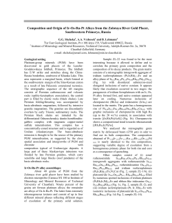
© Copyright 2026 ExpyDoc