This document is downloaded from DR-NTU, Nanyang Technological
University Library, Singapore.
Title
Author(s)
Citation
A contact-imaging based microfluidic cytometer with
machine-learning for single-frame super-resolution
processing
Huang, Xiwei; Guo, Jinhong; Wang, Xiaolong; Yan, Mei;
Kang, Yuejun; Yu, Hao
Huang, X., Guo, J., Wang, X., Yan, M., Kang, Y., & Yu,
H. (2014). A Contact-Imaging Based Microfluidic
Cytometer with Machine-Learning for Single-Frame
Super-Resolution Processing. PLoS ONE, 9(8), e104539.
Date
2014
URL
http://hdl.handle.net/10220/20408
Rights
© 2014 Huang et al. This is an open-access article
distributed under the terms of the Creative Commons
Attribution License, which permits unrestricted use,
distribution, and reproduction in any medium, provided
the original author and source are credited.
A Contact-Imaging Based Microfluidic Cytometer with
Machine-Learning for Single-Frame Super-Resolution
Processing
Xiwei Huang1, Jinhong Guo2, Xiaolong Wang1, Mei Yan1, Yuejun Kang2*, Hao Yu1*
1 School of Electrical and Electronic Engineering, Nanyang Technological University, Singapore, Singapore, 2 School of Chemical and Biomedical Engineering, Nanyang
Technological University, Singapore, Singapore
Abstract
Lensless microfluidic imaging with super-resolution processing has become a promising solution to miniaturize the
conventional flow cytometer for point-of-care applications. The previous multi-frame super-resolution processing system
can improve resolution but has limited cell flow rate and hence low throughput when capturing multiple subpixel-shifted
cell images. This paper introduces a single-frame super-resolution processing with on-line machine-learning for contact
images of cells. A corresponding contact-imaging based microfluidic cytometer prototype is demonstrated for cell
recognition and counting. Compared with commercial flow cytometer, less than 8% error is observed for absolute number
of microbeads; and 0.10 coefficient of variation is observed for cell-ratio of mixed RBC and HepG2 cells in solution.
Citation: Huang X, Guo J, Wang X, Yan M, Kang Y, et al. (2014) A Contact-Imaging Based Microfluidic Cytometer with Machine-Learning for Single-Frame SuperResolution Processing. PLoS ONE 9(8): e104539. doi:10.1371/journal.pone.0104539
Editor: Laurent Kreplak, Dalhousie University, Canada
Received April 17, 2014; Accepted July 14, 2014; Published August 11, 2014
Copyright: ß 2014 Huang et al. This is an open-access article distributed under the terms of the Creative Commons Attribution License, which permits
unrestricted use, distribution, and reproduction in any medium, provided the original author and source are credited.
Data Availability: The authors confirm that all data underlying the findings are fully available without restriction. All relevant data are within the paper.
Funding: Authors gratefully acknowledge the support from National Research Foundation Proof-of-Concept Grant (NRF2011NRF-POCO01-050) Singapore. The
funders had no role in study design, data collection and analysis, decision to publish, or preparation of the manuscript.
Competing Interests: The authors have declared that no competing interests exist.
* Email: [email protected] (HY); [email protected] (YK)
be developed for portable contact-imaging [23] based microflow
cytometer. Illuminated by incoherent light source, the direct
projected shadow or contact images of cells can be captured by the
image sensor underneath without lenses [16–22].
However, the captured images of microfluidic flowing cells are
intrinsically in low-resolution (LR) with loss of details in cell
morphology information since there is no optical lens for the
flowing samples. As shown in Fig. 1(A), one Lensless Ultra widefield Cell monitoring Array platform based on Shadow imaging
(LUCAS) system is demonstrated for cell counting application
[19]. To distinguish different cell types, the cell intensity
distribution pattern of raw LR shadow or holographic shadow
images are used [19,22]. The cells to be imaged are statically
placed in between cover slides above the image sensor array. Thus,
without continuously flowing microfluidic, the total solution
volume is limited in each test. In [17–18], a multi-frame subpixel resolving super-resolution (SR) processing is proposed with a
high-resolution (HR) cell image recovered by capturing a large
number (40 to 100) of subpixel-shifted LR cell images. As shown in
Fig. 1(B), in order to capture subpixel motions in multiple frames,
a drop-and-flow is employed to maintain the low flowing speed,
usually driven by capillary or electroosmotic flow for precise
movement control. Moreover, the storage of multiple cell images
to recover one SR image consumes huge hardware resource. Both
problems limit the throughput when counting multiple continuously flowing cells.
In this article, a contact-imaging based microfluidic cytometer is
introduced with extreme-learning-machine based single-frame SR
processing (ELM-SR) that can perform recognition and counting
Introduction
Flow cytometer has been widely deployed in biological research
and clinical diagnostics to automatically determine the count or
concentration for one or multiple types of cells [1–4]. For example,
in HIV monitoring and treatment, counting of CD4+ and CD8+
T-lymphocytes are required for antiretroviral therapy [5]. In
immunophenotyping, human peripheral blood samples are
analyzed by calculating cell concentrations for platelets, lymphocytes, and monocytes [6]. All these applications demand high
accuracy and throughput with the use of flow cytometer. A
conventional flow cytometer measurement is performed by passing
a narrow stream of cells through a focused laser beam at a rate of
thousands of cells per second. The optical signals such as forward
scattering (FSC), side scattering (SSC), fluorescent light emission
(FL) are simultaneously measured to obtain information such as
relative size, granularity or internal composition of cells. However,
because of the bulky equipment size with sophisticated optical
measurement procedure, the conventional flow cytometer is
prohibitive for point-of-care application [7–8]. In addition, flow
cytometry is traditionally relied on non-imaging technique by laser
scattering and fluorescence emission for cell identification [9–11]
and hence is lack of image information of cells [12–13].
The recent advance of microfluidics-based lab-on-a-chip
technology has introduced the possibility for the miniaturized
microflow cytometer for potable flow cytometry [9–11,14–15].
With the integration of complementary metal oxide semiconductor (CMOS) image sensor chip underneath the microfluidic
channel, microfluidics-based lensless imaging systems [16–22] can
PLOS ONE | www.plosone.org
1
August 2014 | Volume 9 | Issue 8 | e104539
Contact-Imaging Based Microfluidic Cytometer with Single-Frame ELM-SR
Figure 1. Different contact imaging systems without optical lens. (A) Static contact imaging system. (B) Microfluidic contact imaging system
with capillary flow. (C) The proposed microfluidic contact-imaging cytometer system with continuous flow: (C1) bonding process; (C2) overall system
structure.
doi:10.1371/journal.pone.0104539.g001
of-care diagnosis as well as for water quality analysis in remote and
resource-limited areas.
of cells in continuously flowing solution. The Extreme Learning
Machine (ELM) is a general suite of machine-learning techniques.
ELM theories and algorithms have been successfully used in many
applications such as bioinformatics, image processing, feature
selection, human action recognition, etc. To our best knowledge,
this paper represents the first study applying the ELM analysis to
achieve single-frame super-resolution for cell imaging. Compared
to the single-frame SR by interpolation and sharpening [24] the
pattern-recognition based SR [25–26] can recover high-frequency
(HF) components containing details for fine structures in cells. In
addition, with randomly generated weights between input layer
and hidden layer, the pattern-recognition based SR in this paper is
based on extreme learning machine (ELM) that can have much
less expensive iterative training process for on-line SR image
recovering [27]. Here is the flow of the developed single-frame
ELM-SR for the contact-imaging based microfluidic cytometer.
Static HR cell images obtained from microscope are first classified
and stored as off-line HR cell image library, which are utilized to
train an ELM-SR reference model. Note that HR cell images in
library contain the detailed internal cell structure information with
HF components. Then, the on-line single-frame SR processing is
performed by employing the ELM-SR reference model to recover
the necessary HF components from one on-line LR cell image.
The recognition and counting for different types of flowing cells
can be thereby performed accurately by only checking for the
strongest structure similarity [28] with reference to the off-line
static HR images. As such, the developed microfluidic imaging
cytometer can achieve single-cell image quality without flow rate
limitation when compared with [17–18].
We examined the performance of the prototype of the
microfluidic cytometer by measuring the absolute number of
microbeads in solution per unit time of flow, and the concentration
ratio of mixed flowing HepG2 and red-blood cells (RBCs) both at
a flow-rate of 5 mL/min. Less than 8% error is observed for the
absolute number of microbeads; and a coefficient variation of 0.10
is observed for the cell ratio when compared with a commercial
flow cytometer. The demonstrated microfluidic imaging cytometer
is thereby meaningful for rapid counting of various cells for pointPLOS ONE | www.plosone.org
Materials and Methods
System Overview
The proposed contact-imaging based microfluidic cytometer for
flowing cell recognition and counting is shown in Fig. 1(C). It
includes one PDMS microfluidic channel attached on top of a
CMOS image sensor, through which cells flow continuously. A
syringe pump continuously drives the sample solution of interest
into the channel and controls the flow rate. A conventional white
LED lamp is applied as the light source above to project flowing
microbeads or cells in the solution. The CMOS image sensor can
continuously capture shadow images underneath. The captured
digital image frames are then rapidly processed with machinelearning based single-frame SR algorithm, which can improve
resolution of shadow images such that one can recognize and
count the flowing cells.
Microfluidic Channel Fabrication
The PDMS-based microfluidic channel was fabricated by the
conventional soft-lithography [29]. The channel features were
designed in AutoCAD (Autodesk, San Rafael, CA) and then
written to a transparent mask. Then negative photoresist SU-8
(SU-8 25, Microchem, MA) was spin-coated (SCS G3P-8,
Indianapolis, IN) on a 3-inch polished silicon wafer to fabricate
the SU-8 mould. Afterwards, a volumetric ratio of 10:1 mixture of
PDMS (Sylgard 184, Dow Corning, MI) and curing agent were
poured onto the SU-8 mould. After degassing and curing, the
PDMS replica was peeled off from the master and punched on top
for inlet and outlet, which were connected with silastic laboratory
tubings to syringe pump and waste bin.
Microbead and Cell Sample Preparation
In the experiment, HepG2 cells (American Type Culture
Collection, MD) were cultured in Minimum Essential Media
(MEM) (Gibco, cat# 11095-080) supplemented with 10% fetal
2
August 2014 | Volume 9 | Issue 8 | e104539
Contact-Imaging Based Microfluidic Cytometer with Single-Frame ELM-SR
bovine serum (FBS) (Gibco, cat# 10270-106), 1 mM sodium
pyruvate (Gibco, cat# 11360-070), 0.1 mM MEM non-essential
amino acids (Gibco, cat# 11140-050), and grown at 37uC under a
5% CO2 atmosphere in a T75 flask. The harvested cells were
washed and re-suspended in phosphate-buffered saline (PBS).
(Fisher Scientific, Pittsburgh, PA). The RBCs were obtained from
National University Hospital (NUH) Singapore, also suspended in
PBS. The polystyrene microbeads of 6 mm diameter (Product#
07312, Polysciences, Warrington, PA) was selected for calibration
experiments as it is of similar size with RBC. The microbeads were
suspended in PBS. All the samples were sonicated in an ultrasonic
benchtop cleaner (Branson 2510E-DTH, Danbury, CT) for
10 minutes before pumping into the microfluidic channel to
prevent aggregation.
B Con ~f Dobj ~A= 1z Dobj =D
ð1Þ
where A is the contrast amplitude, D is the characteristic distance,
and B is the shape parameter. Guided by (1), we first discuss the
design of microfluidic channel and then CMOS image sensor.
Firstly, the protection glass of the image sensor chip was first
removed before bonding with PDMS microfluidic channel. In
addition, the microlens layer above the pixel array is removed by
treating the sensor under oxygen plasma (PDC-32G, Harrick
Plasma, Ithaca, NY) for 45 min (18 W) [17]. However, as the
developed system utilizes the continuous microfluidic flow, which
generates higher pressure to the channel wall than the one using
capillary or electroosmotic flow [16–17], a thin PDMS layer was
also spin coated on top of the sensor die. A tight PDMS-PDMS
bonding [14] is required as the process shown in Fig. 1(C1). The
spin speed of 9000 rpm is set to generate a thickness of 6 mm [30]
for PDMS. Therefore, the object distance of our system is 6 mm to
enable enough contrast for the microfluidic contact imaging. After
spin coating and baking, the surfaces of the microfluidic channel
and the image sensor were cleaned with ethanol and oxygen
plasma and are further bonded together finally as shown in
Fig. 1(C2). Note that after bonding the PDMS coated sensor chip
and the microfluidic chip, we also filled the PDMS and curing
agent mixture into the gap to encapsulate the bonding wires.
Microfluidic Cytometer Design
To build the contact-imaging based microfluidic cytometer with
higher spatial resolution, a grayscale CMOS image sensor (Aptina
MT9M032, San Jose, CA) is selected with a pixel size of
2.2 mm62.2 mm. The active sensing area is 3.24 mm(H)62.41 mm
(V) by a 1472(H)61096(V) pixel array. The hardware design is
shown in Fig. 2(C) and 2(D).
As shown in Fig. 2(A), the developed microfluidic cytometer is
based on contact imaging [16–22], where the light intensity and
contrast of one cell’s shadow image is determined by the distance
Dobj from the object to the pixel array. Note that shorter object
distance Dobj provides better contrast Con and resolution due to less
diffraction effect [23],
Figure 2. Microfluidic contact-imaging cytometer system for flowing cell detection, recognition and counting. (A) Cell shadow image
by contact imaging. (B) Captured video of flowing cells. (C) CMOS image sensor board schematic with external controls. (D) System board of the
developed microfluidic cytometer.
doi:10.1371/journal.pone.0104539.g002
PLOS ONE | www.plosone.org
3
August 2014 | Volume 9 | Issue 8 | e104539
Contact-Imaging Based Microfluidic Cytometer with Single-Frame ELM-SR
frames is determined by the sensor frame rate. Note that each
detected cell in one frame will be assigned with one unique
identification number, which means the cell count of the current
frame.
ELM-SR based Flowing Cell Recognition. As the raw
detected cell images have low resolution, SR processing needs to
be performed for better cell type recognition and further counting.
In order to resolve the problems of low flow speed and large
storage requirement, the inherent limitations of the previous
microfluidic imaging system with multi-frame SR processing [17–
18], the machine-learning based single-frame SR is developed for
the proposed contact-imaging microfluidic cytometer.
A. ELM-SR Training and Testing
As shown in Fig. 3(A), the ELM-SR includes off-line training
and on-line testing. In the training step, a reference model is
trained that can map the interpolated LR images with the HF
components extracted from the HR images from the training
library. The off-line HR training image library is first generated by
taking the grayscale HR images of cells with an inverted
microscope camera (Olympus IX71, Tokyo, Japan). For one type
of cell to generate a HR library, the cell solution is prepared and
dropped into the inlet of one microfluidic channel that is bonded
on a cover glass. This helps mimic the environment of the
microfluidic channel bonded on the CMOS image sensor. Cells
suspended in the channel can have different rotations or details in
appearance. Thus a number of typical images are taken to
generate an HR image library for one cell type under a few
appearances. Thereby, the trained reference model is more
generic (as a cell neuron) when used for the on-line SR recovery.
In the off-line training step, given the input of HR image
HRM6N, where M is the row pixel number and N is the column
pixel number, a corresponding LR image LRm6n is first generated
through bicuibic down sampling as shown in Fig. 3(A). Note that
the down sampling factor is the same as the SR enhancement
factor t, i.e., M = m6t, N = n6t. Next, the generated LR image
LRm6n is interpolated back to LR_IntM6N, which has the same
size of HRM6N but blurred and lack of HF component details. As
such, by subtracting the HR image HRM6N with the interpolated
LR image LR_IntM6N, the HF component HFM6N is obtained,
i.e.,
Moreover, to make the full use of the active pixel area, the
channel length was designed as 4.6 mm and cut in diagonal. Thus
when bonded on top of the sensor die, the rectangle microfluidic
chip was just within the die area of the bonding wire. A relative
wide channel width of 500 mm was chosen such that high
concentration of cells can flow through the channel without
clogging [31]. The height of the microfluidic channel was 30 mm,
just higher than the normal cell diameters. This ensures that the
cells flow close to the sensor surface with better projected image
contrast [17]. Besides, in order to improve the wettability of the
channel, the channel was coated with bovine serum albumin (BSA)
by flowing a 1% solution of BSA in PBS through the channel for
an hour [32].
Next, the CMOS image sensor chip was soldered on one lowcost 5.6 cm65.6 cm printed circuit board (PCB) that provides the
sensor with power supplies and digital control signals as shown in
Fig. 2(D). The data transferred from the CMOS image sensor to
PC was through a USB interface (CY7C68013-56 EZ-USB FX2,
San Jose, CA), which ensures high-speed imaging with maximum
data transfer rates of 56 Mbytes per second. The sensor working
status such as exposure time, ROI and number of frames to
capture was controlled by the status registers that can be accessed
through a two-wire serial interface, i.e., SCLK and SDATA, as the
schematic shown in Fig. 2(C). They are set through the custom
designed GUI shown in Fig. 2(B). We set 6406480 image ROI of
the sensor to capture the flowing specimens at a sensor frame rate
of ,200 frames/s (fps).
In the experiments, the microfluidic chip was connected to a
syringe pump (KDS Legato180, Holliston, MA) through silastic
laboratory tubings and samples were pumped into the microfluidic
chamber continuously at a typical flow rate of ,5 mL/min under
the illumination from a white light source (Olympus LG-PS2,
Tokyo, Japan). The thin tubing of 0.64 mm i.d. and 1.19 mm o.d.
(product no. TW-96115-04, Cole-Parmer, Vernon Hills, IL) was
used as it helps reduce dead volume and cell lost compared with
thick channel. The light source was placed 12 cm above the sensor
and the light intensity at the sensor surface was 1.5 k Lux. The
exposure time of the sensor was set ,75 ms, corresponding to 3
rows of sensor readout time. The readout LR frames were buffered
with digital image processing conducted to improve the resolution
by single-frame ELM-SR processing. As such, the developed
system can automatically recognize and count the flowing cells.
HFM|N ~HRM|N {LRM|N
ð2Þ
Contact Image Processing of Flowing Cell Frames
Digital image processing is performed to recognize and count
the cells flowing through the microfluidic channel. The processing
includes three repeating steps to all the captured frames with the
flowing cells: 1) temporal-differencing based flowing cell detection
[33–34]; 2) single-frame ELM-SR based cell type recognition [27];
and 3) cell counting of each type.
Temporal-differencing based Flowing Cell Detection. All
the flowing cells in each LR frame need to be detected first. This is
realized by the temporal-differencing based background subtraction
[33–34]. Starting from the first two frames, where the first one is the
reference (or background) frame and the second is the current (or
foreground) frame, moving cell contours in current frame is detected
by subtracting it with its previous reference frame to obtain a pixelby-pixel intensity difference. After subtraction, the regions where
the intensity differences are zero indicate no moving cells; and those
non-zero difference regions are caused by the motion of cells in the
channel, or by the addition and removal of a cell from the sensor
field-of-view (FOV). A suitable intensity threshold can be set to
identify the contours of moving cells from the background in all
frames [33]. The time-difference between each two consecutive
PLOS ONE | www.plosone.org
Based on p HF images HFM6N from the training library, the
training targeting value T is obtained which is a pNMN61 row
vector of all the pixels intensity values in HF images. Meanwhile,
the pixel intensity pattern existed in LR_IntM6N is extracted by a
363 pixel patch P(i, j) centered at pixel (i, j) of LR_IntM6N to
search through the whole image, where 1#i#M–1 and 1#j#N–
1. As such, the column vectors extracted from all patches in p
interpolated images LR_IntM6N compose the feature matrix X.
Thus, the ELM training dataset (X, T) is generated.
As such, ELM can take the input (X, T) to ELM to calculate a
row vector b containing the weights by
T~bG ðAXzB Þ
ð3Þ
where G is a sigmoid function, and A and B are randomly
generated matrix [27]. The training data with A, B and b can be
used for the ELM-SR reference model.
In the on-line testing step, when a detected LR cell image
LR’m6n is inputted, the corresponding SR image can be recovered
4
August 2014 | Volume 9 | Issue 8 | e104539
Contact-Imaging Based Microfluidic Cytometer with Single-Frame ELM-SR
Figure 3. ELM enhanced single-frame super-resolution processing flow. (A) ELM-SR processing flowchart. The training is performed off-line
to generate a reference model that can map the interpolated LR images with the HF components from the HR images; and the testing is performed
on-line to recover a SR image from the input LR image with the reference model. (B) Flowing cell recognition flowchart. The detected LR image is
processed with ELM-SR to obtain SR images according to different off-line trained models. Then, the SR images are compared with typical HR cell
images in the library with cell categorized to one type that has the largest MSSIM.
doi:10.1371/journal.pone.0104539.g003
using the same A, B and the trained b as follows. The resolution of
LR’m6n is first enhanced by t times through bicubic interpolation
to LR_Int’M6N. The same patch searching method used in the
ELM-SR training is applied to extract the feature matrix X’ from
LR_Int’M6N. Thus, one can calculate the row vector T’ that
includes the recovered HF components HF’M6N for the input LR
image LR’m6n. As such, the final SR image SR’M6N is recovered
with the sufficient HF details for cell type recognition by
PLOS ONE | www.plosone.org
0
0
0
SRM|N ~HFM|N zLR IntM|N
ð4Þ
B. Flowing Cell Recognition
Cell type recognition in the developed microfluidic cytometer is
performed after recovering the SR image SR’M6N from the input
LR image LR’m6n. The recognition process is shown in Fig. 2(B).
Assume that the samples of interest include two types of cells, two
reference models need to be trained for each type of cell. Then
5
August 2014 | Volume 9 | Issue 8 | e104539
Contact-Imaging Based Microfluidic Cytometer with Single-Frame ELM-SR
when a detected LR cell LR’m6n is inputted, two SR images,
SR1’M6N and SR2’M6N can be recovered, each corresponding to
one reference model. Afterwards, SR1’M6N and SR2’M6N are
compared with the typical HR images HR1M6N and HR2M6N in
the training libraries, where the mean structural similarity
(MSSIM/SSIM) index [28] is employed to characterize the
similarity. The SSIM is a full reference metric between 0 and 1 to
indicate the similarity between one SR image with one distortionfree reference HR image by
SSIM ðSR, HRÞ~ ð2mSR mHR Þð2sSR,HR Þ
m2SR zm2HR s2SR zs2HR
the cell count over the previous frame. As such, we add this
difference to the total cell count. By adding all the positive
differences after processing the whole series of frames, the total
number for one cell type is obtained. For other cell types, the
counting procedure is processed in the same and hence their
concentration ratio can be eventually obtained.
As such, the detection, recognition, and counting for all the
flowing cell types in the testing sample can be achieved, realizing
the function of the contact-imaging based microfluidic cytometer.
Results and Discussion
ð5Þ
To evaluate the accuracy of the developed contact-imaging
microfluidic cytometer with machine-learning for single-frame
super-resolution processing, both of the microbead solution and
mixed RBC and tumor cell solution were tested with measurement
results compared with a commercially available flow cytometer
(BD Accuri C6, NJ, US).
where mSR and mHR are the means of the SR and HR images, s2SR
and s2HR are the variances of the SR and HR images, and sSR,HR
is the covariance of the SR and HR images. It is proven to be
consistent with human eye perception compared with traditional
metric such as peak signal-to-noise ratio (PSNR) and mean
squared error (MSE) [28]. The MSSIM is the average of the
SSIMs for one SR image with all the typical HR images,
MSSIM ðSR, HRlibÞ~
K
1X
SSIM ðSR, HRk Þ
K k~1
Counting Performance Characterization
As described in the previous section, the 6 mm polystyrene
microbead solution was prepared with a concentration of
100 mL21 measured by the commercial flow cytometer. The
6 mm sample was flushed through the microfluidic channel at a
flow rate of 5 mL/min by a syringe pump. Then, a series of 640
frames were captured by the CMOS image sensor for a period of
one minute. The total number of microbeads was automatically
counted by the developed image processing algorithm. The same
process was repeated for 6 minutes, and the measured concentrations of the microbead are shown in Fig. 4. The final microbead
concentration is calculated by averaging the counting results of
each group, which was 91 uL21 with only 8% error when
compared with the result 99 uL21 by the commercial flow
cytometer.
To further evaluate the developed microfluidic cytometer, five
microbead samples of different concentrations, ranging from
,50 uL21 to ,800 uL21 were prepared. The flow rate and
imaging time were used under the same settings. As shown from
Fig. 5(A), the measurement results of the developed microfluidic
cytometer correlated well with the commercial flow cytometer
with a correlation coefficient of 0.99. Moreover, in order to assess
ð6Þ
where K is the number of typical HR images in the HR training
library. For SR1’M6N and SR2’M6N, MSSIM1 and MSSIM2 can
be calculated. Then we categorize the cell to the type that has the
stronger MSSIM.
As such, with the ELM-based single-frame SR processing, the
developed microfluidic cytometer can have much better imaging
capability to distinguish cell details in the continuously flowing
microfluidic channel.
Flowing Cell Counting. After recognizing the type for all the
detected cells flowing through the channel, the total number of
each cell type in the sample of interest can be enumerated. For one
cell type, as the cell number in each frame is already known after
the temporal-differencing based cell detection step, we subtract the
cell number of the current frame with its previous reference frame
to obtain a difference value. If this difference is larger than zero,
meaning that new cells have flown into the sensor FOV to increase
Figure 4. Comparison of concentration measurement results for 6 mm microbead solution between the developed microfluidic
cytometer and the commercial flow cytometer. The average counting result of the developed microfluidic cytometer matched well with that of
the commercial cytometer with 8% error.
doi:10.1371/journal.pone.0104539.g004
PLOS ONE | www.plosone.org
6
August 2014 | Volume 9 | Issue 8 | e104539
Contact-Imaging Based Microfluidic Cytometer with Single-Frame ELM-SR
Figure 5. Comparison of counting results of different microbead concentration solutions between the developed microfluidic
cytometer and the commercial flow cytometer. (A) Measurement results correlate well between the developed system and the commercial one
(y = 0.97x-8, correlation coefficient = 0.996). (B) The Bland-Altman analysis of the measurement results between the developed one and the
commercial one show a mean bias of 213.6 uL21, the lower 95% limit of agreement by 261.0 uL21, and the upper 95% limit of agreement by
33.8 uL21.
doi:10.1371/journal.pone.0104539.g005
the agreement between the two methods, the Bland-Altman
analysis was also performed. As the results shown in Fig. 5(B), a
systematic mean bias of 213 cells uL21 was obtained for the
developed microfluidic cytometer compared with the commercial
flow cytometer. The under counting performance was due to the
dead volume in the channel inlet/outlet as well as the cell lost and
sedimentation in the tubing.
Off-line ELM-SR Reference
For the cell recognition, HepG2 and RBC cells were used. The
resolution enhancement factor of 64 was used to improve the LR
images. Larger enhancement factor can be selected but at the
expense of longer processing time and complexity. Since current
LR pixel is 2.2 mm, after SR processing the equivalent pixel size is
reduced to 550 nm, enough for the normal cell diagnosis.
Figure 6. ELM-SR off-line training images for HepG2 and RBC cells. (A) The original HR images for HepG2 cell with two different appearances;
and the same for RBC cells. (B) The corresponding LR images. (C) The interpolated images of LR images, which cannot show HF details. (D) The
extracted HF components. The scale bar indicates 5 mm.
doi:10.1371/journal.pone.0104539.g006
PLOS ONE | www.plosone.org
7
August 2014 | Volume 9 | Issue 8 | e104539
Contact-Imaging Based Microfluidic Cytometer with Single-Frame ELM-SR
Figure 7. ELM-SR on-line testing results for HepG2 and RBC cells. The resolution is improved by 46 after ELM-SR processing. (A) The HepG2
on-line testing image and the recovered SR image. (B) The RBC on-line testing image and the recovered SR image. (C) The comparison of MSSIM for
different SR images obtained under different training models. The detected HepG2 and RBC can be correctly categorized to its type as the SR image
recovered by corresponding ELM-SR model produces a larger MSSIM when compared to each cell HR library. The scale bar indicates 5 mm.
doi:10.1371/journal.pone.0104539.g007
The off-line training HR image library of HepG2 and RBC was
first built. The raw HR images of HepG2 and RBC were taken by
the microscope camera at 640 objective, and saved into the HR
image library with the size of 48648, as shown in Fig. 6 (A1–A4).
Then, the corresponding 12612 LR images were obtained by
bicubic down sampling the HR images as shown in Fig. 6 (B1–B4).
Next, these LR cell images were interpolated back to the same size
of their original HR images, i.e., 48648. Note that the detailed
structures cannot be observed from the interpolated images
because the interpolation cannot recover the HF components, as
shown in Fig. 6 (C1–C4).
After that, the HF components for each training cell image were
obtained by subtracting the interpolated cell images from the
original HR images, such as Fig. 6 (D1–D4). As such, the training
library was generated and inputted to perform the ELM-SR
training and also obtain the reference model (A, B and b). For the
current mixed HepG2 and RBC samples, there are 30 HR images
selected for each cell type to build the training library.
recovered images show much better cell internal and edge
information that the interpolated images of Fig. 7(A3) and (B3)
cannot show. The biconcave shape of the SR image of RBC cell can
also be observed with sufficient difference from the HepG2 cell.
On-line ELM-SR Recognition and Counting
After building the off-line training image library and ELM-SR
reference models of HepG2 and RBC cells, the on-line ELM-SR
processing was performed when an LR image of HepG2 or RBC cell
was captured as shown in Fig. 7(A1) and (B1). The recovered SR
images using the corresponding trained ELM-SR models are shown
in Fig. 7(A4) and (B4), which are defined as HepG2 SRHep-Model and
RBC SRRBC-Model. It can be clearly observed that the ELM-SR
PLOS ONE | www.plosone.org
Figure 8. Commercial flow cytometer counting results for the
mixed RBC and HepG2 cells. The absolute counts of RBC and HepG2
are 1054 and 978 with the ratio of RBC/HepG2 by 51.9%:48.1% = 1.08: 1.
doi:10.1371/journal.pone.0104539.g008
8
August 2014 | Volume 9 | Issue 8 | e104539
Contact-Imaging Based Microfluidic Cytometer with Single-Frame ELM-SR
Table 1. Measured RBC and HepG2 counting results of the developed microfluidic cytometer with ELM-SR based cell recognition.
Group
RBC (#mL21)
HepG2 (#mL21)
RBC/HepG2
1
239 (54.32%)
201 (45.68%)
1.19
2
338 (50.22%)
335 (49.78%)
1.01
3
260 (53.72%)
224 (46.28%)
1.06
4
435 (52.98%)
386 (47.02%)
1.12
5
340 (55.74%)
270 (44.26%)
1.26
6
334 (49.85%)
336 (50.15%)
0.99
Mean
324 (52.60%)
292 (47.40%)
1.11
Stdev
70
72
0.11
CV
0.22
0.25
0.10
doi:10.1371/journal.pone.0104539.t001
developed an ELM-SR based SR method to recover the low
resolution of the contact images of cells.
Furthermore, different from the commercial flow cytometry that
can measure FSC and SSC signals, our contact-imaging based
cytometer has only one photo detector at the bottom, i.e., the
CMOS image sensor. Thus, it can only capture the projected
images with light source illuminating from above, similar to the
FSC. Meanwhile, the illumination light beams can be arranged
with different angles of incidence [37]. When the angle of
incidence increases to 90u, the projected images on the CMOS
sensor will be equivalent to SSC. Such a design would furnish
another strong capability of the proposed contact-imaging based
cytometer.
In addition, as for the choice of samples, RBCs and HepG2
tumor cells are among the most common cell types that
commercial flow cytometers or other cell counting systems usually
deal with. As a preliminary study, we used our prototype to
analyse and categorize these two common types of cells into their
respective groups according to the notably improved image
resolution, which cannot be achieved by the conventional on-chip
contact imaging system [36]. In the future follow-up studies, we
will further improve this platform on different cell groups with
more delicate differences in size and other cellular properties.
In addition, the SR image of HepG2 cell recovered by the RBC
trained model (HepG2 SRRBC-Model) and the SR image of RBC
SR cell recovered by the HepG2 trained model (RBC SRHep-Model)
are also shown in Fig. 7(A5) and Fig. 7(B5). One can notice large
differences when compared with the original HR images.
The MSSIMs with HepG2 library and RBC library are shown
in Fig. 7(C). The MSSIMs for HepG2 SRHep-Model and RBC
SRRBC-Model with the HR HepG2 and RBC image libraries are
0.5190 and 0.7608, respectively; and the MSSIMs for HepG2
SRRBC-Model and RBC SRHep-Model are 0.1554 and 0.2378,
respectively. The difference DMSSIM of 0.3636 and 0.5230
indicate that the SR image of both HepG2 and RBC have enough
MSSIM difference to be distinguished.
Furthermore, the ELM-SR was applied to distinguish different
flowing cell types when the cell count of each type can be
obtained. The ratio between RBC and HepG2 cells was prepared
and measured by the commercial flow cytometer with the ratio of
1.08:1 (51.9%: 48.1%) as indicated in Fig. 8. Then, the sample
was tested using the developed microfluidic cytometer at a flow
rate of 5 mL/min. As shown in Table 1, the sample was tested for
6 groups, each group for one minute. The mean RBC/HepG2
ratio is 52.60%:47.40% = 1.11:1 with the coefficients of variation
(CV) of 0.10, which matched well with the commercial flow
cytometer result (1.08:1). The CV is lower than many other
reported microfluidic cytometers (.15%) [35]. Based on the
current sample concentration, the average throughput was
3080 min21. Although the throughput is relatively low from the
commercial flow cytometry standard, it can be further improved
by increasing the sample concentration and flow rate. Moreover,
the continuous microfluidic flow developed in this paper can
enable larger volume of sample solution to be examined in each
test when compared with the drop and flow method in [17–18].
Conclusions
With the use of extreme learning machine for single-frame
super-resolution processing, one prototype of contact-imaging
based microfluidic cytometer is demonstrated for cell recognition
and counting. The developed system resolves the resolution
limitation of contact imaging by on-line image recognition based
super-resolution processing, which enables continuous high
throughput flowing cell recognition and counting. The developed
system is validated with comparison to the commercial flow
cytometer. The measured results show that the developed system
can reach less than 8% error for counting absolute number of
microbeads, and can also recognize cell ratio by 0.10 coefficient of
variation for the RBC and HepG2 cells in a mixed solution.
Discussions
The biological cells are suspended in the fluid when they are
flowing by the CMOS sensor. In addition, there is a 6 mm thick
PDMS layer coated on the sensor for chip bonding. As such,
contact imaging in this paper thereby just emphasizes a close
distance between the cell and the CMOS sensor as compared to
the conventional one using optical microscopy. It is always
desirable to minimize the distance between the cells and the sensor
in order to improve the image contrast as well as resolution
[23,36]. However, the physical distance is the fundamental
limitation of one contact imaging system with poor resolution.
Therefore, considering this first-priority limitation, we have
PLOS ONE | www.plosone.org
Acknowledgments
We are grateful for the generous help from Mr. Nishanth Venugopal
Menon, Mr. Peng Xue from SCBE NTU, Prof. Liang Yang, Mr. Yichen
Ding from SBS NTU, and Dr. Wai Chye Cheong from NUH, Singapore.
9
August 2014 | Volume 9 | Issue 8 | e104539
Contact-Imaging Based Microfluidic Cytometer with Single-Frame ELM-SR
reagents/materials/analysis tools: XH JG MY YK HY. Contributed to the
writing of the manuscript: XH YK HY. Supervised the project: MY HY.
Author Contributions
Conceived and designed the experiments: XH JG MY HY. Performed the
experiments: XH JG. Analyzed the data: XH JG XW. Contributed
References
20. Wei Q, McLeod E, Qi H, Wan Z, Sun R, et al. (2013) On-chip cytometry using
plasmonic nanoparticle enhanced lensfree holography. Scientific Reports 3:
1699.
21. Moon S, Keles HO, Ozcan A, Khademhosseini A, Hæggstrom E, et al. (2009)
Integrating microfluidics and lensless imaging for point-of-care testing.
Biosensors and Bioelectronics 24: 3208–3214.
22. Seo S, Su TW, Tseng DK, Erlinger A, Ozcan A (2009) Lensfree holographic
imaging for on-chip cytometry and diagnostics, Lab on a Chip 9: 777–787.
23. Ji H, Sander D, Haas A, Abshire PA (2007) Contact imaging: simulation and
experiment. IEEE Transactions on Circuits and Systems I 54: 1698–1710.
24. Wang T, Huang X, Jia Q, Yan M, Yu H, Yeo KS (2012) A super-resolution
CMOS imager for microfluidic imaging applications. Proceedings of IEEE
Biomedical Circuits and Systems Conference: 388–391.
25. Freeman WT, Pasztor EC (1999) Learning low-level vision. Proceedings of IEEE
International Conference on Computer Vision: 1182–1189.
26. An L, Bhanu B (2012) Image super-resolution by extreme learning machine.
Proceedings of IEEE International Conference on Image Processing: 2209–
2212.
27. Huang GB, Zhou H, Ding X, Zhang R (2012) Extreme learning machine for
regression and multiclass classification. IEEE Transactions on Systems, Man,
and Cybernetics 42: 513–529.
28. Wang Z, Bovik AC, Sheikh HR, Simoncelli EP (2004) Image quality assessment:
from error visibility to structural similarity. IEEE Transactions on Image
Processing 13: 600–612.
29. Xia Y, Whitesides GM (1998) Soft lithography. Annual review of materials
science 28: 153–184.
30. Zhang WY, Ferguson GS, Tatic-Lucic S (2004) Elastomer-supported cold
welding for room temperature wafer-level bonding. Proceedings of IEEE
International Conference on Micro Electro Mechanical Systems: 741–744.
31. Wyss HM, Blair DL, Morris JF, Stone HA, Weitz DA (2006) Mechanism for
clogging of microchannels. Physical Review E 74: 061402.
32. Bernabini C, Holmes D, Morgan H (2011) Micro-impedance cytometry for
detection and analysis of micron-sized particles and bacteria. Lab on a Chip 11:
407–412.
33. Lipton AJ, Fujiyoshi H, Patil RS (1998) Moving target classification and tracking
from real-time video. Proceedings of Fourth IEEE Workshop on Applications of
Computer Vision: 8–14.
34. Piccardi M (2004) Background subtraction techniques: a review. Proceedings of
IEEE International Conference on Systems, Man and Cybernetics 4: 3099–
3104.
35. Chen Y, Nawaz AA, Zhao Y, Huang PH, McCoy JP, Levine SJ, et al. (2014)
Standing surface acoustic wave (SSAW)-based microfluidic cytometer. Lab
on a Chip 14: 916–923.
36. Ozcan A, Demirci U (2008) Ultra wide-field lens-free monitoring of cells onchip. Lab on a Chip 8: 98–106.
37. Isikman SO, Bishara W, Zhu H, Ozcan A (2011) Optofluidic tomography on a
chip. Applied Physics Letters 98: 161109.
1. Shapiro HM (2003) Practical Flow Cytometry, 4th Edition, Wiley.
2. Givan A (2001) Flow cytometry: first principles, John Wiley & Sons.
3. Brown M, Wittwer C (2000) Flow cytometry: principles and clinical applications
in hematology. Clinical Chemistry 46: 1221–1229.
4. Gupta GP, Massague´ J (2006) Cancer metastasis: building a framework. Cell
127: 679–695.
5. Hammer SM, Eron JJ, Reiss P, Schooley RT, Thompson MA, et al. (2008)
Antiretroviral treatment of adult HIV infection. Journal of the American
Medical Association 300: 555–570.
6. Nicole B, Roederer M (2000) A practical approach to multicolor flow cytometry
for immunophenotyping. Journal of Immunological Methods 243: 77–79.
7. Myers FB, Lee LP (2008) Innovations in optical microfluidic technologies for
point-of-care diagnostics. Lab on a Chip 8: 2015–2031.
8. Zhu H, Isikman SO, Mudanyali O, Greenbaum A, Ozcan A (2012) Optical
imaging techniques for point-of-care diagnostics. Lab on a Chip 13: 51–67.
9. Wlodkowic D, Darzynkiewicz Z (2011) Rise of the micromachines: microfluidics
and the future of cytometry. Methods in Cell Biology 102: 105–125.
10. Mao X, Nawaz AA, Lin SC, Lapsley MI, Zhao Y, et al. (2012) An integrated,
multiparametric flow cytometry chip using "microfluidic drifting" based threedimensional hydrodynamic focusing. Biomicrofluidics 6: 241131–241139.
11. Huh D, Gu W, Kamotani Y, Grotberg JB, Takayama S (2005) Microfluidics for
flow cytometric analysis of cells and particles. Physiological Measurement 26:
R73–R98.
12. Yang CH, Erickson D, Psaltis D (2009) OPTOFLUIDICS: Optofluidics
enhances cytometry. BioOptics World. Available: http://www.bioopticsworld.
com/articles/print/volume-2/issue-1/features/feature-focus/optofluidicsoptofluidics-enhances-cytometry. html. Accessed 6 April 2014.
13. Schonbrun E, Gorthi SS, Schaak D (2012) Microfabricated multiple field of view
imaging flow cytometry. Lab on a Chip 12: 268–273.
14. Lin SC, Yen PW, Peng CC, Tung YC (2012) Single channel layer, single sheathflow inlet microfluidic flow cytometer with three-dimensional hydrodynamic
focusing. Lab on a Chip 12: 3135–3141.
15. McDonald JC, Whitesides GM (2002) Poly(dimethylsiloxane) as a material for
fabricating microfluidic devices. Accounts of Chemical Research 35: 491–499.
16. Heng X, Erickson D, Baugh LR, Yaqoob Z, Sternberg PW, et al. (2006)
Optofluidic microscopy—a method for implementing a high resolution optical
microscope on a chip. Lab on a Chip 10: 1274–1276.
17. Zheng G, Lee SA Lee, Yang S, Yang C-H (2010) Sub-pixel resolving optofluidic
microscope for on-chip cell imaging. Lab on a Chip 10: 3125–3129.
18. Lee SA, Leitao R, Zheng G, Yang S, Rodriguez A, Yang C-H (2011) Color
capable sub-pixel resolving optofluidic microscope and its application to blood
cell imaging for malaria diagnosis. PLOS ONE 6: e26127.
19. Su T-W, Seo S, Erlinger A, Ozcan A (2009) High-throughput lensfree imaging
and characterization of a heterogeneous cell solution on a chip. Biotechnology
and Bioengineering 102: 856–868.
PLOS ONE | www.plosone.org
10
August 2014 | Volume 9 | Issue 8 | e104539
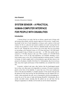
© Copyright 2026 ExpyDoc