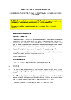
ITOH DENKI USA, INC.
HB-508S
24 VDC Hybrid Driver Card
With Built-in ZPA Logic
Rev09-0423
SPECIFICATIONS SUBJECT TO CHANGE WITHOUT NOTICE
Table of Contents
SECTION
PAGE
0
Introduction………………………………………………………………………………..
1
Features………………………………………………………………………………....... 4
2
Dimensions………………………………………………………………………………..
5
3
Basic Specifications ……………………………………………………………………...
5
4
Applicable Motorized Rollers…………………………………………………………… 6
5
3
Functions………………………………………………………………………………….. 6
5-1
5-2
5-3
5-4
5-5
5-6
5-7
5-8
5-9
5-10
5-11
5-12
5-13
5-14
5-15
5-16
5-17
5-18
ZPA function
Sensor timer
RUN holding timer………………………………………………………………………………….
Jam timer
PNP / NPN input signal
PNP / NPN output signal…………………………………………………………………………..
Sensor input
Motor run
Motor reversing …………………………………………………………………………………….
Sensor signal output
Error signal output
Synchronization signal output…………………………………………………………………….
Speed variation
Communication terminals
Power indication……………………………………………………………………………………
Connection of HB-508S
Protections
ZPA signal sentry function………………………………………………………………………...
7
8
9
10
11
12
6
Connector Specifications………………………………………………………………... 12
7
DIP Switches ……………………………………………………………………………...
8
Wiring Diagram…………………………………………………………………………… 14
9
User Controls……………………………………………………………………………... 15
10
Communication Cable……………………………………………………………………
15
11
Common Applications……………………………………………………………………
16
Revision History…………………………..………………………………………………
21
14
ITOH DENKI USA, INC.
Rev09-0423
135 Stewart Road
Hanover Industrial Estates
Hanover Township, PA 18706
SPECIFICATIONS SUBJECT TO CHANGE WITHOUT NOTICE
Page 2 of 22
Introduction
No. HB-508S – Hybrid Driver Card with Built-in ZPA Logic
HB-508S is the new generation of Built-in ZPA Logic Hybrid Driver Card. The
HB-508S has both slug (train) tote release mode and singulated tote release
mode along with sensor and jam timer functions to perfectly suit the most
common ZPA conditions.
In addition, The HB-508S provides the additional
functions of flexible zone recognizing, synchronized speed variation, stable
speed, and signal sentry function to satisfy even the most diverse and more
sophisticated automation needs.
ITOH DENKI USA, INC.
Rev09-0423
135 Stewart Road
Hanover Industrial Estates
Hanover Township, PA 18706
SPECIFICATIONS SUBJECT TO CHANGE WITHOUT NOTICE
Page 3 of 22
1 Features
• Singulated or Slug (Train) Tote Release ZPA
- Singulated Release
° As soon as the sensor in the downstream zone detects an empty zone, the sensor signal will
then activate the occupied upstream zones to transfer the tote in each zone one by one
- Slug (Train) Release
° As soon as the sensor in the downstream zone detects an empty zone, the sensor signal will
then activate the occupied upstream zones to transfer the tote in each zone simultaneously.
• Flexible Zone Recognition (Patented): Flexible Zone Recognition is enabled in Slug
Release Mode. When the tote is long enough to occupy multiple zones, the occupied
zones are recognized as one zone to maintain continuous ZPA.
• Tote Separation: Multiple totes can be separated properly by using the Singulated
Release function downstream from the Slug Release zones.
• Sensor Timer and Jam Timer Function
• Signal Sentry Function
• Single Zone Plural Motor Drive
- The HB-508S has a RUN signal output to drive multiple motors in a single zone simultaneously.
This is useful when
° The zone is longer than other zones
° The zone needs more than one motor to transfer heavier loads
• Synchronized Speed Variation
- Synchronized speed variation of multiple zones is achieved by varying the analog voltage input to
any one of the HB-508S units connected by the communication cable
• Stable Speed against Varying Load
- Applicable when
° The motor is running at nominal speed or less
° The applied load is less than the rated tangential force
• PNP or NPN Input Signal
- DIP switch selectable input type
• Simplified Wiring
- ‘plug & play’
• Reverse Polarity Protection
- HB-508S is protected in case the supply voltage wiring is reversed (+24V for 0V and 0V for +24V)
ITOH DENKI USA, INC.
Rev09-0423
135 Stewart Road
Hanover Industrial Estates
Hanover Township, PA 18706
SPECIFICATIONS SUBJECT TO CHANGE WITHOUT NOTICE
Page 4 of 22
CN5
CN4
CN1
CN7
CN3
2 Dimensions
HB-508S
CN2
(Dimensions are in mm)
•
•
•
•
•
•
•
CN1: Power connector (WAGO #734-132)
CN2: I/O control connector (WAGO #733-335)
CN3: Sensor connector (WAGO #733-363)
CN4: Communication cable connector (MOLEX #52018-8845)
CN5: Communication cable connector (MOLEX #52018-8845)
CN6: Motor connector (not used)
CN7: Motor connector (JST #S9B-XH-A)
3 Basic Specifications
• Input Voltage: 24VDC +/- 10%2
• LEDs: LED 1 lights green when powered. LED 2 lights red in case thermal overload device reacts.
• Applicable environment
- Temperature:
Between 0 – 40°C non-freezing (32 – 104°F)
- Humidity:
90% RH (no condensation)
- Atmosphere:
No corrosive gas
- Vibration:
0.5G or less
- Installation:
Indoor
4 Applicable Motorized Roller
• PM486FS/FE, PM500FS/FE, PM570ES, PM605ES series brushless DC motorized roller
ITOH DENKI USA, INC.
Rev09-0423
135 Stewart Road
Hanover Industrial Estates
Hanover Township, PA 18706
SPECIFICATIONS SUBJECT TO CHANGE WITHOUT NOTICE
Page 5 of 22
5 Functions
5-1
ZPA function
4
3
2
1
F
F
O
3
2
F
F
O
1
• The HB-508S receives the signal of the sensor from the present zone when a tote enters the zone.
• The communication cables allow signals to be exchanged between the present and adjacent zones
controlled by the HB-508Ss
- Based on the signal, the HB-508S either receives the tote into or evacuates the tote from the
present zone, depending on the occupied status in the present and adjacent upstream and
downstream zones.
• ZPA modes (single or slug release) can be
selected by the DIP switch #2-1 setting
DIP SWITCH 1
DIP SWITCH 2
(Figure 1)
• Refer to Section 7
Figure 1
5-2
4
3
2
1
F
F
3
DIP SWITCH 2
O
F
F
2
1
DIP SWITCH 1
O
• When an HB-508S is used in the last
downstream zone, the motor in the last
zone can be stopped when detecting the
presence of a tote (sensor ON) in the
present zone
• This mode can be selected by DIP switch
#2-2 (Figure 2)
• Refer to Section 7
Figure 2
Sensor timer
• The motor in the present zone will be stopped by sensor timer function when
- The motor in the present zone is running
- No tote entry into the present zone for 5 seconds after the sensor turns OFF
- No tote present in the adjacent upstream zone
• Timer setting: 6±0.5 seconds (fixed)
ITOH DENKI USA, INC.
Rev09-0423
135 Stewart Road
Hanover Industrial Estates
Hanover Township, PA 18706
SPECIFICATIONS SUBJECT TO CHANGE WITHOUT NOTICE
Page 6 of 22
5-3
RUN holding timer (VR2)
• The motor in the present zone will be stopped by the RUN hold timer when
- The motor in the present zone is running
- No tote entry in the present zone (within a certain period of adjustable time) after the sensor turns
OFF
• Time adjustable by integral potentiometer
VR2 (Figure 3)
VR1
VR2
• Adjustable range of time: Between 0.6 – 7.5
seconds
MIN
MAX
MIN
MAX
Figure 3
5-4
Jam timer
• Error signal is sent and motor is stopped when
- Present zone has a sensor ON status (presence of tote), thereby activating its motor
- No sensor status change in the zone for 4 seconds after the tote was initially detected
• Error correction – the blocking tote should be removed to switch off the sensor (i.e. clear jam)
• Jam timer setting: 4.5 seconds ( fixed)
PNP / NPN input signal
4
3
2
F
F
O
1
DIP SWITCH 2
3
2
1
DIP SWITCH 1
F
F
• Sensor, RUN, DIR (direction) input
terminals accept both NPN and PNP signals
by receiving the signal through a photo
coupler
• NPN or PNP input signal is selected by DIP
switch #1-1 (Figure 4)
• ON – PNP, OFF – NPN
• Refer to Section 7
O
5-5
Figure 4
ITOH DENKI USA, INC.
Rev09-0423
135 Stewart Road
Hanover Industrial Estates
Hanover Township, PA 18706
SPECIFICATIONS SUBJECT TO CHANGE WITHOUT NOTICE
Page 7 of 22
PNP / NPN output signal
4
3
2
F
F
F
F
O
1
DIP SWITCH 2
3
2
DIP SWITCH 1
O
• Sensor, synchronization and error output
signal can be either PNP or NPN open
collector
• PNP or NPN output signal is selected by
DIP switch #1-2 (Figure 5)
• Refer to Section 7
1
5-6
Figure 5
4
3
2
F
F
F
F
O
1
DIP SWITCH 2
3
2
1
DIP SWITCH 1
O
• Sensor signal output and synchronization
signal output are alternatives and can be
selected by the DIP switch #1-3 (Figure 6)
• In case both signal outputs are needed at
the same time, the sensor signal output can
be retrieved from the sensor terminal of
CN3
• Refer to Section 7
Figure 6
5-7
Sensor input (CN3)
• Sensor and sensor alarm outputs should be set ON when detecting tote
5-8
Motor run (CN2)
4
3
2
1
F
F
O
3
2
F
F
O
1
• The motor will be activated and stopped automatically by ZPA logic functions (which depend on the
sensor status in the present and adjacent upstream and downstream zones)
• The motor is subject to ZPA logic when the
input terminal is open
DIP SWITCH 1
DIP SWITCH 2
• The motor will be forcibly activated by
closing the input terminal, but will not
override the ZPA logic
• The motor will forcibly run as long as the
RUN input is closed when DIP switch 2-4 is
ON (Figure 7)
Figure 7
ITOH DENKI USA, INC.
Rev09-0423
135 Stewart Road
Hanover Industrial Estates
Hanover Township, PA 18706
SPECIFICATIONS SUBJECT TO CHANGE WITHOUT NOTICE
Page 8 of 22
Motor reversing (CN2)
3
2
1
F
F
O
3
2
F
F
O
1
• DIR (direction) signal input will
- Cause the HB-508S connected to CN5 be upstream
- Cause the HB-508S connected to CN4 be downstream
- Reverse all the motors in the adjacent upstream and downstream zones
° Adjacent HB-508S must be linked by the communication cable
• Communication cable carries DIR signal
° 30 zones maximum can simultaneously reverse direction
° DIR signal can be inputted to any one zone to change all zones
° DIR signal inputted – the FS series motor will rotate CW (from lead side)
• Single motor direction can be reversed by
using DIP switch #2-3 (Figure 8)
DIP SWITCH 1
DIP SWITCH 2
• Motor turning direction of FS and FE units
differ
• DIP #2-3 ON, FE units rotate CCW; OFF,
FE units rotate CW
• DIP #2-3 OFF, FS units rotate CCW; ON,
FS units rotate CW
Figure 8
4
5-9
5-10 Sensor signal output (CN2)
4
3
2
F
F
F
F
O
1
DIP SWITCH 2
3
2
1
DIP SWITCH 1
O
• Signal sensor output of the present zone is
from CN2 terminal 4, when the DIP switch
#1-3 is OFF
• Output transistor will be ON, when detecting
tote (sensor ON) (Figure 9)
Figure 9
5-11 Error signal output (CN2, LED 2)
• Error signal output terminal in CN2 terminal 5 will emit a signal (high) if all the HB-508S in the zones
linked through the communication cables are in normal status
• Output transistor is ON in normal status (to allow error output in case of fuse failure)
• Failed (troubled) zone can easily be identified by LED 1 (lights green when powered – normal status)
and LED 2 (lights red in case of error) on individual HB-508S
• Error signal (low) for any of the following failures
- Reaction of thermal overload device either circuitry (> 85°C) or motor ( > 105°C) (motor continues
to run with lowered output, lighting LED 2 and maintaining ZPA)
- Jam timer setting time over (stops motor to cease ZPA, lighting LED 2)
ITOH DENKI USA, INC.
Rev09-0423
135 Stewart Road
Hanover Industrial Estates
Hanover Township, PA 18706
SPECIFICATIONS SUBJECT TO CHANGE WITHOUT NOTICE
Page 9 of 22
5-12 Synchronization signal output (CN2)
4
3
2
1
F
F
O
3
2
F
F
O
1
• Synchronization signal is discharged when the motor in the present zone starts running.
- This signal enables synchronized motor operation in multiple zones which are linked by
communication cables to other HB-508S
• This also allows the synchronized operation of the multiple motors in the same zone (plural motor
drive)
• CN2 terminal #4 will be the synchronization
DIP SWITCH 1
DIP SWITCH 2
signal output terminal if the DIP switch #1-3
is set ON (Figure 10)
Figure 10
• Transistor of open collector output is ON when running (max 25mA)
5-13 Speed variation (VR1)
• Motor speed can be varied by turning the
integral potentiometer VR1 (Figure 11)
VR1
MIN
VR2
MAX
MIN
MAX
Figure 11
• Speed of the motors in all zones can be simultaneously varied by
- Inputting an analog voltage to the CN2 #3 terminal of any one HB-508S
- Adjusting the voltage input (0-10V)
- Having all the HB-508S linked by communication cables
- Setting the integral potentiometer to minimum
• 20mA current is consumed at 10V
- Therefore 400mA capacity is needed to control 20 zones.
5-14 Communication terminals (CN4, CN5)
• Allows transmission and communication
- Of signals
° Sensor
° Error
° Transfer direction
° External speed variation
° Motor drive status
- Between present, upstream, and downstream zones
ITOH DENKI USA, INC.
Rev09-0423
135 Stewart Road
Hanover Industrial Estates
Hanover Township, PA 18706
SPECIFICATIONS SUBJECT TO CHANGE WITHOUT NOTICE
Page 10 of 22
5-15 Power indication (LED 1)
• Lights green when powered (+24V and 0V are supplied to CN1)
5-16 Connection of HB-508S
Present (HB508S) zone to non-HB-508S zones or HB-508S zones without communication cable
4
3
2
1
F
F
O
3
2
1
F
F
O
Figure 12
4
3
2
1
F
F
F
F
O
3
2
DIP SWITCH 2
O
1
DIP SWITCH 1
Figure 13
4
3
2
F
F
O
1
DIP SWITCH 2
3
2
DIP SWITCH 1
1
Present zone to downstream zone
• Case 2 – Last Downstream Zone
setting
• Signal input from downstream zone to
input terminal CN2 #1
• Totes accumulate to present zone in
normal ZPA fashion
• Tote will not evacuate present zone
until downstream zone signals it to
RUN forcibly
• DIP settings (Figure 14)
DIP SWITCH 2
F
F
Present zone to downstream zone
• Case 1 – Normal Zone setting
• Signal input from downstream zone
(downstream zone clear) to input
terminal CN2 #1
• Normal ZPA Logic
• Tote automatically evacuates when
downstream zone is clear
• DIP settings (Figure 13)
DIP SWITCH 1
O
Present zone to upstream zone
• Tote entry (present zone) through
forcible RUN signal from upstream
zone to input terminal CN2 #1
• Sensor output to prevent tote collision –
signals upstream zone if present zone
is occupied – through output terminal
CN2 #4
• Logic designed to prevent tote collision
• DIP settings (Figure 12)
Figure 14
5-17 Protections
• Thermal Overload Device: Reacts either at 105°C (2 21°F) inside motor or 85°C (185°F) on PCB to
lower the motor output to prevent motor overheat and burnout. When this reacts, LED will also light
red.
• Current Limiter: is set at 3A maximum (motor locking current is 3A)
ITOH DENKI USA, INC.
Rev09-0423
135 Stewart Road
Hanover Industrial Estates
Hanover Township, PA 18706
SPECIFICATIONS SUBJECT TO CHANGE WITHOUT NOTICE
Page 11 of 22
5-18 ZPA Signal Sentry function
4
3
2
F
F
F
F
O
1
DIP SWITCH 2
3
2
1
DIP SWITCH 1
O
• Forcible STOP
• Tote is received from upstream zone
• Tote in present zone does not evacuate
while receiving a signal at input
terminal CN2 #1
• Normal ZPA logic operates while there
is no input signal
• DIP settings (Figure 15)
Figure 15
6 Connector Specifications
6-1
CN1 Power Connector (2P) – Included
1
2
6-2
WAGO #734-102
For control cable side
Wire AWG28-14
Input 100W or over
CN2 Control Connector (5P) – Not Included
1
2
3
4
5
6-3
Wago #734-132
For driver side
+24VDC
0V
WAGO #733-335
For driver side
Terminal input
DIR input
Speed variation voltage input
Sychronization/sensor output
Error output
WAGO #733-105 (option)
For control cable side
Wire AWG28-20
Input 0-10V (external speed variation only)
Input +24V or 0V (all others)
Output: Open collector
(Max 25mA DC)
CN3 Sensor Connector (3P) – Included
1
2
3
WAGO #733-363
For driver side
+24VDC
Sensor
0V
WAGO #733-103
For control cable side
Wire AWG28-20
High – Active
ITOH DENKI USA, INC.
Rev09-0423
135 Stewart Road
Hanover Industrial Estates
Hanover Township, PA 18706
SPECIFICATIONS SUBJECT TO CHANGE WITHOUT NOTICE
Page 12 of 22
6-4
CN4 Communication Connector (8P) – Not Included
1
2
3
4
5
6
7
8
6-5
Hirose #TM10P-88P equivalent (Option)
For control cable side
Wire AWG26 equivalent
CN5 Communication Connector (8P) – Not Included
1
2
3
4
5
6
7
8
6-6
MOLEX #52018-8845
For driver side
Sensor signal output
Sensor signal input
Speed variation
Error signal
Drive input
Drive output
Direction signal
GND
MOLEX #52018-8845
For driver side
Sensor signal input
Sensor signal output
Speed variation
Error signal
Drive output
Drive input
Direction signal
GND
Hirose #TM10P-88P equivalent (Option)
For control cable side
Wire AWG26 equivalent
8P
CN7 Motor Connector (9P) – Included with Power Moller
1
2
3
4
5
6
7
8
9
JST #S9B-XH-A 9P
For driver side
GND (gray)
+12V (blue)
Motor phase U (red)
Motor phase V (white)
Motor phase W (black)
Hall sensor U (violet)
Hall sensor V (orange)
Hall sensor W (green)
Thermister (light blue)
JST #XHP-9
Mounted to the motor cable
Pressured connection terminal
#DF3-22SCF (supplied in reel)
Wire AWG28-22 exept AWG24-22 used for
motor phases
* brake option is customized
ITOH DENKI USA, INC.
Rev09-0423
135 Stewart Road
Hanover Industrial Estates
Hanover Township, PA 18706
SPECIFICATIONS SUBJECT TO CHANGE WITHOUT NOTICE
Page 13 of 22
7 DIP Switches
DIP
Sw 1
SW #
Function
Setting
1
2
PNP/NPN input signal switch
PNP/NPN output signal switch
Synchronization or sensor output
switch
Singulated or slug release mode
switch
ON – PNP, OFF – NPN
ON – PNP, OFF – NPN
ON – Synchronization output
OFF – Sensor signal output
ON (ZP1) – slug (train) release mode
OFF (ZP2) – singulated release mode
ON (ZB)– Normal zone
OFF (ZE)– The last downstream zone
ON – FE unit
OFF – FS unit
ON – Foricble RUN
OFF – Forcible Stop
3
1
DIP
Sw 2
2
Last downstream zone setting
3
Motor setting FS or FE
4
Forcible RUN or Forcible Stop
switch
Standard
Setting
ON
ON
ON
ON
ON
ON
ON
8 Wiring Diagram
ITOH DENKI USA, INC.
Rev09-0423
135 Stewart Road
Hanover Industrial Estates
Hanover Township, PA 18706
SPECIFICATIONS SUBJECT TO CHANGE WITHOUT NOTICE
Page 14 of 22
9 User Controls
CN2
VR2
4
VR1
5
4
3
1
DIP SWITCH 2
F
F
O
3
2
F
F
O
1
DIP SWITCH 1
INPUT
ZE
DIR
ZP2
1
NPN NPN SEN
SPE RUN
IN
IN
ED TIM
FS STOP VR1 VR2
2
IN
RUN
Vin
IN
OUT OUT
FE
3
ZB
2
IN
ZP1
OUT A
PNP PNP SYN
ERR
DEFAULT HB-508S CARD SETTINGS
MIN
MAX
MIN
MAX
10 Communication Cable
PIN SEQUENCE
1
8 7 6 5 4 3 21
8 7 6 5 4 3 21
1
CATEGORY 5 CABLE
8-PIN MALE CONNECTOR - RJ-45
STRAIGHT THROUGH WIRING
EACH MALE CONNECTOR IS WIRED THE SAME
ITOH DENKI USA, INC.
Rev09-0423
135 Stewart Road
Hanover Industrial Estates
Hanover Township, PA 18706
SPECIFICATIONS SUBJECT TO CHANGE WITHOUT NOTICE
Page 15 of 22
11 Common Applications
• The following pages illustrate
- Common applications of the HB-508S
- DIP switch settings for HB-508S
- General wiring of the HB-508S
• Common applications of the HB-508S are
- Basic Setup (Page 17)
° NPN input from photo-eye
° HB-508S linked by communication cables
° HB-508S in the last downstream zone is set for Zone End (ZE)
- Infeed Conveyor Setup (Page 18)
° Similar to basic setup
° Except it uses photo-eye
• Setup at the end of the upstream conveyor
• To forcibly RUN the rollers in the first zone
- Discharge Conveyor Setup
° These are just two basic discharge setups
• PE (photo-eye) discharge setup (Page 19)
o HB-508S in last downstream zone
Set to ZB
Set to STOP
Receives signal from photo-eye to forcibly STOP
o Normal ZPA logic operation
• PLC discharge setup (Page 20)
o HB-508S in last downstream zone
Set to ZE
Set to RUN
Receives signal from PLC to forcibly RUN
o Operation
Normal ZPA until last downstream zone
Tote waits in final zone
° Until HB-508S receives command to RUN from PLC
ITOH DENKI USA, INC.
Rev09-0423
135 Stewart Road
Hanover Industrial Estates
Hanover Township, PA 18706
SPECIFICATIONS SUBJECT TO CHANGE WITHOUT NOTICE
Page 16 of 22
One Zone
2
F
F
1
O
2
F
F
IN
ZP1
HB-508S
PNP PNP SYN
ZP2
F
F
3
4
F
F
3
1
5
2
IN
FS STOP
IN
ZB
ZE
IN
FE RUN SPE RUN
ED TIM
VR1 VR2
User Controls (default)
HB-508S
Zone Beginning
1
0 VDC
+24 VDC
SPECIFICATIONS SUBJECT TO CHANGE WITHOUT NOTICE
EXAMPLE - ZPA Conveyor Setup
2
Flow
2
4
FS Power Moller - Singulated - NPN Photoeye - Zone End
2
Zone End
HB-508S
OUT OUT
INPUT
HB-508S
IN
CN2
DIR
4
VR2
OUT A
1
O
Idler Roller
NPN NPN SEN
VR1
1
3
MAX
2
4
DIP SWITCH 2
MIN
Vin
3
DIP SWITCH 1
MAX
4
2
5
Communication Cable
MIN
ERR
2
2
F
F
1
5
3
2
F
F
4
3
5
2
1
3
1
O
3
4
3
Photo Eye
Power Moller
HB-508S
4
O
3
2
F
F
1
O
5
2
F
F
1
O
1
O
3
3
1
F
F
3
4
Power Leads
2
F
F
Page 17 of 22
135 Stewart Road
Hanover Industrial Estates
Hanover Township, PA 18706
Rev09-0423
1
O
1
O
1
O
3
3
4
ITOH DENKI USA, INC.
One Zone
1
O
2
F
F
F
F
4
Flow
HB-508S
2
PNP PNP SYN
OUT OUT
2
3
1
Zone Beginning
HB-508S
2
IN
ZP1
ZE
IN
ZB
IN
FS STOP
IN
FE RUN SPE RUN
ED TIM
VR1 VR2
Infeed
Conveyor
0 VDC
+24 VDC
To Photo Eye
User Controls (default)
ZP2
SPECIFICATIONS SUBJECT TO CHANGE WITHOUT NOTICE
EXAMPLE - ZPA Conveyor Setup
3
FS Power Moller - Singulated - NPN Photoeye - Zone End - Infeed Conveyor
HB-508S
2
F
F
4
Idler Roller
1
3
1
O
3
2
F
F
Zone End
HB-508S
4
Photo Eye
Power Moller
IN
CN2
DIR
1
VR2
1
5
VR1
OUT A
3
NPN NPN SEN
DIP SWITCH 2
4
5
2
DIP SWITCH 1
MAX
2
3
MIN
Vin
3
4
MAX
ERR
1
3
1
O
Communication Cable
MIN
5
2
HB-508S
4
4
3
2
5
Power Leads
3
3
2
F
F
1
O
3
Page 18 of 22
135 Stewart Road
Hanover Industrial Estates
Hanover Township, PA 18706
Rev09-0423
2
F
F
O
3
2
F
F
1
O
5
2
F
F
4
2
F
F
4
1
O
1
F
F
1
O
1
O
1
O
3
3
4
INPUT
ITOH DENKI USA, INC.
2
F
F
1
2
F
F
O
HB-508S
IN
F
F
2
F
F
3
1
Zone Beginning
HB-508S
IN
FE RUN SPE RUN
ED TIM
VR1 VR2
IN
FS STOP
VR2
0 VDC
+24 VDC
CN2
SPECIFICATIONS SUBJECT TO CHANGE WITHOUT NOTICE
EXAMPLE - ZPA Conveyor Setup
2
4
FS Power Moller - Singulated - NPN Photoeye - PE Discharge Conveyor
3
4
Flow
1
O
Discharge
Conveyor
HB-508S
ZE
VR1
OUT A
2
4
User Controls (default)
IN
ZB
ZP2
ZP1
3
ERR
HB-508S
PNP PNP SYN
5
MAX
INPUT
1
3
2
5
Idler Roller
OUT OUT
DIP SWITCH 2
MIN
DIR
4
5
2
Photo Eye
Power Moller
IN
NPN NPN SEN
DIP SWITCH 1
4
4
Communication Cable
MAX
1
4
MIN
2
2
3
Vin
3
3
2
F
F
1
O
5
2
F
F
F
F
1
3
1
O
3
4
3
4
3
2
1
O
1
O
To Photo Eye
One Zone
3
4
HB-508S
3
3
2
F
F
5
2
F
F
1
O
Power Leads
2
F
F
Page 19 of 22
135 Stewart Road
Hanover Industrial Estates
Hanover Township, PA 18706
Rev09-0423
1
O
1
O
1
O
3
1
ITOH DENKI USA, INC.
1
2
F
F
O
HB-508S
IN
F
F
2
F
F
3
1
Zone Beginning
HB-508S
IN
FE RUN SPE RUN
ED TIM
VR1 VR2
IN
FS STOP
VR2
0 VDC
+24 VDC
CN2
SPECIFICATIONS SUBJECT TO CHANGE WITHOUT NOTICE
EXAMPLE - ZPA Conveyor Setup
2
4
FS Power Moller - Singulated - NPN Photoeye - PLC Discharge Conveyor
3
4
Flow
HB-508S
1
O
Discharge
Conveyor
HB-508S
ZE
VR1
OUT A
2
4
User Controls (default)
IN
ZB
ZP2
ZP1
3
ERR
2
F
F
PLC
0V
PNP PNP SYN
5
MAX
INPUT
1
3
2
5
Idler Roller
OUT OUT
DIP SWITCH 2
MIN
DIR
4
5
2
Photo Eye
Power Moller
IN
NPN NPN SEN
DIP SWITCH 1
4
4
Communication Cable
MAX
1
4
MIN
2
2
3
Vin
3
3
2
F
F
1
O
5
2
F
F
F
F
1
3
1
O
3
4
3
4
3
2
1
O
1
O
To PLC
One Zone
3
4
HB-508S
3
3
2
F
F
5
2
F
F
1
O
Power Leads
2
F
F
Page 20 of 22
135 Stewart Road
Hanover Industrial Estates
Hanover Township, PA 18706
Rev09-0423
1
O
1
O
1
O
3
1
ITOH DENKI USA, INC.
Installation Precautions – IMPORTANT, PLEASE READ BEFORE INSTALLATION
Precaution
Action
Reason
Multiple power
supplies
0V line of all power supplies on
the same conveyor line
(powering the card/rollers, &
controls) need to be physically
linked together.
This completes the signal path from
one section of the conveyor (powered
by a power supply) to the adjacent
section of conveyor (powered by
another power supply) and allows for
proper communication through the
cable and external interfaces.
Voltage drop
across the power
bus
Use suitable gauge wire in
relation to distance and current
draw to prevent voltage drop.
When running long distances from a
DC power supply, the voltage drop
during motor operation across the
power bus may be significant (may
drop below 15V!). If there is a large
enough drop in voltage, the roller(s)
may behave in a strange manner. In
order to prevent this, a larger gauge
wire must be used.
Operating DC voltage is 24V
±10%
Grounding
Ensure the control card is
securely grounded to the
conveyor frame. The conveyor
frame should also be at the same
potential reference as earth
ground. Standard grounding
practices should be followed.
Static discharge may interfere and
damage internal components.
Electrical
24V DC ±10%
4A maximum current limiter
(motor lock is 4A)
Diode protection for miswiring
Sensor power short circuit
protection
5A fuse for power supply
protection
Improper power will damage the card.
The motor/card should not be subject
to locked conditions repeatedly.
Internal fuse is not replaceable. If the
fuse has blown, more serious damage
has occurred within the card/motor.
Environment
Ambient temperature is
32~104°F
Ambient humidity is < 90%RH
Atmosphere has no corrosive gas
Vibration is < 0.5G
Indoor use only
Extreme environmental variables may
cause poor or no performance and
damage the card.
Over-speeding
Over-speeding of the roller’s noload speed by more than 50%
may cause damage.
Back EMF will be generated.
ITOH DENKI USA, INC.
Rev09-0423
135 Stewart Road
Hanover Industrial Estates
Hanover Township, PA 18706
SPECIFICATIONS SUBJECT TO CHANGE WITHOUT NOTICE
Page 21 of 22
Revision History
Revision Number
A-12.19.02
A-06.30.03
A-10.07.03
A-10.27.03
05-0816
05-0822
08-0115
09-0423
Change
Initial document
Layout restructured, wording clarified
Added: cover page; table of contents; communication cable drawing; common applications
section; standard configuration drawing; infeed configuration drawing; and 2 discharge
configuration drawings
Updated VR2 drawings to match default setting
Updated photograph and dimensional drawing to reflect heat-sink implementation
Revision number format changed
Updated speed variation information (VR1)
Added revision history table
Adjusted page numbers and referenced page number throughout document
Added precautions
ITOH DENKI USA, INC.
Rev09-0423
135 Stewart Road
Hanover Industrial Estates
Hanover Township, PA 18706
SPECIFICATIONS SUBJECT TO CHANGE WITHOUT NOTICE
Page 22 of 22
© Copyright 2026 ExpyDoc