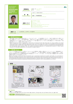
P16 静電浮遊法を用いた新たな熱物性計測法の開発(Ⅱ) ○梅山浩樹,正木匡彦(芝浦工大) Development of a New Method of Thermophysical Properties Measurements by using the Electrostatic Levitator (Ⅱ) Hiroki UMEYAMA , Tadahiko MASAKI (Shibaura Institute of Tech.) 1. Introduction 2. Experimental Apparatus The purpose of this study is the development of a new method for measuring thermophysical properties by using the electrostatic levitator. The electrical property, such as the electrical resistivity, is one of the most important properties of metallic melts at the extremely high temperature. Nevertheless, the experimental data with sufficient accuracy have not been provided because of the experimental difficulties. The levitation technique together with the sample rotation by the induced magnetic field can be applied to the measurement of electrical resistivity in the previous study1). The rotation speed of levitated sample is the important factor for the measurement of electrical resistivity by this method, and it is measured by the observation of time dependency of reflectivity of rotating sample. However, in the case of sample with clean surface, the angular dependence of reflectivity of rotating sample is almost constant. It makes difficult to the measurement of electrical resistivity. In this study, we develop the new method for the measurement of rotation speed of levitating sample by using the electrical static levitation method together with YAG laser heating. Four electromagnets were fixed around the sample to apply the rotational force of levitated sample. The sample was heated by CO2 Lasers which were irradiated from the horizontal direction. The sample temperature was measured by single color pyrometers from the horizontal direction. A YAG laser was installed to the system to make the pulse heating to the levitated sample in order to make a small heated area at the sample surface. When the heated area of rotated sample faced to the pyrometer, the pulse-like signal can be detected in the time dependence of sample temperature. The frequency of sample rotation can be measured from the interval of the pulse-like signals. The schematic figure of this system was shown in Fig. 1. The result will be presented in the poster session. References 1) W.K.Rhim, Takehiko Ishikawa : Rev.Sci. Instrum., 69(10) (1998), 3628. − 68 − P17 液膜内 thermocapillary 流れの方向性に対する体積比の影響に関する数値解析 ○山本卓也,高木洋平,岡野泰則 (大阪大学) Numerical Study for the Effect of Volume Ratio on the Direction of Thermocapillary Flow in a Liquid Film Takuya YAMAMOTO, Youhei TAKAGI, Yasunori OKANO (Osaka Univ.) 1. Introduction Dr. D. Pettit conducted a series of experiment called as ‘Saturday Morning Science’ in 2003 onboard International Space Station (ISS)1). One of the experiments was about thermocapillary flow in a water film sustained in a circular wire. In this experiment, the developed flow was toward the heated area, which was contrary to the usually observed thermocapillary flow. To investigate the flow in the water film, a numerical simulation was carried out. In this research, we focused on the free surface shapes. 2. Numerical Methods The governing equations are Navier-Stokes, continuity, and energy equations. The details of the numerical methods are shown in our previous paper2), and the numerical simulation was conducted by OpenFOAM. volume ratio. Therefore, numerical results suggested that experimental water film was convex shape. Acknowledgement This research work was financially supported by Grant-in-Aid for Scientific Research (B) (Grant No. 22360343 and No. 25289087) from Ministry of Education, Culture, Sports, Science, and Technology of Japan, and supported partly by Collaborate Research Program for Young Scientists of ACCMS and IIMC, Kyoto University. 1) D. Pettit, ‘Saturday Morning Science Videos’ (2003). 2) T. Yamamoto, Y. Takagi, Y. Okano and S. Dost: Phys. Fluids, 25 (2013) 082108. (a) (b) 3. Results The path lines are shown in Fig. 1. In the concave water film, the developed flow was toward the center of the water film (inward flow). However, in the convex water film, the developed flow was toward heated area (outward flow). Finally, we found the direction of thermocapillary flow depended on the Fig. 1 Path lines at 2 s: (a) in a concave water film and (b) in a convex water film. − 69 − P18 宇宙船における新しい消火方法:吸い込み消火法に関する諸検討 ○薄木太一,中村祐二(北海道大学),若月薫(消防研究センター) Novel Extinction Method in Spacecraft: Evaluation for The Vacuum Extinction Method ○Taichi USUKI, Yuji NAKAMURA (Hokkaido Univ), Kaoru WAKATSUKI (Nat’l Res Inst of Fire and Disaster) The objective of this research is to develop a novel extinction method that may improve existing method used in spacecraft. The existing method of ejecting inert gasses to fire source has the potential problem of spreading fire products(including toxic gas) in all directions due to the ejecting extinguisher1). To solve this problem, we propose a novel fire-extinguishing method named as VEM (Vacuum Extinction Method). The concept of VEM is shown in Fig.1. In VEM, toxic gases are sucked up and insulated in vacuuming box which acts as inducing vacuuming flow. Vacuuming flow contributes to extinction through three factors. First is increasing flow velocity that removes fuel from burning materials. Second is cooling burning materials that prevents rising volatilized fuel. Third is vacuuming materials. The performance of VEM had been investigated using a cable with copper or iron core and polymer sheath shown in Fig.2. Polymer sheath is frequently used as insulator of the cable and can be the fire source in spacecraft2). In this study, the extinction mechanism and condition in VEM have been researched. Main experimental parameters are vacuuming flow rate and distance between end of the vacuuming pipe and center of the cable. Acknowledgement This research is supported by Grant-in-Aid for Challenging Exploratory Research, The Ministry of Education, Science, Sports and Culture (# 25560160, PI: Y. Nakamura) and has been conducted as a part of FY24-25 JNES contracted work monitored by Mr. Tsuchino and Ishibashi. References 1) NASA, fire prevention in space, http://www.nasa.gov/ missions/shuttle/f_fireprevention html 2) R. Friedman: Fire Safety in the Low-Gravity Spacecraft Environment, WU-962-22-00-00(1999) − 70 − Vacuuming pipe Vacuuming direction Vacuuming pipe Vacuum box Flame Vacuuming burning Fire effluent materials Burning materials Fig. 1 The concept of VEM Fig. 2 VEM in cable fire P19 非共溶性混合媒体を用いた高性能冷却システムに関する研究 ○山崎優佑,福山雄太,金澤昇平,大西俊輔,大田治彦(九州大学) A Study of High Performance Heat Transport System by using Immiscible Liquid Mixture Yusuke YAMASAKI, Yuta FUKUYAMA, Shohei KANAZAWA, Shunsuke ONISHI, Haruhiko OHTA (Kyushu Univ.) 1. Abstract Recent increase in heat flux density semiconductors under development requires an ability to handle a large amount of waste heat. Heat transport system using flow boiling attract much attention because of its superior heat transfer characteristics. Furthermore, the use of immiscible liquid mixture prevents the excessive growth of bubbles generated from the heating surface. Its heat transfer characteristics in pool boiling are investigated. The overshoot of surface temperature at the boiling initiation remains at small value by using immiscible liquid mixture. This is because the subcooling of the morevolatile liquid remains small under the weak compression by the low vapor pressure of the less-volatile component. Furthermore, the equilibrium temperature of the immiscible mixture is much lower than the saturation temperature of the pure less-volatile liquid under the same pressure. In the existing researches, boiling of non-azeotropic miscible mixtures are performed to clarify the heat transfer deterioration due to mass diffusion resistance or the enhancement due to Marangoni effect, while the number of investigation concerning the immiscible mixtures is very limited. Especially, there is almost no investigation on heat transfer characteristics for immiscible mixture under flow boiling conditions. In the present study, to obtain fundamental knowledge about the interfacial behaviors including those between two component liquids and corresponding heat transfer characteristics, the experiment are conducted by using a test loop designed for the steady-state circulation of immiscible mixtures at a desired flow rates of both components as shown in Fig.1. − 71 − Fig.1 Outline of test loop P20 微小重力環境下での TLZ 法による SiGe 結晶成長プロセスの 数値シミュレーションに関する研究 ○住岡沙羅,阿部敬太,杉岡健一,久保正樹,塚田隆夫(東北大学大学院工学研究科), 木下恭一,荒井康智,稲富裕光(宇宙航空研究開発機構) A Numerical Study on TLZ Crystal Growth Process of SiGe under Microgravity Environment Sara SUMIOKA, Keita ABE, Ken-ichi SUGIOKA, Masaki KUBO, Takao TSUKADA (Tohoku Univ.), Kyoichi KINOSHITA, Yasutomo ARAI, Yuko INATOMI (JAXA) 1. Introduction 3. Results and discussion The first travelling liquidus-zone (TLZ) growth experiment for a SiGe crystal with homogeneous composition was performed using a gradient heating furnace on board the JEM “Kibo” in the ISS this March. In this work, a mathematical model for transport phenomena in the TLZ crystal growth of SiGe was developed to understand the details of the TLZ crystal growth process of SiGe in microgravity, especially the Ge (or Si) concentration distributions in the crystal. Then, the experimental results in the ISS were explained using this model. Fig. 1(a) shows the calculated thermal field in the TLZ furnace, Ge concentration field in the melt and melt/SiGe crystal interface shape after 7430 min of growth. Fig. 1(b) shows the calculated axial concentration profile of Ge along the center line of the crystal as well as the experimental one. Ge concentration is almost constant in the crystal, and the present numerical model could explain the experimental results well. 1410 2. Mathematical model Si feed The self-made numerical model based on the assumption that the system is axial symmetric can predict the velocity field in the melt, the thermal fields in the melt, crystal and crucible, Ge concentration fields in the melt and crystal, and the melt/crystal interface shapes. The boundary conditions for temperature at the outer wall of the crucible in the model were determined by a global analysis of heat transfer in the TLZ furnace using a commercial software FLUENT. SiGe melt Ge (at.%) 80 (b) Ge (at.%) (a) Temp. (K) Crucible 70 50 30 0 Experimental results Numerical results 6 12 Growth distance (mm) 18 SiGe crystal Si seed − 72 − 1285 77 Fig. 1 (a) Thermal field in the furnace (left side) and Ge concentrationfield in the melt (right side) at 7430 min. (b) Axial concentration profiles of Ge. P21 Ge および Ge-1at%Si の過冷融液からの結晶化のカイネティクス ○佐藤広大,米山覚,永山勝久,栗林一彦(芝浦工業大学) Crystalization Kinetics in Undercooled Melt of Ge and Ge-1at%Si K. SATO, S. YONEYAMA, K. NAGAYAMA, K. KURIBAYASHI (Shibaura Institute of Technology) -1 Glowth velocity/ms-1 Growth velocity/ms Using a technique of containerless processing, we carried out an experimental research for manufacturing the spherical single crystals of silicon. On the rapid solidification of metallic materials from the undercooled melt, the dendrite growth theory, which was proposed by Lipton, Kurz and Trivedi (LKT model), has been applied. However, in order to apply LKT model to semi-conductive materials such as Si and Ge, the crystal growth kinetics that is assumed in this model has to be modified, because in LKT model random incorporation of atoms or molecules at the interface, which is not applicable to Si and Ge, was assumed. From this view-point, Ishibashi et al, employing 2D 6.0 nucleation kinetics and random attachment kinetics as the rate-determing process at low and medium undercooling, 5.0 Ge respectively, reported that the relation between T and V is 4.0 well experessed by this modification. However, influence of Ge-1at%Si dopant-atoms on solidification kinetics has not been reported. 3.0 Hence, using samples of Ge in which a small amount of Si was alloyed, we aimed to clarify the influence of impurity atoms 2.0 on the crystal growth kinetics in undercooled melt. 1.0 Figure 1 shows and V vs.T in Ge-1at%Si. Compared with that of pure Ge, doping of Si increased V at the region of low 0.0 undercooling. LKT model has predicted that impurity atoms 0 50 100 150 200 250 decrease the growth velocities in metallic materials. In the Undercooling /K present experiment, however, results are quite different. The Fig. 1 V vs.T in Ge and Ge-1at%Si reason for this discrepancy will be presented in detail. − 73 − P22 Ln3+ (Ln: Lanthanoid)を使わない Multi-Ferroic 物質の探索 〇加藤寛隆,永山勝久(芝浦工大) ,M. S. Vijaya Kumar(ISAS-JAXA),栗林一彦(芝浦工大) Survey of Lanthanoid-Free Multi-Ferroic Material H. Kato, K. Nagayama (Shibaura Institute of Technology), M. S. Vijaya Kumar (ISAS-JAXA) , K. Kuribayashi (Shibaura Institute of Technology) In recent years, the multi-ferroic material is attracting interest However, as mentioned above, since it was reported that as a storage medium of a new concept which can replace the h-RFeO3 is precipitated during rapid solidification from the hard disk memory and flash memory. undercooled melt even at TF>0.8, we carried out the material refers to a material The multi-ferroic having simultaneously Although hexagonal LnFeO3 (h-RFeO3, Ln: Lu and Yb) has examined as a candidate, lanthanoid experiment by using a sample (ScxLu1-x)FeO3, TF of which was more reduced. ferromagnetic, ferroelectric other "ferroic" in one system. been containerless elements, As shown in Fig. 1, XRD profile indicates that the amount of Lu3+ can be reduced approximately 90%. particulary Lu and Yb are extremely "rare". From this point, we aim to search substances that reduce or are free from lanthanoid elements. The stability of sesqui oxide like RFeO3 has been expressed by a tolerance factor (TF), TF RR RO 2 RFe RO and classified into next three categories, TF=1: cubic perovskite 0.8<TF<1: orthorhombic perovskite, and TF<0.8: Ilmenite (or Corundom). Fig. 1 XRD profile of (Sc0.90Lu0.10)FeO3 − 74 − of P23 遠心機上でのダイヤモンド気相合成における基板表面のその場観察の試み ○西村遼(帝京科学大学),稲富裕光(ISAS / JAXA),高木喜樹(帝京科学大学) In-situ Observation of Substrate Surface in CVD Diamond Synthesis on Centrifuge Ryo NISHIMURA (Teikyo University of Science and Technology), Yuko INATOMI (ISAS / JAXA), Yoshiki TAKAGI (Teikyo University of Science and Technology) A previous study on high gravity diamond synthesis experiments have been done with a graphite rod heating method and a DC plasma method. In these experiments, the grain size and the surface coverage of diamond particles were increased in more than 2 G. However, reproducibility of the experimental data was not enough due to their insufficient preparation of the substrate surfaces. In the present study, the authors were evaluated the surface coverage and the film thickness in a hot filament chemical vapour deposition (HFCVD) method on the centrifuge. The deposition area of diamond particles on a Si substrate was observed by a high temperature CCD camera as shown in Fig. 1. The applied centrifugal acceleration was between 1.0 and 7.5 G, and the other experimental conditions were set as follows: position of a tungsten filament: 1.0-2.0 mm above the substrate, the reaction time: 60 minutes, the substrate temperature: 830880°C, and the initial total pressure: 600 Torr (5 Torr for acetone vapour, and 595 Torr for hydrogen). The surface coverage was successfully reached to the range of 60-90% because of uniform polishing of the substrate surfaces. Fig. 2 shows that deposition length increased in 5.0-7.5 G of centrifugal acceleration. Moreover, the deposition area was obviously decreased around 1.4-2.0 G, in which buoyancy convection was strongly damped by the Coriolis force. The authors will report the details of the results in the poster session. Fig. 1 Photographs of in-situ optical observation. − 75 − Fig. 2 Relation between of deposition length and centrifugal acceleration. P24 干渉計を用いて測定したソーレ係数の温度依存性 ○橋本栄尭,森雄飛,鈴木進補(早稲田大学),稲富裕光(JAXA) Temperature Dependence of Soret Coefficient Measured by Interferometer ○Yoshitaka HASHIMOTO, Yuhi MORI, Shinsuke SUZUKI (Waseda Univ.), Yuko INATOMI (JAXA) form the temperature gradient. This direction of the temperature gradient is applied so that the density of liquid increases monotonously to the gravity direction to suppress convection. The average temperature was calculated as the average value of the top and bottom sides. The values of T and C were obtained by measuring shift of the interference fringes. Finally, the ST was obtained by substitution of T and C in eq. (1). As a result, the ST was lower at the higher temperature (Fig.1). Soret coefficient /K-1 The Soret effect plays an important role in solidification and crystal growth processing operations. The Soret coefficient ST is defined by the temperature gradient and concentration gradient as following equation (1). 1 C X c ST (1) C0 1 C0 T X T Where C0 is the initial concentration, XC and XT are the distance from center and from upper side of the quartz cell, respectively. T and C are change of temperature and concentration from the homogeneous state, respectively. Because accurate measurement of temperature and concentration is difficult, the amount of reliable data of ST is too small to discuss the temperature dependence of ST. Recently, the authors developed a measurement method for T and C using twowavelength Mach-Zehnder interferometer1). This study was done to clarify the temperature dependence of ST by this method. The sample was molten salol-6 mol% tert-butyl alcohol alloy in a quartz cell. The cell was sandwiched between two Peltier devices. Then, the cell was inserted in the two-wavelength Mach-Zehnder interferometer on ground1). Both top and bottom sides of the cell were heated with Peltier devices. After the temperature of samples became steady, the temperature of the bottom side was set 10 K lower than that of the upper side to 0.06 0.05 0.04 0.03 0.02 0.01 315 320 325 330 Average temperature /K Fig.1 Relationship between ST and average temperature References 1) − 76 − Y. Hashimoto, Y. Mori, S. Suzuki and Y. Inatomi: J. Microgravity Appl., 29 (2012) J47. Jpn. Soc.
© Copyright 2026 ExpyDoc