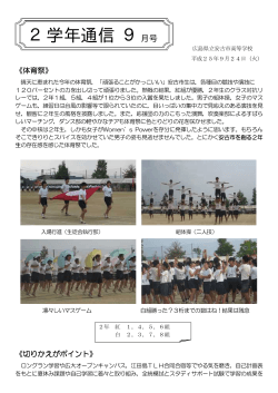
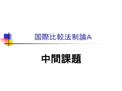
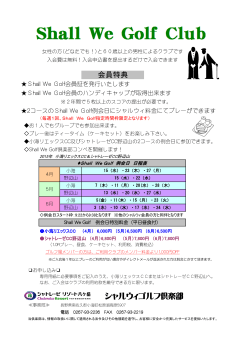
仕様書番号
Drawing No. JGM40-0149I
P. 1/15
納 入 仕 様 書
Specification of Piezoelectric Ceramic Filter
SFECP10M7FA00-R0
SFECP10M7FA00-B0
決定年月日
Date
承 認
Approved by
June 24, 2009
確 認
Checked by
担 当
Issued by
1. 適 用 Scope
当納入仕様書は、FM受信機のIF回路に使用するセラミックフィルタについて規定します。
この用途以外にご使用の場合には事前に当社へご連絡ください。
This product specification is applied to the ceramic filter intend to be used for FM receiver.
Please contact us before using any of the products in the applications not described above.
2. 品番 及び 貴社関連事項 Part Number
当 社 品 番
Murata Part Number
テーピング品
Taping
バラ品
Bulk
貴 社 部 品 番 号
Customer's Part Number
貴 社 仕 様 書 番 号
Customer's Drawing
Number
SFECP10M7FA00-R0
SFECP10M7FA00-B0
3. 定 格 Rating
項
3-1
3-2
3-3
3-4
目
規
Item
耐電圧 (各端子間)
Withstanding Voltage (Between each Terminals)
絶縁抵抗 (各端子間)
Insulation Resistance (Between each Terminals)
動作温度範囲
Operating Temperature Range
保存温度範囲
Storage Temperature Range
株式会社
村
田
製
作
所
格
Specification
D.C. 50V, 1 分 以下
D.C. 50V, 1 minute max.
100MΩ 以上 (D.C. 100V)
100MΩ min. (D.C. 100V)
-20 ∼ +80°C
-20 to +80°C
-40 ∼ +85°C
-40 to +85°C
Murata Manufacturing Co.,Ltd.
仕様書番号
Drawing No. JGM40-0149I
P. 2/15
4. 電気的性能 Electrical Characteristics
項
目
規
Item
4-1
中心周波数 (fo)
Center Frequency (fo)
4-2
3dB 帯域幅
3dB Bandwidth
20dB 帯域幅
20dB Bandwidth
挿入損失 (最小損失点にて)
Insertion Loss (at minimum loss point)
リップル (3dB 帯域内にて)
Ripple (within 3dB Bandwidth)
スプリアス減衰量
Spurious Response
4-3
4-4
4-5
4-6
格
Specification
ランク : 周波数
Rank : Frequency
A:10.700MHz±30kHz
280±50kHz
590kHz 以下 / max.
3.0±2.0dB
1.0dB 以下 / max.
35dB 以上 / min.
(9MHz ∼ fo 内にて)
(Range : 9MHz to fo)
35dB 以上 / min.
(fo ∼ 12MHz 内にて)
(Range : fo to 12MHz)
4-7
4-8
温度特性
-20°C ∼ +80°Cの範囲内での
中心周波数 (fo) 変化
Temperature Characteristics
Center Frequency (fo) Drift
within -20°C to +80°C
temperature range.
入出力整合インピーダンス (公称値)
Input/Output Impedance (Nominal)
20°C時基準にて
±50ppm./°C 以内
±50ppm./°C max.
from initial value at 20°C
330Ω
中心周波数 (fo) は3dB帯域の中心点を中心周波数とします。(4-1/4-7項)
Center Frequency (fo) : Defined as the center of 3dB Bandwidth. (4-1/4-7)
株式会社
村
田
製
作
所
Murata Manufacturing Co.,Ltd.
仕様書番号
Drawing No. JGM40-0149I
P. 3/15
5. 測定方法 Measuring Method
3/20dB 帯域幅
5-1-1
3/20dB Bandwidth
最小損失レベルより3dBもしくは20dB減衰する上下2点間の
幅とします。
Signifies a difference between the two frequencies where the
attenuation becomes 3dB or 20dB from the level of the
minimum loss point.
挿入損失
5-1-2
20・log(
Insertion Loss
E1
) (dB) (E1=S.S.G. 開放端出力電圧)
2・E2
(E1=S.S.G. Output Voltage)
リップル
5-1-3
通過帯域内において、出力レベルの山と隣り合う谷の差で
最大のものを電圧比で表します。
If there are peaks and valleys in a pass bandwidth, the ripple
expresses the maximum level difference of voltage ratio
between the peak level and valley level in the pass
bandwidth by using dB.
Ripple
スプリアス減衰量
5-1-4
Spurious Response
5-2
測定条件
規定の周波数範囲に於いて通過帯域外での最大出力点と通
過帯域内の最小損失点との電圧比で表します。
Expressed as the difference of voltage ratio between
minimum attenuation point in the stopband range and
minimum loss point in the pass bandwidth by using dB.
Measuring Condition
温 度 25±3°C、 湿 度 65±5%R.H. を 標 準 測 定 状 態 と し 、 特 に 疑 義 を 生 じ な い 場 合 は 、温度
20±15°C、湿度65±20%R.H.の範囲内で測定します。
Parts shall be measured under a condition (Temperature:20±15°C, Humidity:65±20%R.H.)
unless the standard condition (Temperature:25±3°C, Humidity:65±5%R.H.) is regulated to
measure.
5-3
測定回路
Measuring Circuit
(1) (2) (3)
R1
Rg
S.S.G.
E1
R2
C2
E2
RF Voltmeter
(1) 入 力
(2) アース
(3) 出 力
Input
Ground
Output
R1 + Rg = R2 = 330Ω±5%, Rg = 50Ω
C2 = 10pF (治具の浮遊容量及び RF Voltmeter の入力容量を含む)
(Including stray capacitance and Input capacitance of RF Voltmeter)
E1 : S.S.G. 開放端出力電圧 S.S.G. Output Voltage
株式会社
村
田
製
作
所
Murata Manufacturing Co.,Ltd.
仕様書番号
Drawing No. JGM40-0149I
P. 4/15
6. 外形寸法図 Dimensions
6.9±0.3
4.05±0.4
(3)
1.2±0.5
1.5±0.2
*
1.2±0.3
**
2.9±0.3
1.2±0.5
(2)
(1) 入 力
(2) アース
(3) 出 力
(1)
平面電極
Bottom Electrode
1.5±0.2
端面電極
Side Electrode
表示
Input
Ground
Output
Marking:
B
*
1.0±0.5
1.0±0.5
1.0±0.5
:製造年月度
EIAJ Monthly Code
**:中心周波数ランク表示
Center Frequency Rank Code
単位 Unit:mm
(推奨ランド寸法)
(Recommended Land Pattern)
1.2
1.2
材料表
外装基板
Substrate
外部端面電極
Edge Electrode
圧電素子
Element
4.0
1.2
1.65
1.65
2.85
2.85
株式会社
村
田
製
作
所
Materials
絶縁セラミクス
Ceramics
Ni + Cu + Ag
P.Z.T.
Murata Manufacturing Co.,Ltd.
仕様書番号
Drawing No. JGM40-0149I
P. 5/15
7. 機械的性能 Physical Characteristics
項 目
Item
7-1
試験後の規格
Specification
After Test
試 験 条 件
Test Condition
下図に示す様に加圧し、1回1秒の割合で5回加
圧する。プリント基板は第1図を使用します。
Bend Strength PCB Filter soldered on a PCB (see Fig. 1) is pressed
5 times (Duration : 1sec.).
基板たわみ強度
第1表を
満足します。
加圧治具
Pressing rod
20
加圧
load
10
PCB
ø5
支持台
Supporting rod
±1.0
45
試験部品
Sample under the test
中心位置ずれ
Off center
45
3
R10
The measured
value shall meet
Table 1.
基板厚み / PCB thickness : 0.8mm
単位 / unit : mm
7-2
はんだ付性
MIL-STD-202E-208Cに従い、230±5°Cの溶融は 端子表面の90%以
んだ中に3±0.5秒間浸す。
上 に は ん だ が 付着
します。
Terminals of filter shall be immersed in a The solder shall
soldering bath (230±5°C) for 3±0.5 seconds.
coat at least 90%
(refer to MIL-STD-202E-208C)
of the surface of
terminal.
振動数600 ∼ 3,300r.p.m.全振幅1.5mmの振動
をX.Y.Zの3方向に各1時間加えた後測定する。
Filter shall be measured after being applied 第1表を
vibration of 1.5mm with 600 to 3,300 r.p.m. band 満足します。
of vibration frequency to each of 3 perpendicular
directions for 1 hour.
1.0mの高さから、木板上に3回自然落下させた The measured
value shall meet
後測定する。
Filter shall be measured after 3 times random Table 1.
dropping from the height of 1.0m on the wooden
plate.
Solderability
7-3
耐振動性
Vibration
Resistance
7-4
耐落下衝撃
Random Drop
株式会社
村
田
製
作
所
Murata Manufacturing Co.,Ltd.
仕様書番号
Drawing No. JGM40-0149I
P. 6/15
8. 耐候性能 Environmental Characteristics
項 目
Item
8-1
温度60±2°C湿度90 +5 %R.H.の恒温恒湿槽中に
−0
て100時間保持した後、常温に取り出して1時間
後に測定する。
After being placed in a chamber (Humidity:90 to
95%R.H., Temperature:60±2°C)for 100 hours,
filter shall be measured after being placed in
natural condition for 1 hour.
耐湿特性
Damp Heat
(Storage)
はんだ耐熱性
Resistance to
Soldering Heat
(1)リフロー方式
Re-flow
Soldering
下記プロファイルのリフロー炉に1回通した
後、常温に取り出して4時間後に測定する。
Filter shall be measured after soldered once
within the following temperature condition and
then being placed in natural condition for 4 第1表を
満足します。
hours.
5 秒 / sec.
240
温 度 Temperature (°C)
8-2
試験後の規格
Specification
After Test
試 験 条 件
Test Condition
The measured
value shall meet
Table 1.
230
徐冷
Gradual
Cooling
150
60
時間 Time (sec.)
リード部をはんだこて温度280±5°Cで3.0±0.5秒
間当て、常温に4時間放置後に測定する。
Lead terminal is directly contacted with the tip of
soldering iron of 280±5°C for 3.0±0.5 seconds,
and then being placed in natural condition for 4
hours.
(2)コテ付方式
Soldering
with Iron
株式会社
30
村
田
製
作
所
Murata Manufacturing Co.,Ltd.
仕様書番号
Drawing No. JGM40-0149I
P. 7/15
項 目
Item
8-3
温度85±2°Cの恒温槽中に100時間保持し、常温
に取出して、1時間後に測定する。
After being placed in a chamber (Temperature:
85±2°C) for 100 hours, filter shall be measured
after being placed in natural condition for 1 hour.
温度-40±2°Cの恒温槽中に100時間保持し、常温
に取出して、1時間後に測定する。
After being placed in a chamber (Temperature:
-40±2°C) for 100 hours, filter shall be measured
after being placed in natural condition for 1 hour.
温 度 -55°C の 恒 温 槽 中 に 30 分 間 保 持 後 、 温 度
+85°Cの恒温槽中に直ちに移し、30分間保持す
る。これを1サイクルとし、全5サイクル行い、
常温に取り出して1時間後に測定する。
After temperature cycling of -55°C (30 minutes)
to +85°C (30 minutes) is performed 5 times, filter
shall be measured after being placed in natural
condition for 1 hour.
高温放置
Dry Heat
(Storage)
8-4
低温放置
Cold
(Storage)
8-5
熱衝撃特性
Thermal Shock
※
試験後の規格
Specification
After Test
試 験 条 件
Test Condition
第1表を
満足します。
The measured
value shall meet
Table 1.
注意 : 製品はいずれの試験前後においても、チップ単体として測定します。
Note : Filter shall be measured as a single unit (without any additional parts)
for each above mentioned tests.
第1表
※
※
※
※
※
項 目
Item
中心周波数の変化
Center Frequency Drift
3dB 帯域幅の変化
3dB Bandwidth Drift
20dB 帯域幅の変化
20dB Bandwidth Drift
挿入損失の変化
Insertion Loss Drift
試験後のスプリアス減衰量
Spurious Response
注意
Note
株式会社
Table 1
規 格
Specification After Test
±30kHz 以内 / max.
±20kHz 以内 / max.
±30kHz 以内 / max.
±2dB 以内 / max.
35dB 以上 / min.
: 各変化量は試験前の初期値を基準とします。
: The limits in the above table refer to
the initial measurements.
村
田
製
作
所
Murata Manufacturing Co.,Ltd.
仕様書番号
Drawing No. JGM40-0149I
P. 8/15
第1図 信頼性試験用プリント基板
Fig. 1 PCB for Physical and Environmental Test
7.4
0.0
A
ø6.5
50.0
0.0
25.0
100
ø4.5
20.0
25.0
1
1
0.0
1.0
2.0
4.0
6.0
36.0
37.0
38.0
39.0
40.0
A部詳細図
Wide view of A
5.5
1.4
4.0
3.8
1
1.4
単位 Unit:mm
*
部はソルダーレジスト塗布部を示します。
It shows solder resist land pattern.
プリント基板材質 :
PCB Material
:
株式会社
村
田
製
作
ガラスエポキシ (t=0.8mm)
Glass Epoxy (t=0.8mm)
所
Murata Manufacturing Co.,Ltd.
仕様書番号
Drawing No. JGM40-0149I
P. 9/15
9. プラスチックテープ収納方法 Taping Method of Plastic Package
プラスチックテープ外形寸法図
Dimensions of Carrier Tape
4.0±0.1
1.75±0.1
2.0±0.05
**
**
**
**
**
4.0±0.1
10°max.
3.3±0.1
チップフィルタ
Chip Filter
3°max.
12.0±0.2
*
1.9±0.1
*
7.3±0.1
*
+0.1
-0.05
*
1.7
カバーテープ
Cover Film
引きはがし強度
Peeling strength
(0.1 to 0.7N)
*
5.5±0.05
+0.1
ø1.5 -0.0
0.3±0.05
9-1
テープ引き出し方向
User direction of feed
単位 Unit:mm
・カバーテープ側に品番表示がきます。
Part Number marked side is always facing upside.
・キャビティテープの送り穴側に入力端子がきます。
The feeding holes side of cavity tape is always input terminal.
株式会社
村
田
製
作
所
Murata Manufacturing Co.,Ltd.
仕様書番号
Drawing No. JGM40-0149I
9-2
リール外形寸法図
P. 10/15
Dimension of Reel
2.0±0.5
(ø180)
ø13.0±0.5
19.5 max.
12.5
+1.0
-0
単位 Unit:mm
9-3
テーピング方法
Taping Method
9-3-1
テープは右巻き(テープの端を手前に取り出した時、送り穴が右側になる)とします。
The carrier tape shall be wound clockwise. The feeding holes shall be to the right side as the
tape is pulled toward the user.
9-3-2
カバーテープはキャビティテープの送り穴にかからないこと。又、キャビティテープからは
み出さないこと。
Cover film shall not cover the feeding holes of cavity tape, and not exceed cavity tape.
9-3-3
トレーラー部には40 ∼ 190mm、リーダテープ部には240 ∼ 280mmのチップの入ってい
ない部分を設けます。リーダ部のテープの長さはチップの入っていない部分を含み400 ∼
560mm 設けます。(第2図)
Empty tape area of 40 to 190mm shall exist at the end of the tape and 240 to 280mm at the
tip of the tape. Extended cover film shall exist of 400 to 560mm including leader cavity area.
(Fig. 2)
9-3-4
テープの巻き終わりは、接着テープ(30 ∼ 50mm)でカバーテープのリーダー部をリール
側面に貼りつけます。
The tip of the cover film shall be adhered to the side of reel with adhesive tape (30 to 50mm).
9-3-5
カバーテープの170°反転引きはがし強度は0.1 ∼ 0.7N(参考値)とします。
The cover film peel strength force shall be 0.1 to 0.7N (reference) which measured at 170
degrees with respect to the carrier tape.
株式会社
村
田
製
作
所
Murata Manufacturing Co.,Ltd.
仕様書番号
Drawing No. JGM40-0149I
P. 11/15
9-3-6
チップの向きは、裏表の反転のなきこととします。
The direction of filter shall be fixed.
9-3-7
チップは端数を除いて1リール2,000個収納とします。
A reel shall contain 2,000pcs of filter.
9-3-8
リール側面に表示ラベルを貼り、当社品番・貴社部品番号・数量及び、検査番号を記入しま
す。
Part Number, Customer's Part Number, quantity and Outgoing Inspection Number shall be
given to the each reel.
(ø180)
トレ−ラー部
Trailer Cavity
40 to 190
チップ実装部
Contain part
リーダーテープ部
Leader Cavity
240 to 280
400 to 560
単位 Unit:mm
第2図
Fig. 2
株式会社
村
田
製
作
所
Murata Manufacturing Co.,Ltd.
仕様書番号
Drawing No. JGM40-0149I
10.
!
注意
P. 12/15
Cautions
10-1 用途の限定 Limitation of Applications
当製品について、その故障や誤動作が人命または財産に危害を及ぼす恐れがある等の理由に
より、高信頼性が要求される以下の用途でのご使用をご検討の場合は、必ず事前に当社まで
ご連絡下さい。
①航空機器 ②宇宙機器 ③海底機器 ④原子力制御機器 ⑤医療機器
⑥輸送機器(自動車、列車、船舶等) ⑦交通用信号機器 ⑧防災/防犯機器
⑨情報処理機器 ⑩その他上記機器と同等の機器
Please contact us before using our products for the undermentioned applications requiring
especially high reliability in order to prevent defects which might directly cause damage to
other party’s life, body or property (listed below).
①Aircraft equipment
②Aerospace equipment
③Undersea equipment
④Power plant control equipment
⑤Medical equipment
⑥Transportation equipment(automobiles, trains, ships)
⑦Traffic signal equipment
⑧Disaster prevention / crime prevention equipment
⑨Data-processing equipment
⑩ Applications of similar complexity or with reliability requirements comparable to the
applications listed in the above
10-2 フェールセーフ機能の付加 Fail-safe
当製品に万が一異常や不具合が生じた場合でも、二次災害防止のために完成品に適切なフェ
ールセーフ機能を必ず付加して下さい。
Be sure to provide an appropriate fail-safe function on your product to prevent a second
damage that may be caused by the abnormal function or the failure of our product.
株式会社
村
田
製
作
所
Murata Manufacturing Co.,Ltd.
仕様書番号
Drawing No. JGM40-0149I
P. 13/15
11. 使用上の注意 Caution for Use
11-1
規格以上の衝撃が印加された場合、不具合が生じる事があります。取り扱いには充分ご注意
下さい。
The component will be damaged when an excessive stress is applied.
11-2
基板に実装された状態で過度の力が加わると不具合を生じる事が有りますので取り扱いには
充分ご注意下さい。
The component may be damaged if excess mechanical stress is applied to it mounted on the
printed circuit board.
11-3
基板設計の際には、基板のそり・たわみに対して極力ストレスが加わらない様な部品配置に
して下さい。
Design layout of components on the PC board to minimize the stress imposed on the warp or
flexure of the board.
[部品方向]
[Component direction]
ストレスの作用する方向に対して横向きに部品を配置して下さい。
Put the component lateral to the direction in which stress acts.
[基板ブレイク近辺でのチップ配置]
[Component layout close to board]
ミシン目
Perforation
A
B
A>C>Bの順でストレスを受けやすくなります。
Susceptibility to stress is in the order of : A>C>B
スリット
Slit
C
11-4
ランド寸法により、部品実装時の機械的強度が異なります。基板設計時にはランド寸法、形
状について配慮願います。
After installing chips, if solder is excessively applied to the circuit board, mechanical stress will
cause destruction resistance characteristics to lower. To prevent this, be extremely careful in
determining shape and dimension before designing the circuit board diagram.
株式会社
村
田
製
作
所
Murata Manufacturing Co.,Ltd.
仕様書番号
Drawing No. JGM40-0149I
P. 14/15
11-5
当製品を基板に実装する際、実装材の位置の爪や吸着ノズル材構部品が摩擦していると、チ
ップ部品に異常な衝撃が加わり、チップ部品を破壊する事があります。この種のトラブルを
事前に紛止するためにも、実装機に推奨されている定期メンテナンスを実施して下さい。
When the positioning claws and pick up nozzle are worn, the load is applied to the chip while
positioning is concentrated to one positioning accuracy, etc. Careful checking and
maintenance are necessary to prevent unexpected trouble.
11-6
はんだごてを使用してチップ修正をする場合、こてが直接製品にあたらないよう配慮して下
さい。又、はんだ付け時間が長くなるとはんだくわれが発生することがあります。はんだ付
けの際には、銀入りはんだの使用等の配慮を願います。
When correcting chips with a soldering iron, the tip of the soldering iron should not directly
touch the chip component. Depending on the soldering conditions, the effective area of
terminations may be reduced. the use of solder containing Ag should be done to prevent the
electrode erosion.
11-7
当製品は密閉構造ではありませんので洗浄しないで下さい。
Do not clean or wash the component as it is not hermetically sealed.
11-8
本体を外装樹脂等でコーティングする場合は、条件を充分ご確認の上ご使用下さい。
In case of covering filter with over coat, conditions such as material of resin, cure temperature,
and so on should be evaluated well.
11-9
リフローはんだ付けにおいて、酸性の強い(塩素含有量0.2wt%を越えるもの)フラックスの
使用は避けて下さい。
Do not use strong acidity flux, more than 0.2wt% chlorine content, in re-flow soldering.
11-10
製品の測定に際しては、正しくマッチングをとって下さい。浮遊容量の影響等により、マッ
チングが正しく取られていない場合、規格通りの性能が得られない事があります。
Accurate test circuit values are required to measure electrical characteristics.
It may be a cause of mis-correlation if there is any deviation, especially stray capacitance,
from the test circuit in the specification.
株式会社
村
田
製
作
所
Murata Manufacturing Co.,Ltd.
仕様書番号
Drawing No. JGM40-0149I
12.
!
お願い
P. 15/15
Note
12-1
ご使用に際しましては、貴社製品に実装された状態で必ず評価して下さい。
Please make sure that your product has been evaluated In view of your specifications with our
product being mounted to your product.
12-2
当製品を当納入仕様書の記載内容を逸脱して使用しないで下さい。
You are requested not to use our product deviating from the agreed specifications.
12-3
お手数ですが、当納入仕様書に貴社受領印を押印の上、1部を弊社へご返却下さい。
3ヶ月以内にご返却いただけない場合、又は、当納入仕様書をご返却いただく前にご注文を
いただいた場合は、当納入仕様書は、その時点で受領されたものとさせていただきます。
Please return one duplicate of this product specification to us with your signature to
acknowledge your receipt . In case of no return within three months from submission date, or if
we receive order before the duplicate is returned, this product specification will be deemed to
have been received by you.
12-4
弊社は、仕様書、図面その他の技術資料には、取引に関する契約事項を記載することは適切
ではないものと存じております。従って、もし、貴社が作成されたこれら技術資料に、品質
保証、PL、工業所有権等にかかる弊社の責任の範囲に関する記載がある場合は、当該記載
は無効とさせていただきます。これらの事項につきましては、別途取引基本契約書等におい
てお申し越しいただきたくお願いします。
We consider it not appropriate to include any terms and conditions with regard to the business
transaction in the product specifications, drawings or other technical documents. Therefore, if
your technical documents as above include such terms and conditions such as warranty
clause, product liability clause, or intellectual property infringement liability clause, they will be
deemed to be invalid.
株式会社
村
田
製
作
所
Murata Manufacturing Co.,Ltd.
© Copyright 2026 ExpyDoc