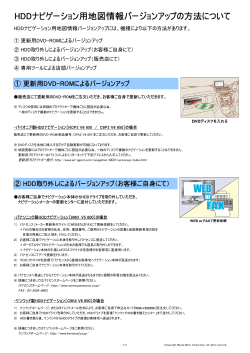
推奨ステッピングモータドライバ
Stepping Motor Driver recommendation
KSSでは、MoBoシリーズ及びミニチュアアクチュエータシリーズをより使いやすくするため、
推奨ドライバを付属品として用意しています。
KSS provides recommended Stepping Motor Driver for MoBo series and Miniature Actuator series
in order to make it easy to use.
●標準ドライバ/ Standard Stepping Motor Driver
KR-A5CC
DC24V 5相ステッピングモータ用ドライバです。フルステップ、ハーフステップの切り替えが可
能です。
自動カレントダウン機能も兼ね備えています。
This Driver is for 5-phase Stepping Motor operated by DC24V power supply. It has
automatic current reduction circuits. You can choose full-step or half step function.
DC24V入力 5相ステッピングモータドライバ
DC24V Input 5-phase Stepping Motor Driver
0.1∼0.9A / 相対応
0.1∼0.9A / phase
DC24V
項目 Items
駆動電流 Output current
(出荷時 0.35A/相)
(0.35A/phase at shipping)
定格電流0.1~0.9A/相 Rated current : 0.1~0.9A/phase
バイポーラペンタゴン定電流駆動方式 Bipolar pentagon constant current drive
駆動方式 Driving Type
信号名 Signal name
入力信号
回路
CW+
CWCCW+
CCWH.O.+
H.O.-
Functional description
入力抵抗 Input resistance
Pulse signal input for 1 clock mode
390Ω
CW rotation input for 2 clock mode
Rotational direction input for 1 clock
1クロック方式時の回転方向指示入力
390Ω
CCW rotation input for 2 clock
2クロック方式時の逆転信号入力
Motor exciting OFF control signal
モータ励磁OFF制御信号
390Ω
"H" for motor exciting OFF
“H”でモータ励磁OFF
Pulse width : 0.5μs min., Rising-up time : 1μs max.
パルス幅 0.5μsec以上、立上り立下り時間 1μsec以下
Pulse interval : 0.5μs min., Pulse frequency : 50kpps max.
パルス間隔 0.5μsec以上、パルス周波数 50kpps以下
Pulse voltage : "H" for 4~8V & “L” for 0~0.5V
パルス電圧“H”:4~8V “L”:0~0.5V
フォトカプラの電流がOFF(論理L)からON(論理H)で動作 Triggerd at the edge of OFF(Logic"L")to ON(Logic"H")of photo-coupler current
CCW rotation with CCW input of "L" in 1-clock system
1クロック方式時、CCW入力“L”の時CCW回転
機能説明
1クロック方式時のパルス信号入力
2クロック方式時の正転信号入力
駆動電流は、CP+ CP-に電圧計を接続しRUNボリュームを回して、次式で決まる電圧に設定する
To change the RUN current, connect the CP+ to the(+)terminal of the voltmeter and the CPto the(-)terminal of the voltmeter then adjust RUN CURRENT volume.
CP voltage(V)
CP電圧(V)
DIP SW
駆動電流(A)
= Setting current(A)=
types can be set with up to 250 divisions.
4
4
設定例)駆動電流を0.35A/相に設定する場合は、CP電圧を1.4Vに調整する
Setting example)When drive current is set to 0.35A/phase, the CP voltage is
adjusted to 1.4V.
駆動電流値設定
Setting of driving current
KR-A535M
AC100∼220Vで使用可能な5相ステッピングモータ用マイクロステップドライバです。
最大分割数は250分割が可能です。
Micro-Step Driver for 5-phase Stepping Motor, Which can be used with AC100∼220V
STOP
RUN CURRENT
RUN
CP- CP+
注)駆動電流の設定は、モータを駆動している状態で実施する
Note)Run current should be changed during the operating of motor.
モータが停止している時の電流値を設定。STOPボリュームにて設定
カレントダウン値は、駆動電流値に対する割合(%)にて設定
カレントダウン値設定
STOP CURRENT
In order to reduce the heat adjusting the current, change it using STOP CURRENT volume.
The setting value of STOP CURRENT volume is a percentage of the setting volume of RUN CURRENT.
設定例)駆動電流値を1.4Aで設定しSTOPボリュームを50%に設定した場合、停止時電流は0.7A/相になる。
Ex)After setting 1.4A for Run current then put STOP CURRENT volume at 50%, the stop current will be 0.7A.
Setting of Stop current
ディップスイッチ設定
(出荷時設定すべてOFF)
No.
表示 Symbol
1
1/2 CLK
Setting of Dip-switches
(All off at shipping)
機能 Function
クロック方式切替
Switching of clock
分割数設定
Full / Half
2
Setting of Interpolation
ON
1クロック方式
1 clock mode
フルステップ(0.72゜
)
Full-step(0.72゜
)
OFF
2クロック方式
2 clock mode
ハーフステップ(0.36゜
)
Half-step(0.36゜
)
25% 75%
OFF
↓
ON
12
動作周囲温度・湿度
0~40℃ 85%RH以下(但し、結露なきこと)
Operating temperature & humidity 0~40℃ 85%RH max. without any dew condensation.
保存周囲温度・湿度
-10~70℃ 85%RH以下(但し、結露なきこと)
Storage temperature & humidity
-10~70℃ 85%RH max. without any dew condensation.
約130g
質量
Approximately 130g
Mass
Stepping Motor Driver
ステッピングモータードライーバ
●ドライバ外形寸法 / Driver Outer Dimensions
4.5
45
22.5
SD4030B2
2相転造MoBo
(バイポーラ)及びミネベアモータ製(2相 □25)ステップモータ付ミニチュアアク
チュエータ用の推奨ドライバです。8種類のステップ角設定が可能です。
(Bi-polar)
This is recommended 2-phase stepping Motor Driver for 2-phase Rolled MoBo
and Miniature Actuator series with □25 size 2-phase Stepping Motor made by Minebea
Motor. It has Micro-Step function with 8-step angle.
87
93
各推奨ドライバの仕様と外形図を次ページ以降に記載します。
Outer dimensions and specifications of KSS recommended Driver are shown from next page.
55.5
DC20-35V
20
RUN CURRENT
0.5A
1.5A
75%
25%
+
-
V101
CHECK POINT
32
-
+
+5V(OUT)
Max 30mA
BLACK
GREEN
ORANGE
RED
HOLD OFF
-
+
MOTOR
BLUE
CW
CCW
-
+
-
+
KR-A5CC
POWER
1/2 CLK
FULL HALF
87
STOP CURRENT
Stepping Motor Driver
ステッピングモータードライーバ
Full-step or Half-step by Dip switch.
Case type
仕様値 Specification
DC20-35V(-10%,+20%)max.3A
電源 Power supply
KR-A55MC
DC24V 5相ステッピングモータ用ドライバです。
16種類のステップ角が設定でき、最大分割数は
250分割が可能なマイクロステップドライバです。
Micro-Step Driver for 5-phase Stepping Motor with DC24V power supply. 16 step angle
KS9110
多摩川精機製
(2相 □28)ステップモータ付ミニチュアアクチュエータシリーズに推奨の2相ス
テッピングモータ用ドライバです。ディップスイッチにより、フルステップ、ハーフステップの切
り替えができます。
This is recommended 2-phase stepping Motor Driver for Miniature Actuator series with
□28 size 2-phase Stepping Motor made by TAMAGAWA SEIKI. It can be selected for
ケースタイプ
Full / Half-Step
■仕 様 Specifications
Input signal
circuit
power supply. 16 step angle types can be set with up to 250 divisions.
フル・ハーフステップ
ON
ステッピングモータドライバ編 Stepping Motor Driver
KR-A5CC
V102
項目 Items
Micro-step
ケースタイプ
Case type
1
Setting of dip-switches
(All off at shipping)
動作周囲温度・湿度
項目 Items
仕様値 Specification
電源 Power supply
駆動電流 Output current
(出荷時 0.75A/相)
(0.75A/phase at shipping)
駆動方式 Driving Type
DC20-35V(-10%,+20%)max.3A
定格電流0.4~1.4A/相 Rated current : 0.4~1.4A/phase
デジタルSW [RUN]によって、0.4~1.4A/相まで設定が可能。
Capable of setting the current to 0.4~1.4A/phase by the digital switch "RUN"
バイポーラペンタゴン定電流駆動方式 Bipolar pentagon constant current drive
信号名 Signal name 機能説明
CW+
1クロック方式時のパルス信号入力
2クロック方式時の正転信号入力
CW-
入力抵抗 Input resistance
Functional description
Pulse signal input for 1 clock mode
270Ω
CW rotation input for 2 clock mode
Rotational direction input for 1 clock
CCW+
1クロック方式時の回転方向指示入力
270Ω
CCW rotation input for 2 clock
2クロック方式時の逆転信号入力
CCW入力信号
Motor excitation OFF control signal
H.O.+
モータ励磁OFF制御信号
390Ω
回路
"H" for motor exciting OFF
“H”でモータ励磁OFF
H.O.Input signal
D.S.+
Micro-step interpolation selection
マイクロステップ分割選択信号
390Ω
circuit
"L" for MS1 & "H" for MS2
D.S.“L”でMS1、“H”でMS2を選択
Pulse width : 0.25μs min., Rising-up time : 1μs max.
パルス幅 0.25μsec以上、立上り立下り時間 1μsec以下
パルス間隔 0.25μsec以上、パルス周波数 500kpps以下 Pulse interval : 0.25μs min., Pulse frequency : 500kpps max.
Pulse voltage : "H" for 4~8V & “L” for 0~0.5V
パルス電圧“H”:4~8V “L”:0~0.5V
フォトカプラの電流がOFF(論理L)からON(論理H)で動作 Triggerd at the edge of OFF(Logic"L")to ON(Logic"H")of photo-coupler current
CCW rotation with CCW input of "L" in 1-clock system
1クロック方式時、CCW入力“L”の時CCW回転
信号名 Signal name 機能説明
出力容量 Output capacity
Functional description
Origin exciting output signal
Z.P.+
DC30V max.
原点励磁信号出力
出力信号
Switched ON while origin is being excited
原点励磁時ON
50mA max.
Z.P.回路
励磁シーケンスが[0]の時ONになり、0.72°
のモータの場合は7.2度毎に出力される。電源投入時にステップ角
Output signal
を切替えた時は出力されない場合がある。
Circuit
This signal is ON at the exciting sequence of [0] and is transmitted at each 7.2 degrees for the Step Motor
with 0.72°
steps. When micro-step angle is changed after the power supply is turned on, it may not be transmitted.
マイクロステップ分割設定
(出荷時MS1:5、MS2:0)
Setting of micro-step
Interpolation
(MS1:5, MS2:0 at shipping)
Setting of driving current
(Setting "5" at shipping)
自動カレントダウン設定
(出荷時設定:5)
Automatic current-down
(Setting "5" at shipping)
V103
OFF
自己テスト機能
TEST
約250ppsで回転
通常動作
Self test function
2
1 / 2 CLK
3
C/D
Rotating at 250pps
1クロック方式
1 clock mode
クロック方式切替
Switching of clock
自動カレントダウン
しない
Automatic current-down
Normal operation
2クロック方式
2 clock mode
する
Invaild
Vaild
ON
ON ← OFF
注2
(Note2)
保存周囲温度・湿度
-10 ∼ 70℃ 85%RH以下(但し、結露なきこと)
-10 ∼ 70℃ 85%RH Max. without any dew condensation.
Storage temperature
& humidity
質量
約220g
Approximately 220g
Mass
注1)
1パルスのマイクロステップ角度=基本ステップ角 / 分割数
注2)
分割数の設定に関らず内部で約250ppsを発生し、
ディップスイッチNo.2がONの時は、CCW回転、
OFFの時はCW回転。
Note 1)Micro-step angle for 1 pulse=Basic step angle / Number of interpolation
Note 2)Approx. 250pps is generated inside, regardless of splits setting ; CCW rotation when the dip switch NO.2 is ON, and CW rotation when the dip
switch NO.2 is OFF.
●ドライバ外形寸法 / Driver Outer Dimensions
4.5
4.5
38
20
38
39.5
74
75.7
Stepping Motor Driver
ステッピングモータードライーバ
Stepping Motor Driver
ステッピングモータードライーバ
駆動電流の設定
(出荷時設定:5)
1種類のみのマイクロステップ駆動の場合はデジタルSW MS1で分割数を設定する。
2種類のマイクロステップ駆動をさせる場合(往復運動時の行きと戻りでスピードを変える場合)は、デジタルSW
MS1、MS2で各々の分割数を設定する。
For micro-step driving of one type only, set the number interpolution using the digital SW MS1.
For micro-step driving of two types.(i.e. when changing speed for going and returning in reciprocating motion)
set respective numbers of interpolation using the digital SW MS1 and MS2.
5
6
7
8
9
0
1
2
3
4
設定番号 Set No.
分割数 Interpolation
4
5
8
10 16 20 25 40
1
2
注1)
A
B
C
D
E
F
Note 1)
50 80 100 125 200 250
MS1
MS2
マイクロステップ分割の設定番号0.1選択時は、内部にて4分割の低振動駆動となる。
When the setting of micro-step interpolating No. is "0.1", 1/4-interpolate low-frequency driving takes place inside.
モータ回転時の電流はデジタルSW RUN によって下表から選択して設定する。
The output current to the motor in rotation is set by the digital switch "RUN" to select from the table below.
4
0
1
2
3
5
6
7
8
9
設定番号 Set No.
0.4 0.5 0.57 0.63 0.71 0.77 0.84 0.9 0.96 1.02
電流(A)Current(A)
A
B
C
D
E
F
RUN
1.09 1.15 1.22 1.27 1.33 1.4
モータ停止時の電流はデジタルSW STOP によって下表から選択して設定する。
この数値はRUN電流に対するパーセントです。最終パルス入力後約500msで電流が減少する。
The output current to the motor at stationary is set by the digital switch "STOP" to select from the table below.
The value is set by the percent to "RUN" current. The current decreases at approx. 500ms after the last pulse.
0
1
2
3
4
5
6
7
8
9
設定番号 Set No.
27 31 36 40 45 50 54 58 62 66
パーセント
(%)
STOP
A
B
C
D
E
F
70 74 78 82 86 90
ON
0 ∼ 40℃ 85%RH以下(但し、結露なきこと)
0 ∼ 40℃ 85%RH Max. without any condensation.
Operating temperature
& humidity
100
■仕 様 Specifications
機能
Function
105
マイクロステップ
ディップスイッチ設定
(出荷時設定すべてOFF)
表示
symbol
94
0.4∼1.4A / 相対応
0.4∼1.4A / phase
DC24V
No.
123
DC24V入力 マイクロステップドライバ
DC24V Input Microstep Driver
仕様値 Specification
100
KR-A55MC
V104
AC100-220V入力 マイクロステップドライバ
AC100-220V Input Microstep Driver
1
TEST
(All off at shipping)
2
1 / 2 CLK
3
C/D
Setting of dip-switches
フルコネクタタイプ
Micro-step
ディップスイッチ設定
(出荷時設定すべてOFF)
Full connector
動作周囲温度・湿度
保存周囲温度・湿度
駆動方式 Driving Type
信号名 Signal name
CW+
CWCCW+
CCWH.O.+
H.O.D.S.+
D.S.-
入力信号
回路
Input signal
circuit
出力信号
回路
定格電流0.4~1.4A/相 Rated current : 0.4~1.4A/phase
デジタルSW [RUN]によって、0.4~1.4A/相まで設定が可能。
Capable of setting the current to 0.4~1.4A/phase by the digital switch "RUN"
Normal operation
2クロック方式
2 clock mode
クロック方式切替
Switching of clock
自動カレントダウン
Automatic current-down
通常動作
しない
OFF → ON
注2(note2)
する
Invaild
Vaild
Approximately 660g
注1)
1パルスのマイクロステップ角度=基本ステップ角 / 分割数
注2)
分割数の設定に関らず内部で約250ppsを発生し、
ディップスイッチNo.2がONの時は、
CCW回転、OFFの時はCW回転。
Note 1)Micro-step angle for 1 pulse=Basic step angle / Number of interpolation
Note 2)Approx. 250pps is generated inside, regardless of splits setting ; CCW rotation when the dip switch NO.2 is ON, and CW rotation when the dip
バイポーラペンタゴン定電流駆動方式 Bipolar pentagon constant current drive
機能説明
1クロック方式時のパルス信号入力
2クロック方式時の正転信号入力
1クロック方式時の回転方向指示入力
2クロック方式時の逆転信号入力
モータ励磁OFF制御信号
“H”でモータ励磁OFF
マイクロステップ分割選択信号
“L”でMS1、“H”でMS2を選択
Functional description
入力抵抗 Input resistance
Pulse signal input for 1 clock mode
270Ω
CW rotation input for 2 clock mode
Rotational direction input for 1 clock
270Ω
CCW rotation input for 2 clock
Motor exciting OFF control signal
390Ω
"H" for motor exciting OFF
Micro-step interpolation selection
390Ω
"L" for MS1 & "H" for MS2
Pulse width : 0.25μs min., Rising-up time : 1μs max.
パルス幅 0.25μsec以上、立上り立下り時間 1μsec以下
Pulse interval : 0.25μs min., Pulse frequency : 500kpps max.
パルス間隔 0.25μsec以上、パルス周波数 500kpps以下
Pulse voltage : "H" for 4~8V & “L” for 0~0.5V
パルス電圧“H”:4~8V “L”:0~0.5V
Triggerd at the edge of OFF(Logic"L")to ON(Logic"H")of photo-coupler current
フォトカプラの電流がOFF(論理L)からON(論理H)で動作
CCW rotation with CCW input of "L" in 1-clock system
1クロック方式時、CCW入力“L”の時CCW回転
信号名 Signal name 機能説明
原点励磁信号出力
Z.P.+
原点励磁時ON
Z.P.-
Output signal
Circuit
約250ppsで回転
Rotating at 250pps
1クロック方式
1 clock mode
約660g
Mass
Functional description 出力容量 Output capacity
Origin exciting output signal
DC30V max.
Switched ON while origin is being excited 50mA max.
励磁シーケンスが[0]の時ONになり、0.72°
のモータの場合は7.2度毎に出力される。電源投入時にステップ角
switch NO.2 is OFF.
●ドライバ外形寸法 / Driver Outer Dimensions
7
7108
4-M4 TAP
170
駆動電流 Output current
(出荷時 0.75A/相)
(0.75A/phase at shipping)
質量
170
AC100-220V(±10%)max.3A 50/60Hz
120
仕様値 Specification
電源 Power supply
自己テスト機能
Self test function
-10 ∼ 70℃ 85%RH以下(但し、結露なきこと)
-10 ∼ 70℃ 85%RH Max. without any dew condensation.
Storage temperature
& humidity
項目 Items
OFF
0 ∼ 40℃ 85%RH以下(但し、結露なきこと)
0 ∼ 40℃ 85%RH Max. without any condensation.
Operating temperature
& humidity
■仕 様 Specifications
ON
Function
108
20
20
4-M4 TAP
156
マイクロステップ
機能
symbol
156
AC100-220V
表示
No.
120
0.4∼1.4A / 相対応
0.4∼1.4A / phase
仕様値 Specification
123
項目 Items
ON
KR-A535M
を切替えた時は出力されない場合がある。
This signal is ON at the exciting sequence of [0] and is transmitted at each 7.2 degrees for the Step Motor
with 0.72°steps. When micro-step angle is changed after the power supply is turned on,it may not be transmitted.
1種類のみのマイクロステップ駆動の場合はデジタルSW MS1で分割数を設定する。
2種類のマイクロステップ駆動をさせる場合(往復運動時の行きと戻りでスピードを変える場合)は、デジタルSW
MS1、MS2で各々の分割数を設定する。
For micro-step driving of one type only, set the number interpolution using the digital SW MS1.
Setting of micro-step
For micro-step driving of two types.(i.e. when changing speed for going and returning in reciprocating motion)
interpolation
(MS1:5, MS2:0 at shipping) set respective numbers of interpolation using the digital SW MS1 and MS2.
マイクロステップ分割設定
(出荷時MS1:5、MS2:0)
5
5
122
122
124.8
124.8
5
5
40
40
42
42
駆動電流の設定
(出荷時設定:5)
Setting of driving current
(Setting "5" at shipping)
自動カレントダウン設定
(出荷時設定:5)
Automatic current-down
(Setting "5" at shipping)
モータ回転時の電流はデジタルSW RUN によって下表から選択して設定する。
The output current to the motor in rotation is set by the digital switch "RUN" to select from the table below.
設定番号 Set No.
0
1
2
3
4
5
6
7
8
9
電流(A)Current(A)
0.4 0.5 0.57 0.63 0.71 0.77 0.84 0.9 0.96 1.02
A
B
C
D
E
F
RUN
1.09 1.15 1.22 1.27 1.33 1.4
モータ停止時の電流はデジタルSW STOP によって下表から選択して設定する。
この数値はRUN電流に対するパーセントです。最終パルス入力後約500msで電流が減少する。
The output current to the motor at stationary is set by the digital switch "STOP" to select from the table below.
The value is set by the percent to "RUN" current. The current decreases at approx. 500ms after the last pulse.
設定番号 Set No.
0
パーセント
(%)
27
A
70
V105
Stepping Motor Driver
ステッピングモータードライーバ
Stepping Motor Driver
ステッピングモータードライーバ
設定番号 Set No.
0
1
2
3
4
5
6
7
8
9
分割数 Interpolation
1
2
4
5
8
10 16 20 25 40
A
B
C
D
E
F
50 80 100 125 200 250
MS1
MS2
注)マイクロステップ分割の設定番号0.1選択時は、内部にて4分割の低振動駆動となる。
Note)When the setting of micro-step interpolating No. is "0.1", 1/4-interpolate low-frequency driving takes place inside.
1
31
B
74
2
36
C
78
3
40
D
82
4
45
E
86
5
50
F
90
6
54
7
58
8
62
9
66
STOP
V106
KS9110
SD4030B2
DC24V入力 2相ステッピングモータドライバ
DC24V Input 2-phase Stepping Motor Driver
DC24V
0.35∼2A / 相
0.35∼2A / phase
フル・ハーフステップ
DC24V入力 2相マイクロステップドライバ
DC24V Input 2-phase Microstep Driver
基板タイプ
Full / half step
DC24V
Board type
■仕 様 Specifications
0.5∼3 / 相
0.5∼3A / phase
マイクロステップ
基板タイプ
Micro-step
Board type
■仕 様 Specifications
項 目 Items
仕様値 Specification
項 目 Items
内容 Description
備考 Note
電 源 Power supply
DC+24V ±10% 3A Max.(全消費電流)
(tatal current consumed)
0.35∼2A Max / 相 可変抵抗VRにて設定(出荷時 1A / 相)
0.35∼2A Max. / phase Variable resistor(VR)setting(Set to 1 A / phase when shipped)
入力電源電圧 Input voltagee
DC+18V∼40V
0.5∼3Apeak(±5%)/相
0.5∼3Apeak(±5%)/phase
電源24V を超える場合は減定格となります
バイポーラ定電流チョッパー方式
ユニポーラタイプでも使用可
自動カレントダウン
パルス停止後約0.7秒で電流をCDN ボリュームで
設定された電流に下げる
スイッチにより機能選択可能
Excitation method
(2 phase excitation at shipment)
フル / ハーフ
Full / half
入力信号回路
Input signal circuit
1パルス入力
1-pulse input
PULSE
DIR
イネーブル
ENABLE
(出荷時1パルス入力)
(Set to 1 pulse input at shipment)
出力信号
Output signal
CKOUT(CKO)
電源設定端子
(IS)
Current
terminal(IS)
Dip switch
(Set ON at shipment)
Dip switch
附属品
Accessories
質量
Mass
ON
2 phase excitation
OFF
ディップスイッチ
カレントダウン機能
Current down function
作動時
入力パルスの立ち上がりから約1sec後、
非作動時
出力電流が約50%にダウンします。
1
最大入力パルス周波数
Maximum input pulse cycle
RUN
調整機能
Adjusting
ディプスイッチ
ON
Approximately 1 sec after turning on
input pulse, output current drops
approximately 50%.
OFF
When not in operation
ON
ディップスイッチ
OFF
Dip switch
選択機能
Select function
入力信号
Input signals
Output signals
保存温度・湿度
コネクタハウジングXHP-6
(JST)1個、XHP-8
(JST)1個、コンタクトBXH-001T-P0.6
(JST)14個
Connector housing 1pc XHP-6(JST), 1pc XHP-8(JST), 14pcs contacts BXH-001T-P0.6(JST)
質量
出荷時は2A に設定される
For excitation current
The default factory setting is 2A.
RUN 電流の10%∼60%
For current down value on current down mode.
Selectable between 10% to 60% of RUN current.
ミックスディケイの比率設定用
(0%、20%、
40%、60%、80%) 出荷時設定80%
Mixed Decay ratio(0%、20%、40%、60%、80%)
The default factory setting is 80%
JOG の速度設定用
300pps∼14Kpps
For JOG speed setting.
カレントダウン時の電流設定用
分割数選択
1/2, 1/8, 1/10, 1/16, 1/20, 1/32, 1/40, 1/64
Select of Resolutions
自動カレントダウン有効/無効選択
スイッチON で有効、OFFで無効 出荷時設定 有効
指令パルス Pulse Command
指令パルスは1パルスと2パルスが選択できます。
D+,D-
指令方向 Direction Command
Selection of 1 pulse an 2 pulse for pulse command.
入力はフォトカプラで絶縁
OFF+,OFF-
励磁OFF No excitation
ALM+,ALM-
アラーム
(パワー素子過熱検出)
パワー素子内の温度が170℃(Typ.)
に達したときに出力
Alarm(Prospecting of over-heat for Power device)
Output at over 170℃(Typ.)of power device
Storage Temperature and Humidity
106g
励磁電流設定用
(0.5∼3A)
P+,P-
Operating Temperature and Humidity
Mass
100Kpps
Switch ON is active and OFF is no active. The default factory setting is ON.
SW-5 ONでJOG有効。SW-6 ON:CW, OFF:CCW
SW-5 ON is active for JOG, SW6 ON is CW, OFF is CCW
動作温度・湿度
-10∼70℃ 90%RH以下(結露なきこと) -10∼70℃ under 90% RH(no condensation)
Selectable by switch.
ON/OFF for function of auto current down mode.
JOG選択機能
Select of JOG function
外形寸法 Dimension
保存時 /Stand-by
Isolated by photo coupler
フォトカプラで絶縁、
正常時ON、
アラーム時OFF
Photo Isolation, ON is active, OFF is no active(ALARM).
W90×D55.5×H28
0∼40℃、35∼80% RH
結露なきこと No condensation
-20∼+85℃、35∼80% RH
結露なきこと No condensation
約106g
Approximately106g
(6.5)
●ドライバ外形寸法 / Driver Outer Dimensions
90
4
B6B-XH-A(JST)
相手XHP-6
(JST)
付属
Mating connector
XHP-6(JST)attached
54±0.2
82
4
2
6
1
5
JP1
8
1
6
6-φ8.5
CN2
CN1
55.5
JOG
JOG
1
65±0.2
4
(3.5)
6
44.5
RUN
64
SW-4
SW-5,6
0∼40℃ 90%RH以下(結露なきこと) 0∼40℃ under 90% RH(no condensation)
B8B-XH-A(JST)
(JST)
付属
相手XHP-8
Mating connector
XHP-8(JST)attached
MIX
SW-1,2,3
動作時 / During operation
●ドライバ外形寸法 / Driver Outer Dimensions
STOP
JOG
出力信号
1
Auto Current down
Adjusting to set lower current of CND volume after 0.7
second after pulse stop
It can be used for uni-polar type.
Stepping Motor Driver
ステッピングモータードライーバ
3
65±0.2
2-φ4
82
V107
3
28
(3)
17.5±0.2
10
2-φ4
32
Stepping Motor Driver
ステッピングモータードライーバ
Surrounding
environment
OFF
ディップスイッチ
(フルステップ/full step)
(V)=1
(A / 相)
出力電流確認用端子:0.23
Terminal for checking output current:0.23(V)=1(A/phase)
When in operation
周囲温湿度
ON
2 3
Dip switch
Dip switch
フォトカプラTLP521
(東芝) 入力抵抗220Ω
Photo coupler TLP521(Toshiba), Input resistance 200Ω
フォトカプラの入力電流10mA以上20mA以下
Photo coupler input current, over 10mA, below 20mA
DIR信号のフォトカプラの電流と回転方向
DIR signal's photo coupler current and rotation direction
2
ジャンパスイッチ
Jumper switch
ON
CW回転 rotation
1
OFF
CCW回転 rotation
注:CW入力時はCCW入力のフォトカプラ電流はOFF、
CCW入力時はCW入力のフォ
同時に、
CW、CCW入力にパルスを入力しないこと。
トカプラ電流はOFFのこと。
2
ジャンパスイッチ
Note : Make sure that CCW input photo coupler current is OFF during CW
Jumper switch
1
input and CW input photo coupler current is OFF during CCW input.
Never input pulse to both CW and CCW at the same time.
フォトカプラの電流がONでモータが無励磁、フォトカプラの電流がOFFでモータが励磁
When photo coupler current is ON, motor is not excitable.
When photo coupler current is OFF, motor is excitable.
パルス幅5μsec 以上、立上がり立ち下がり時間2μsec以下、フォトカプラの電流がONからOFFで動作
Pulse duration is 5μsec or more, rise / fall time is 2μsec or less.
Operation starts when photo coupler current is switched from ON to OFF.
入力パルス確認用ランド:TTL出力
Land for checking input pulse:TTL output
自動カレントダウン
(出荷時動作設定)
Automatic current down
OFF
2 相励磁
2 3
Chopper mode by Bipolar constant current
1
Input signal
ディップスイッチ
駆動方式 Drive method
7
入力信号
2パルス入力
2-pulse input
CW
CCW
Chopper mode by Uni-polar constant current
1-2 相励磁
2 3
1 相励磁
(ハーフステップ/half step)
1-phase excitation
ON
1-2 phase excitation
Being lower rated output current beyond Power Supply 24V
STOP
励磁方式
(出荷時2相励磁)
ユニポーラ定電流チョッパー方式
MIX
駆動方式 Drive method
出力電流 Output current
ON
出力電源 Output current
72
V108
© Copyright 2026 ExpyDoc