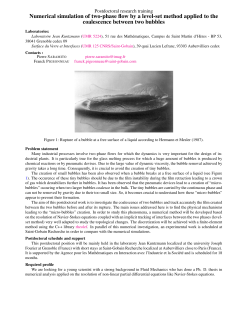
DAGA 2014 Oldenburg
Bubbles as hydrophones
Robert Mettin, Till Nowak, Andrea Thiemann, Carlos Cairós Barreto, Julian Eisener
Christian Doppler Laboratory for Cavitation and Micro-Erosion
Drittes Physikalisches Institut, Georg-August-Universität Göttingen
Friedrich-Hund-Platz 1, 37077 Göttingen, Germany
Email: [email protected]
augmented by a coupled translation equation [3] are
probably the best compromise between complexity and
accuracy. Any extended model including non-spherical
components will suffer from both additional need for
extracted observational data and blow-up of fitting
parameters. The latter appears as well as a problem if a nontrivial sound field is included, i.e., anything else but a
sinusoidal fundamental frequency driving pressure. Still, the
method might be suited for a limited amount of harmonics,
in particular if positional or translational data is recorded [4].
The fitting (iii) might use a full radius-time curve plus
position over time (if available), or just main observables
like maximum and minimum bubble sizes and their
respective phases, numbers and height of afterbounce
oscillations, etc. Of course, the existence of a perfect fit
cannot be expected as the model is idealistic, and system and
data are noisy. Therefore finding a suitable measure of the fit
quality and the tolerance margins might be problematic.
Furthermore, due to the nonlinearity of the underlying
equations, the radial motion is not harmonic (otherwise a
simple determination of maximum and minimum radius
would be sufficient), and uniqueness of the solution is not
ensured. Thus difficulties might arise from non-smooth
“fitness landscapes” in parameter space, for instance because
of hysteresis and multiple solutions. For the examples
shown, a fit “by hand” was done using parameter plane
diagrams of maximum radius as well as stability regions of
the spherical bubble shape [5]. For future automatic fit
procedures, the mentioned issues have to be addressed, and
additionally a good initial parameter guess might be
necessary.
Introduction
Direct acoustic pressure measurements in cavitating liquids
are often difficult: pressure sensors in form of standard
hydrophones are typically invasive and might disturb the
cavitation bubble field significantly (e.g. by attracting and
attaching bubbles), and the cavitation can have erosive and
destructing effects on the sensors. Furthermore, the presence
of bubbles is an inherent inhomogeneity which leads to high
fluctuations of the sound field in space and time. To cope
with this, spatial and temporal averaging is often employed
to obtain useful pressure data. However, sometimes less or
non-invasive pressure sensors of high spatial and temporal
resolution are demanded, for example to determine the true
local acoustic pressure amplitude acting on individual
bubbles in a bubble cloud or cluster. Sensors of choice are
fine needle hydrophones or fiber optic probes which,
however, have the drawbacks of high risk of damage and, for
the optic probes, low recording sensitivity. For some types
of problems, a way out could be the direct fitting of acoustic
pressure to high-speed observations of individual bubble
oscillations. Attractive sides of this idea to use the cavitation
bubbles themselves as hydrophones are the non-invasiveness
and the high resolution, and this method has already been
applied successfully for laser-induced bubbles [1] and in
single-bubble traps [2]. The suitability in multi-bubble
environments has not yet been demonstrated. Here we sketch
some background of the method and show two examples.
Method
The idea consists of a numerical fit of recorded oscillation
and potentially also translational bubble dynamics.
Necessary (and sometimes sufficient) fit parameters are
equilibrium bubble radius R0 and local (fundamental) driving
pressure amplitude pa. For taking into account the
translational motion, some assumption or information on the
local acoustic pressure gradient is needed as well. The
success of the method relies mainly on (i) accurate
observational data, (ii) a sufficiently complete fitting model,
and (iii) a converging fitting procedure. To ensure (i), a
transparent liquid is mandatory as well as a recording frame
rate reaching or superseding the acoustic frequency. A
certain amount of undersampling can be tolerable
(employing back projection onto a single period) if the
bubble oscillation / translation is stationary for some driving
periods, but in many cases the stationarity is limited by
collision with neighbor bubbles. In any case, the faster the
recording, the more accurate and reliable are the results. As a
model (ii), spherical bubble ODEs of Rayleigh-Plesset type
Examples
We employ the method to bubble oscillations below a
sonotrode horn tip working in the 20 kHz frequency range.
In such a set-up, bubble clouds directly in front of the tip can
dampen the sound field by absorption and scattering, and
estimated pressure values obtained from the analytic formula
for the symmetry axis of a circular piston source can be
much too high [6,7].
Figure 1: Pseudo-streak image of bubbles in water below a
sonotrode tip driven at 20 kHz (subsequent vertical frames
recorded at 250 kfps corresponding to 12.5 frames per
driving period; exposure time 1 Ps, image height 0.5 mm.)
Note the lower bubble which is oscillating strongly in
volume and jumping upwards during the collapse phase.
704
DAGA 2014 Oldenburg
The first data are recorded in water with a frame rate of 12.5
images per acoustic period, and they show a bubble
oscillating and translating upwards to the horn tip, see [8]
and Fig. 1. From this image series a radius-time curve and a
position-time trace are generated shown in Fig. 2(top).
Fitting by a Keller-Miksis model and an analytic piston
source field (on the symmetry axis) results in reasonable
agreement of both oscillation and translation for R0=15μm
and pa=150kPa, see Fig. 2(bottom). This means an effective
sound pressure of only about half the value derived
analytically from the actually observed sonotrode tip
velocity, the reduction being caused apparently by
absorption and scattering by other cavitation bubbles.
analysis of the bubble interior and its shape in the collapse
phase, e.g. by non-spherical numerical models employing
BEM or VoF methods. Note the second co-existing solution
(dashed lines in Fig. 4) which appears for different initial
conditions.
Figure 4: Comparison of experimentally measured values
(crosses) and best numerical fit (lines) for radius R vs. time
(top) and position z vs. time (bottom) for the case of Fig. 3.
The dashed lines correspond to a second solution of the
fitting Keller-Miksis equation for identical parameters.
Conclusion
Figure 2: Observed (top) and fitted (bottom) dynamics of
the lower bubble in Fig. 1, including radius R (green) and
position z (red) vs. time (acoustic cycles).
While numerical fitting of single bubble dynamics in multibubble environments might have some pit-falls, it proves to
be a reasonable method for acoustic pressure measurements
in special cases. For instance, the method has been shown
above to work for bubbles in sulfuric acid where no direct
hydrophone measurements were possible because of the
aggressive liquid. Future applications might give additional
quantitative information on effective sound fields in bubble
clouds and structures occurring in acoustic cavitation. Such
data is needed, for instance, for validation of sound wave
propagation models in bubbly liquids and for realistic
modeling of the attenuation due to the bubbles.
Figure 3: Part of the image series of a bubble below a
sonotrode tip in sulfuric acid, driven at 23 kHz (recorded
with 775 kfps; exposure time 1.3 Ps, image width 0.42mm).
The bubble is moving downwards (away from the tip).
Acknowledgement: The authors thank W. Lauterborn for valuable
discussions. The financial support by the Austrian Federal Ministry
of Economy, Family and Youth and the National Foundation for
Research, Technology and Development is gratefully
acknowledged.
The second example shows a single bubble below a similar
sonotrode in sulfuric acid, now at higher spatial and
temporal resolution (Fig. 3). The volume oscillation
modality (no afterbounces after the intense collapse) and the
translation including downward jumps can well be modeled
by a fit presented in Fig. 4 which uses a piston source field,
R0=64μm, and pa=75kPa. The resulting pressure amplitude
is surprisingly low, as the bubble is nevertheless supposed to
emit sonoluminescence. No sonotrode tip velocity was
recorded here to estimate shielding, but from the fit a bubble
volume compression rate (R0/Rmin)3=570 and a maximum
translation velocity (during the collapse jump) of about
100m/s can be derived. These “semi-experimental” values
can serve, for instance, as a reference for more detailed
References
[1]
[2]
[3]
[4]
[5]
[6]
[7]
[8]
705
W. Lauterborn, Appl. Phys. Lett. 21, 27 (1972).
F. R. Young, Sonoluminescence (CRC Press, Boca Raton, 2005).
R. Mettin and A. A. Doinikov, Appl. Acoust. 70, 1330 (2009).
J. Holzfuss et al., Phys. Rev. E 66, 046630 (2002).
R. Mettin, in: T. Kurz, U. Parlitz, and U. Kaatze (eds.): Oscillations,
Waves and Interactions, Universitätsverlag Göttingen, Göttingen,
2007, pp. 171-198.
M. van Iersel et al., Ultrason. Sonochem. 15, 294 (2008).
K. Yasui et al., Phys. Rev. E 77, 016609 (2008).
T. Nowak, R. Mettin, W. Lauterborn, in: M. M. Boone (ed.): NAG DAGA 2009 Rotterdam (DEGA, Berlin), pp. 712-714.
© Copyright 2026 ExpyDoc