Expy
Doc
Explore Categories
Log in
Create new account
No category
RT3175E #92241.PDF
Download
Report
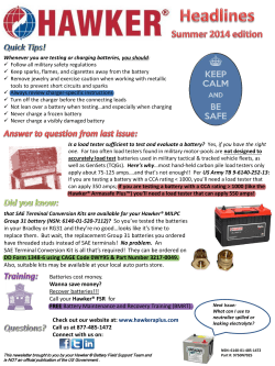
Summer 2014 - Hawker Battery | EnerSys
THERMO KING
CTEK MXT 14 ProfEssional 24v BaTTEry sUPPorT UniT (BsU) and
Ratio Relay Valve
RSK-145RC RING-CUT ROTO-SKINNER
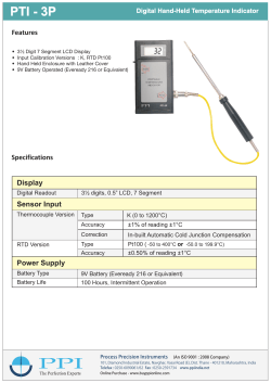
PTI - 3P - ppiindia.net
Press Release
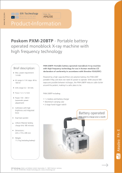
Poskom PXM-20BTP
Waterguard Home 5 Step Installation Guide
BATTERY CHARGERS AND TESTERS
© Copyright 2026 ExpyDoc
About ExpyDoc
DMCA / GDPR
Report