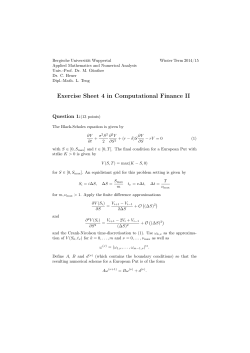
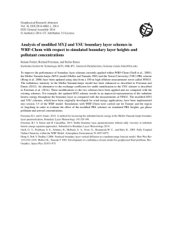
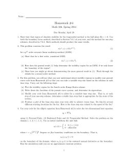
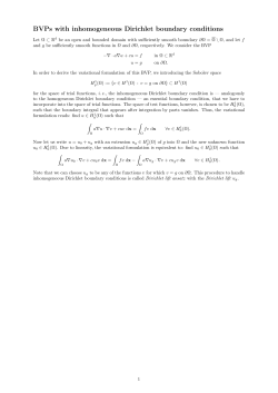
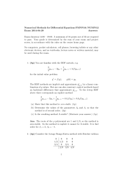
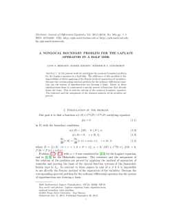
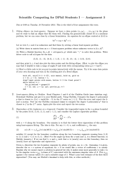
Practice note no. 07
Issued: March 2014
Designing for small lots
With the reduction of lot sizes and associated reduction
in road frontage widths, particular attention needs to be
given to the urban and engineering design of precincts and
subdivisions; incorporating small lots to ensure amenity,
functionality, legibility and safety, to avoid conflicts and
unnecessary costs and to simplify construction.
The following highlights development issues and
recommended best practice solutions for the urban and
engineering design for small lots in the context of the PDA
Residential 30 Guidelines.
Attention to detail in the coordination of services is essential
to avoid potential conflicts between services and with
driveways, due to the narrow frontages associated with most
small lots.
Critical issues
»» Zero lot line on low side, unless an integrated solution
»» Slope across small lots, unless integrated solution:
maximum 10 per cent across lot and 5 per cent
longitudinal
Small lot terraces (Fitzgibbon Chase)
»» Avoid cutting and retaining on the uphill side of
lots sloping steeply (more than 1 in 8) to the street,
particularly where side slope is present as this generally
results in diversion and concentration of overland flow
along fencelines to a point of weakness
»» Identify any natural depressions in the landform and
ensure overland flow to and within these is managed to
avoid nuisance to downstream properties.
On-street car parking
»» Narrow lots should be opposite larger lots where
possible
»» For rear lane lofts refer to PDA practice note no.12 Rear
»» Infrastructure clashes with zero lot lines and driveways.
Engineering and design issues
Small lots demand greater attention to detail with respect to
the location of services and infrastructure both with lots and
within the street verge.
Overland flow
Stormwater overland flow can be problematic for small lots
and requires particular attention.
»» Provide interallotment drainage
»» Avoid small lots below large drainage catchments
Designing for small lots
1
Lanes: design and development.
Streetscape issues
»» Small lots at end of street
»» Too many lots in a run (refer to PDA guideline no.05 neighbourhood planning and design)
»» Avoid single narrow lots amongst larger lots.
Water meters and conduits
»» Avoid clashes with driveways for zero lot line lots.
Power pillars
»» Where positioning adjacent to zero lot line boundaries cannot be avoided, avoid clashes with driveways for zero lot line
lots by offsetting to one side of boundary with adjacent lot
»» Power supply authority required minimum clearances to power supply pillars should be accommodated.
Communications pits
»» Avoid clashes with driveways for zero lot line lots, offset to suit.
Sewer manholes and roofwater pits
»» The preferred location for sewer and roofwater mains is within larger lots and along rear boundary
»» Avoid driveways
»» Avoid locating sewer and roofwater mains along zero lot line boundaries and within corner lots
»» Minimise sewers down longitudinal boundary, do not bench.
Footpaths
»» Should be constructed prior to driveways, to ensure continuity of pavement treatment and footpath crossfalls and to
provide priority to pedestrians and, where necessary, cyclists
»» Avoid cutting out the kerb by having a lower kerb profile.
Driveways
»» Driveways should be constructed to conform with and not replace footpaths
»» Driveway will typically be on the zero lot line boundary.
Street trees
»» Coordinate location of street trees with entry and driveway locations for zero lot line lots
»» Use substantial trees, 100 litre minimum, to promote survival during construction.
2
Designing for small lots
Small
- corner
lotslots
Smalllot
lotservicing
servicing
—corner
Zero Lot Lines
on downslope
boundary unless
integrated
solution.
RW
6.00
5.50
W
SW
Where sewer
and/or
roofwater are
located within
lots, locate
within larger
(non-ZLL) lots.
S
L
L
L
L
FA
L
FA
L
FA
L
L
FA
800mm
Zero
Lot
Line
SW
12.00
W
Zero
Lot
Line
10.00
10.00
DETAIL PLAN BELOW RW
S
SW
S
E
S
E
W
RW
E
RW
S
W
SW
RW
E
E
S
SW
SW
W
S
800mm
SW
E
S
12.50
(Wider lot to
accommodate
services
easement)
E
Legend
Stormwater
Detail Plan
SW
10.00
Stormwater Manhole
Roofwater
RW
Water Main
W
6.00
5.50
5.00
Water Conduit
Water Meter
Sewerage
S
E
Sewer Manhole
Electrical
Power Supply Pillar
Street Light
S
E
W
SW
RW
Lot Boundary
Footpath
Driveway
equal
equal
Trees located centrally between
property boundary and
driveway (clear of services)
Designing for small lots
3
Hydrants and valves
»» Preferably located opposite side boundaries of lots, or truncations, avoiding driveways.
Stormwater gullies
»» Preferably located mid-block or non-driveway locations for large lots
»» Avoid locating on driveway side of zero lot line boundary where known
»» Avoid using large/long backstones
»» Adoption of one way crossfall roads can minimize gullies on turning points and sags in internal access streets
»» No gully pits in front of small lots
»» Consider driveway access.
Bioretention pods
»» Preferred location is on park frontages, higher order streets or in medians
»» Undesirable in access streets
»» If unavoidable, locate on side without footpath, preferably on secondary frontage.
Pad mounted transformers
»» Plan well in advance and avoid visually intrusive locations, place in parks and open space and landscape out visual
impacts
»» Avoid locations along view lines
»» Avoid locations within lots
»» Should be shown on sales plans.
4
Designing for small lots
Small lot servicing - mid lots
Small lot servicing —mid lots
Service
connections
avoid driveways
10.00
W
SW
L
L
FA
L
FA
.80
RW
12.50
S
12.50
L
L
FA
E
E
5.00
Zero Lot Line
(ZLL)
SW
L
10.00
L
FA
5.00
6.00
Zero Lot Line
(ZLL)
5.50
Gullies to avoid
driveways
S
RW
E
L
RW
E
W
15.00
E
800mm
Zero Lot Line
(ZLL)
12.50
L
L
FA
L
L
FA
800mm
RW
S
W
Legend
Stormwater
SW
Stormwater Manhole
Roofwater
RW
Water Main
W
Water Conduit
Water Meter
Sewerage
S
Electrical
E
Power Supply Pillar
Street Light
Lot Boundary
Footpath
Driveway
Designing for small lots
5
Telecommunications units
»» Usually located within road reserve, however, as with pad mounted transformers, plan well in advance and avoid visually
intrusive locations, place in parks and open space and landscape out visual impacts
»» Avoid locations along view lines
»» Should be shown on sales plans.
Pad levels
»» Should be nominated with tolerance of +/- 100mm.
Retaining walls and boundary fences
»» Maximum height for retaining walls of 1.0m unless an integrated soloution
»» Combined height with boundary fence, maximum 2.4m
»» On zero lot lines, retaining wall feature treatment should extend to 100mm below nominated pad level for adjacent
downslope lot
»» Benching of sites at subdivison stage not required if slope criteria met.
6
Designing for small lots
Construction details options - Zero lot line housing
property boundary
property boundary
Gutter
Detail
Gutter
detail
Fascia
Built
to Boundary
Fascia
built
to boundary
Gutter detailGutter Detail
Set
Built to Boundary
Set back built
to Back
boundary
Designing for small lots
7
Side boundary detail - Concealed gutter built to boundary
Side Boundary Detail - Concealed Gutter Built to Boundary
Build to boundary
1st floor setback
1000mm min
(10-14.9m frontages)
Not to boundary setback
900mm min
(10-12.4m frontages)
1000mm
(12.5-14.9m frontages)
property boundary
1000mm max
Face brickwork or
painted render finish
100mm
min
PBL
Extend finsh below PBL
8
Designing for small lots
max fall
a
ccross s
ite 10
%
Side boundary detail - Conventional fascia gutter built to boundary
Side Boundary Detail - Conventional Fascia Gutter Built to boundary
Build to boundary
1st floor setback
1000mm min
(10-14.9m frontages)
Not to boundary setback
900mm min
(10-12.4m frontages)
1000mm
(12.5-14.9m frontages)
property boundary
1000mm max
Face brickwork or
painted render finish
max fall
a
ccross s
ite 10
%
100mm
min
PBL
Extend finsh below PBL
Designing for small lots
9
Side boundary detail - Recessed gutter built to boundary
Side Boundary Detail - Recessed Gutter Built to Boundary
Build to boundary
1st floor setback
1000mm min
(10-14.9m frontages)
Not to boundary setback
900mm min
(10-12.4m frontages)
1000mm
(12.5-14.9m frontages)
property boundary
1000mm max
Face brickwork or
painted render finish
100mm
min
PBL
Extend finsh below PBL
10
Designing for small lots
max fall
a
ccross s
ite 10
%
Footing detail - built to boundary
1000mm max
property boundary
max c
ross fa
ll 1
0%
Extend face finish
min 100mm below PBL
1000mm max
PBL
Footing Detail - Built to Boundary
Designing for small lots
11
Zero lot lines
»» On low side unless an integrated solution.
Speed control devices and roundabouts
»» Special attention at speed control devices and roundabouts
»» To ensure safe and convenient access to lots, these should be located such that they are clear of driveways or small lots. If
this cannot be avoided, driveways should be constructed as part of the subdivision works to provide safe and convenient
access.
»» In all other cases, driveway access at speed control devices should be prohibited
»» Utilise features, such as trees
»» Landscape within speed control devices.
Rear lanes
»» Where possible, avoid locating utility services within laneways
»» Where utility services within laneways cannot be avoided, they will generally be required to be located within an unpaved
section of laneway along the edge of the trafficable surface
»» Refer to Rear Lane Practice Note for further details.
Flush kerb detail
»» Flush kerb should be provided to the low side edge of one-way crossfall pavements where fall is to swale or open space
and pavements with no kerb and channel
»» Flush kerb in this application should have chamfer or radius providing a 40mm difference in elevation from pavement edge
to verge to minimize siltation and drainage problems
»» Bollards may be required for driver safety.
Street lights
»» Required within laneways over 60 metres for safety, preferably mid block
»» Avoid locating on boundary of small lots, preferably locate on boundary of large lots.
12
Designing for small lots
Common trenching
Common trenching, or shared service allocation, is encouraged and, involves the provision of a number of services within one
trench or service allocation area.
The advantages of common trenching include:
»» elimination of a number of single trenches, each with its own construction, settlement and reinstatement problems
»» accurate location of services for possible repair or maintenance
»» reduced verge width
»» increased verge width available for tree planting and/or landscaping
»» less conflict between services as depth relativities are known
»» more efficient use of construction equipment
»» reduced verge and footpath disturbance for earlier establishment.
Typical common trenching diagram
Kerb d
an nel
n
Cha
ing
Road
t
Plan
ath
p
Foot
ch
Tren
Tree g
chin
Tren
BN
s/N
m
Com
ral G
Natu
as M
ain
HV
LV
Typical Common Trenching Diagram
Designing for small lots
13
Boundary setbacks for sloping sites
Boundary
Boundarysetback
Setback
specified
ReferintoPlan
DA of
Development
Boundary
setback
Boundary Setback
specified
Refer in
to Plan
DA of
Development
300mm 300mm
min min
300mm
min
1m max
property boundary
max fall accr
oss site 10%
PBL
Boundary Setbacks For Sloping Sites
14
Designing for small lots
© Copyright 2026 ExpyDoc