Citect for Windows
Driver User Configuration
ABRSLinx Driver
Author
Date
Comment
Paul Sutcliffe
10/06/1998
Original
30/07/1998
Modification
Alex Chan
10/11/1999
Modification
Graeme Sutton
20/01/2000
Modification
Anna McIntyre
09/08/2000
Added driver specific error codes
Graeme Sutton
15/02/2001
Changed and added examples in section 3.5
Stephen Straton
2 Nov. 01
Added note about RSLinx starting/stopping.
Carol Jia
8 Jan. 02
Added the “Status” in the citect.ini
Driver User Configuration
Contents
1
INTRODUCTION
4
1.1 Abbreviations/Glossary
4
2 TARGET DEVICE(S) AND PROTOCOL
3
6
2 .1 Introduction
6
2.2 Device Manufacturer
6
2.3 Device Definition
6
2.4 Software Configuration
6
2.5 The Role of RSLinx
6
2.6 Common Connection Name Prefixes in RSLinx
6
2.7 Installation and configuration of the RSLinx application.
2.7.1 Requirements
2.7.2 Installation and licensing
2.7.3 Configuration of the RSLinx application.
7
7
7
7
2.8 Maximum Request Length
8
USER INTERFACE
9
3.1 Driver Name
9
3.2
Boards Form
Board Type
3.2.1
Address
3.2.2
IO Port
3.2.3
Interrupt
3.2.4
Special Opt
9
9
9
9
9
9
3.3
Ports Form
3.3.1
Baud Rate
3.3.2
Data Bits
3.3.3
Stop Bits
3.3.4
Parity
3.3.5
Special Opt
9
9
9
9
9
9
3.4
IO Devices Form
3.4.1
Protocol
3.4.2
Address
10
10
10
ABRSLINX.DOC
2
Driver User Configuration
3.5
Examples of Drivers and IO device address
3.5.1 Using the 1756 ControlLogix Ethernet module to connect CITECT to a PLC on a DH+ network
(figures 3.5.1a, 3.5.1b, 3.5.1c)
3.5.2 Using the 1756 ControlLogix DH+ module to connect CITECT to a PLC on another DH+
network (figures 3.5.2, 3.5.1b)
3.5.3 Directly connecting to a PLC via DH+ network
3.5.4 Directly connecting to a PLC via Ethernet
3.5.5 Directly connecting to a PLC using RS232
3.5.6 Using the 1756 ControlLogix Ethernet module to connect CITECT to a PLC on a ControlNet
network connected to the 1756 ControlLogix CNB module.
3.5.7 Using the 1756 ControlLogix ControlNet module to connect CITECT to a PLC on a DH+
network.
12
3.6 Device Variable Types
3.6.1 SLC-500 Series IO Device Variable Types
3.6.2
PLC-5 IO Device Variable Types
3.6.3
PLC-5/250 Pyramid Integrator IO Device Variable Types
3.6.4 PLC-3 IO Device Variable Types (Not Tested)
3.6.5 PLC-2 IO Device Variable Types (Not Tested)
17
17
18
19
21
23
3.6
Parameters and INI options
3.6.1
Standard Parameters
3.6.2
PROTDIR.DBF
24
24
24
3.7
25
Driver Specific Errors
3.8 Debug Messages
ABRSLINX.DOC
12
14
15
15
15
16
16
25
3
Driver User Configuration
1
Introduction
1.1 Abbreviations/Glossary
A-B Network
Proprietary Allen-Bradley communications network.
AB_DF1
The RSLinx serial communications driver.
AB_ETH
The RSLinx Ethernet driver for communication to the PLC-5 Ethernet
modules and 5820-EI modules.
AB_KTC
The RSLinx ControlNet driver. For use with the 1784-KTC(X) card under
Windows NT.
AB_KTC95
The RSLinx ControlNet driver. For use with the 1784-KTC(X) card under
Windows 95.
ABRSlinx
A Citect driver designed to interface with the Rockwell RSLinx application and communicate with Allen-Bradly controllers.
API
Application Programming Interface.
ASA
Advanced System Architecture, The driver used to support the Controllogix 1756 Ethernet module.
ControlNet
A deterministic, high speed control and I/O network.
ControlLogix 1756
An Allen-Bradley control system consisting of a chassis, power supply an
various communications modules, including but not limited to Ethernet,
Controlnet and Data Highway Plus. PLC modules are also to be introduced.
DF1
EIA RS-232 full duplex protocol.
DH-485
An A-B network that uses EIA RS-485 protocol.
DH
Data Highway network.
DH+
Data Highway Plus network.
DH/DH+
Data Highway and/or Data Highway Plus.
EI
Ethernet Interface module.
Ethernet Processor
PLC-5/20E, PLC-5/40E, PLC-5/80E.
ei_name
host name for the EI
INTERCHANGE
A-B API Software Library for host computers, Superseded by RSLinx.
KA module
PI DH/DH+ interface module (5130-KA)
KT
Communications interface module
LP
Logic processor
local station
A station connected directly to an A-B or Ethernet network
local
The station which contains the ethernet interface
off-link addressing
A method of specifying the station address of a remote station.
remote
A station connected to the ethernet interface via DH/DH+ link
RDLG
Remote Device via Linx Gateway The RSLinx driver used to Support
communication to1756 ControlLogix devices.
RSI
Rockwell Software International.
ABRSLINX.DOC
4
Driver User Configuration
RSLinx
An applications program to facilitate the control of a range of AllenBradley PLC’s and a range of RockWell Software products.
RSLinx-lite
A “cut down” version of RSLinx. Bundled with many RSI and AB products.
RSLinx-OEM
An applications program to facilitate the control of a range of AllenBradley PLC’s. RSLinx-OEM is a subset of RSLinx.
RSLinx SDK
A Software Development Kit for the RSLinx API .
PCCC
Programmable Controllers Communications Command. The set of
commands that Allen-Bradley controllers use to communicate over networks
PI
Pyramid Integrator system
PLC
Programmable Logic Controller
RM module
PI Resource Manager module
RS module
PI Remote Scanner module
SLC
Small Logic Controller (SLC 500, 5/01, 5/02, 5/03, 5/04)
station number
address of a device on an A-B network
ABRSLINX.DOC
5
Driver User Configuration
2 Target Device(s) and Protocol
2 .1 Introduction
This section defines the types of I/O Devices that are targeted by this driver.
2.2 Device Manufacturer
Allen-Bradley, A Rockwell International Company
2.3 Device Definition
The ABRSlinx driver provides communication to the following Allen-Bradley devices:
PLC5/250
SLC500
PLC5
Connection can be direct or via the 1756 ControlLogix Ethernet port.
2.4 Software Configuration
The ABRSlinx driver acts as a layer of software between Citect and the RSlinx software library.
The driver assumes that RSLinx is configured correctly. If RSLinx is not running when the Citect
runtime is started then the driver will start it. On runtime shutdown Citect will not stop RSLinx,
this is because RSLinx might be in use by another application.
2.5 The Role of RSLinx
RSlinx is an applications program designed to facilitate communications with a range of AllenBradley programmable logic controllers. RSLinx also provides an API to its software library and
thus allows third party applications; in this case Citect, to communicate with these controllers.
The interface provided is uniform across a range of drivers and networks. RSLinx comes in several “packages” RSLinx ,RSlinx-OEM and RSlinx-lite. The RSLinx lite does not provide the necessary interface to third party software and so is unsuitable for the Citect ABRSLinx driver. The
Citect Driver ABRSLinx was written using Rockwell Software RSLinx C SDK Version 1.70.62 Cat
9355-WABC.
2.6 Common Connection Name Prefixes in RSLinx
TCP This provides a connection to the ControlLogix 1756 Ethernet port.
AB_ETH This provides an Ethernet connection to Allen-Bradley PLC-5/80E, PLC-5/40E, PLC5/20E, and the 5820-EI.
AB_KTC This provides a ControlNet (release 1.25 or higher) interface using the 1784-KTC(X)
hardware on windows NT
AB_KTC95 This provides a ControlNet (release 1.25 or higher) interface using the 1784-KTC(X)
hardware on Windows 95
AB_DEF1 This provides an RS-232 serial connection to Allen-Bradley DF1 serial devices.
ABRSLINX.DOC
6
Driver User Configuration
The ABRSLinx driver does not preclude use of other drivers supported by the RSlinx.
2.7 Installation and configuration of the RSLinx application.
Installation
2.7.1 Requirements
1 The RSLinx or RSLinx-OEM application.
2 The serial number provided with the application.
3 If using Windows NT admin privileges will be required.
4 The AB software master disk key disk to fully licence RSLinx.
5 Approximately 12 MB of free disk space.
2.7.2 Installation and licensing
Run the setup program on disk 1 and follow the instructions. The installation program is painless.
Run the evmove program on the master licence disk to licence RSLinx. This program copies a
“TOKEN” or software key to your hard drive. Without this key you can only run RSLinx-lite and
so, will be unable to use the ABRSLinx driver.
2.7.3 Configuration of the RSLinx application.
Each driver that is to be used by ABRSLinx must first be configured using the RSLinx
|Communication Configure Driver Dialogue box.
To configure a driver. Select it from the available drivers list.
Click the “Add New” button.
Fig 2.7.3a RSLinx Driver configuration.
The driver edit dialogue box will be displayed.
Type a connection name or click ok to accept the default.
Complete the configuration dialog box.
When finished adding all devices, all connection names are displayed in the main window.
ABRSLINX.DOC
7
Driver User Configuration
Fig 2.7.3b RSLinx main window
2.8 Maximum Request Length
The Maximum request length for the ABRSLINX protocol is 1824 bits.
ABRSLINX.DOC
8
Driver User Configuration
3 User Interface
This section defines how the user will see the driver. This relates directly to how the Citect forms
need to be filled out and any special INI options. For the kernel, the debug trace messages and
the Stats Special counters are documented
3.1 Driver Name
ABRSLINX
3.2 Boards Form
Board Type
ABRSLINX
3.2.1
Address
0.
3.2.2
IO Port
Not used.
3.2.3
Interrupt
Not used
3.2.4
Special Opt
Not used.
3.3 Ports Form
One port is declared for each RSlinx connection name that Citect is using.
3.3.1
Baud Rate
Not used.
3.3.2
Data Bits
Not used.
3.3.3
Stop Bits
Not used.
3.3.4
Parity
Not used
3.3.5
Special Opt
The RSLinx connection name that this port is to use. The list of configured drivers can be seen is
the RSLinx Configure drivers dialogue box. This box is accessible from the Configurations menu
option Configure drivers. The default format is DriverName-X where X is the connection number.
For example:
TCP-1 for the first configured 1756 ControlLogix Ethernet port driver.
AB_DF1-1 to use the first configured DF1 driver. Local connection serial communication.
AB_ETH-1 to use the first configured Ethernet driver. Local connection using Ethernet to PI or
5820-EI
ABRSLINX.DOC
9
Driver User Configuration
AB_ETH-2 to use the second configured Ethernet driver. Local connection using Ethernet to PI
or 5820-EI
AB_ KTC-1 to use the first configured ControlNet driver. Under Windows NT
AB_KTC95-1 to use the first configured ControlNet driver. Under Windows 95.
3.4 IO Devices Form
3.4.1
Protocol
One of the following.
ABRSLINX5 for the PLC 5 processor
ABRSLINX250 the PLC 250 processor (Pyramid Integrator)
ABRSLINX500 The SLC 500 processor
3.4.2
Address
AB:KEYWORD[/B:b/L:l/G:g/P:p/M:m/C:c/E:e],StationNumber/Ss
Where KEYWORD is one of :
NAME, LOCAL, LONGLOCAL, OFFLINK, PIGATEWAY,
PIGATEWAYIP, PIGATEWAYNAME, DF1MASTER, ASA, CIP
The keyword LOCAL is used for devices directly connected to your PC via RS232 or Data Highway.
The Keyword ASA is used for devices connected via the 1756 ControlLogx Ethernet module.
The Keyword NAME is used for devices directly connected to your PC via Ethernet.
The keyword OFFLINK is used for devices connected via the 1756 DHRIO ControlLogix Data
Highway module.
The keyword CIP is used for devices connected via the 1756 CNB ControlLogix Control Net
module.
The following fields are valid only with the keywords OFFLINK, PIGATEWAY, PIGATEWAYIP,
PIGATEWAYNAME, and ASA.
Field
Description
Valid Values
/L:l
destination link id
tool. (which uses decimal)
0 - 177777 (octal) This is set in the module using the 1756gtwy
/B:b
bridge address 1 - 376 (octal)
/G:g
gateway to final DH485 link
/P:p
pushwheel number
/M:m
module type
/C:c
channel number
/E:e
Ethernet interface station number
1 - 376 (octal)
0 - 8 (decimal)
KA, KT, RM
0, 2, 3
0 – 77 (octal)
/KA
bridge requires 1785-KA addressing mode
through a 1785-KA from DH+ to DH.
ABRSLINX.DOC
/KA switch is required to communicate
10
Driver User Configuration
/Ss
the driver will monitor a user defined address every watchtime and if the user specified condition fails, then a driver_offline error or similar is returned to Citect. This will then force a swap to the
redundant unit.
For this to work correctly, you may need to manually configure the status register in your PLC.
The register must be configured as follows, depending on whether it is a digital or analog variable:
Digital - The variable must always be on, otherwise the unit is put offline.
Analog - The variable must be changed for each read. If the variable has not changed since the
last read, the unit is put offline.
Allowable Values
The value for this parameter must be formatted as follows: <RawType>, <BitWidth>,<UnitType>, <UnitAddress>,<UnitCount>,
where:
RawType =
0 for Digital
1 for Int
4 for Long
8 for Byte
BitWidth =
1 for Digital
8 for Byte
16 for Int
32 for Long
UnitType = Protocol specific. See the variable specification .DBF files for the particular PLC.
UnitAddress= The item number or bit number.
UnitCount =
1 for Analog
16 for Digital
Default Value No default.
StationNumber string
StationNumber string specifies the station number of a remote processor on an A-B network.
ControlLogix 1756 DHRIO Station number.
In the case of the 1756 ControlLogix DHRIO Module connection the Station number is a path
string
P.S.C.R
Where P is a port number and is always 1.
S is the slot number in the ControlLogix chassis to which the DHRIO module connected. The slot
numbers start a 0 and are counted from the left hand side chassis as you face the module. So for
example the first module on the left hand side of the chassis is 0 the second 1 etc.
C is the connector number in the 1756 DHRIO module connector A is 2 connector B is 3.
R is the DH+ station number of the remote PLC to which you are communicating. This is set in
the remote device using its programming software or by switch settings. The station number is in
decimal.
ABRSLINX.DOC
11
Driver User Configuration
For example
1.2.3.63 is for slot 2 (third spot from the left) ControlLogix DHRIO module connector B. The remote PLC has a DH+ station number of 77 octal.
ControlLogix 1756 ControlNet CNB Station number
In the case of the 1756 ControlLogix CNB module connection the Station number is a path string
1.S.2.R
Where 1 is the number 1 and is used to indicate the following number is a slot number.
S is the slot number in the ControlLogix chassis to which the CNB module connected. The slot
numbers start a 0 and are counted from the left hand side chassis as you face the module. So for
example the first module on the left hand side of the chassis is 0 the second 1 etc.
2 is the number 2 and is used to indicate the following number is a MAC number.
R is the remote devices Control net MAC id.
Other A-B Network Valid Station Numbers
Data Highway 1 to 376 (octal) inclusive
Data Highway Plus
0 to 77 (octal) inclusive
DH485 0 to 37 (octal) inclusive
RS-232 (DF1) 0 to 77 (octal) inclusive
Local Ethernet Ethernet address
When defining data items on a local Ethernet processor, you must omit the station number.
3.5 Examples of Drivers and IO device address
3.5.1 Using the 1756 ControlLogix Ethernet module to connect CITECT to a PLC on a DH+
network (figures 3.5.1a, 3.5.1b, 3.5.1c)
A SLC 5/04 with station address 1 is connected to a DH+ network. The 1756 ControlLogix
DHRIO module channel A (Number 2) has been configured with a link ID of 20. This module is in
slot 2 of the 1756 ControlLogix Chassis.
The board type is ABRSLINX
The port special option is the connection name in RSLINX (eg. TCP-1)
The protocol is ABRSLINX500
The IODevice address is AB:ASA/L:24,1.2.2.1
ABRSLINX.DOC
12
Driver User Configuration
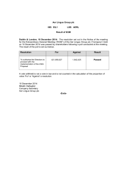
Fig 3.5.1a Using the 1756 ControlLogix Ethernet module to connect CITECT to a PLC on a DH+
network.
Fig 3.5.1b 1756gtwy configuration tool view of 1756 ControlLogix DHRIO module settings used
in this example.
ABRSLINX.DOC
13
Driver User Configuration
Fig 3.5.1c Citect settings used in the above example
3.5.2 Using the 1756 ControlLogix DH+ module to connect CITECT to a PLC on another
DH+ network (figures 3.5.2, 3.5.1b)
An SLC 5/04 with station address 6 is connected to a DH+ network. The 1756 ControlLogix
DHRIO module channel A (Number 2) has been configured with a link ID of 20 and a DH+ address of 5. The 1756 ControlLogix DHRIO module channel B (Number 3) has been configured
with a link ID of 30 and a DH+ address of 4. This module is in slot 2 of the 1756 ControlLogix
chassis. The SLC is connected to channel B if this module. A KTX card with local DH+ address
of 77 has been installed in the PC and is connected to Channel A.
The driver used is ABRSLINX
The port special option is the connection name in RSLINX (eg. AB_KT-1)
The protocol is ABRSLINX500
In the Citect I/O devices form enter an address of AB:OFFLINK/B:5/L:36,1.2.2.6
ABRSLINX.DOC
14
Driver User Configuration
Fig 3.5.2 Using the 1756 ControlLogix DH+ module to connect CITECT to a PLC on another
DH+ network.
3.5.3 Directly connecting to a PLC via DH+ network
A PLC5/40 with local DH+ address 3 and a KTX card installed in PC.
The board type is ABRSLINX
The port special option is the connection name in RSLINX (eg. AB_KT-1)
The protocol is ABRSLINX5
In the Citect I/O devices form enter an address of AB:LOCAL,3
3.5.4 Directly connecting to a PLC via Ethernet
A SLC 5/40 with Ethernet address 192.168.2.76
The board type is ABRSLINX
The port special options is connection name in RXLINX (eg. AB_ETH-1)
The protocol is ABRSLINX5
In the Citect I/O devices form enter an address of AB:NAME,192.168.2.76
3.5.5 Directly connecting to a PLC using RS232
A local SLC 5/04 station number 1 is connected via RS232. The RSLinx AB_DF1-1 driver has
been configured.
The board type is ABRSLINX
The port is the connection name in RSLINX (eg. AB_DF1-1)
The protocol is ABRSLINX500
In the Citect I/O Devices form enter an address of AB:LOCAL,1
ABRSLINX.DOC
15
Driver User Configuration
3.5.6 Using the 1756 ControlLogix Ethernet module to connect CITECT to a PLC on a ControlNet network connected to the 1756 ControlLogix CNB module.
A PLC5/40 with station address 2 is connected to a ControlNet network. The 1756 ControlLogix
CNB is in slot 4 of the 1756 ControlLogix Chassis.
The board type is ABRSLINX
The port special options is the connection name in RSLINX (eg. TCP-1)
The protocol is ABRSLINX5
In the Citect I/O devices form enter an address of AB:ASA,1.4.2.2
3.5.7 Using the 1756 ControlLogix Ethernet module to connect CITECT to a ControlLogix
PLC in the same ControlLogix Gateway.
A ControlLogix Logix5550 PLC is in Slot 0 of the ControlLogix Gateway.
Notes: i. Citect can only communicate to Controller Tags configured as PLC5 mappings in the
RSLogix PLC program.
ii. A mapping for File 0 must exist for the driver to bring the unit online.
iii. Each mapping can only be to one tag or one array and each mapping is a separate
read request, so it is recommended that arrays are used as much as possible.
iv. The controller response time degrades quickly as the number of mappings increases,
so this protocol is not recommended other than for reading a small number of Tags or arrays.
The board type is ABRSLINX
The port special option is the name of the connection in RSLinx (eg. AB_TCP-1)
The protocol is ABRSLINX5
In the Citect I/O devices form enter an address of AB:ASA,1.0 (ie. uses the format P.S)
3.5.8 Using the 1756 ControlLogix ControlNet module to connect CITECT to a PLC on a
DH+ network.
An SLC 5/04 with station address 6 is connected to a DH+ network. The 1756 ControlLogix
DHRIO module channel A (Number 2) has been configured with a link ID of 20 and a local DH+
address of 5 (see figure 3.5.1b). This module is in slot 2 of the 1756 ControlLogix chassis. The
1756 ControlLogix CNB module channel A (Number 2) has been configured with MAC ID 5. This
module is in slot 3 of the 1756 ControlLogix chassis. A KTC card with local MAC ID 7 has been
installed in the PC and is connected to channel A of the CNB module.
The board type is ABRSLINX
The port special option is the name of the connection in RSLinx (eg. AB_KTC-1)
The protocol is ABRSLINX500
In the Citect I/O devices form enter an address of AB:CIP/L:24,2.5.1.3.2.6 (ie. uses the format
2.M.P.S.C.R)
ABRSLINX.DOC
16
Driver User Configuration
3.6 Device Variable Types
3.6.1 SLC-500 Series IO Device Variable Types
Device data
type
Citect
data type
Address range
Description/Special Usage/Limitations
O:s.n
INT
s=0-30, n=0-255
Output Image (see error section)
O:s.n/b
DIGITAL
s=0-30, n=0-255, b=0-15
Output Image
I:s.n
INT
s=0-30, n= 0-255
Input Image (see error section)
I:s.n/b
DIGITAL
s=0-30, n=0-255, b=0-15
Input Image
S:n
INT
n=0-255
Status (range depends on processor
Tf:n.*
INT
f=4,10-255, n=0-255
Timer, * = {PRE, ACC}
Tf:n.*
DIGITAL
f=4,10-255, n=0-255
Timer, * = {DN, TT, EN}
Tf:n/b
DIGITAL
f=4,10-255, n=0-255, b=0-15
Timer Status/Control bits
Cf:n.*
INT
f=5,10-255, n=0-255
Counter, * = {PRE, ACC}
Cf:n.*
DIGITAL
f=5,10-255, n=0-255
Counter, * = {UN, OV, DN,CD,
CU}
Cf:n/b
DIGITAL
f=5,10-255, n=0-255, b=0-15
Counter Status/Control bits
Rf:n.*
INT
f=6,10-255, n=0-255
Control, * = {LEN, POS}
Rf:n.*
DIGITAL
f=6,10-255, n=0-255
Control, * = {FD, IN, UL, ER, EM,
DN, EU, EN}
Rf:n/b
DIGITAL
f=6,10-255, n=0-255, b=0-15
Control Status/Control bits
Bf/b
DIGITAL
f=3,10-255, b=0-32767
Binary bits
Bf:n/b
DIGITAL
f=3,10-255, n=0-255 b=0-15
Binary bits
Nf:n
INT
f=7,10-255, n=0-255
Integer Image
Nf:n/b
DIGITAL
f=7,10-255, n=0-255, b=0-15
Integer bit Image
REAL
f=7,10-255, n=0-255
Floating Point Image
Ff:n/b*2
DIGITAL
f=7,10-255, n=0-255, b=0-32
Floating Point Image
Af:n
INT
f=10-255, n=0-255
Ascii Image, High byte and low
byte contain 1 char each.
STf:n*2
STRING
f=10-255, n=0-255
String
Ff:n
*2
Table 3.6.1
Note: 2 not supported on SLC 500, 5/01, 5/02, 5/03 processors.
ABRSLINX.DOC
17
Driver User Configuration
3.6.2
PLC-5 IO Device Variable Types
Device data
type
Citect
data type
Address range
Description/Special Usage/Limitations
O:rg
INT
r=0o0-0o27*1, g=0o0-0o7,
Output Image (r = i/o rack #, g =
i/o group #)
O:rg/x
DIGITAL
r=0o0-0o27*1, g=0o0-0o7,
x=0o0-0o17
Output Image (r = i/o rack #, g =
i/o group #, x = bit #)
I:rg
INT
r=0o0-0o27*1, g=0o0-0o7,
Output Image (r = i/o rack #, g =
i/o group #)
I:rg/x
DIGITAL
r=0o0-0o27*1, g=0o0-0o7,
x=0o0-0o17
Output Image (r = i/o rack #, g =
i/o group #, x = bit #)
S:n
INT
n=0-128*1
Status word
*1,
S:n/b
DIGITAL
n=0-128 b=0-15
Status bits
Bf:n
INT
f=3,9-999, n=0-999
Binary bits
Bf/b
DIGITAL
f=3,9-999, b=0-32767
Binary bits
*2,
Bf:n/b
DIGITAL
f=3,9-999, n=0-999 b=0-15
b=0o0-0o17*2
Binary bits
Nf:n
INT
f=7,9-999, n=0-999
Integer Image
Nf:n/b
DIGITAL
f=7,9-999, n=0-999, b=0-15
Integer bit Image
Ff:n
REAL
f=8-999, n=0-999
Floating Point Image
Ff:n/b
DIGITAL
f=8-999, n=0-999, b=0-32
Floating Point Image
Af:n
INT
f=9-999, n=0-999
Ascii Image, High byte and low
byte contain 1 char each.
Df:n
INT
f=9-999, n=0-999
BCD Image
STf:n
STRING
f=9-999, n=0
String Image, :0 specifies length
of string, maximum of 82 BYTES
of data accessible only by addressing whole structure.
Tf:n.*
INT
f=4,9-999, n=0-999
Timer, * = {PRE, ACC}
Tf:n.*
DIGITAL
f=4,9-999, n=0-999
Timer, * = {DN, TT, EN}
Cf:n.*
INT
f=5,9-999, n=0-999
Counter, * = {PRE, ACC}
Cf:n.*
DIGITAL
f=5,9-999, n=0-999
Counter, * = {UN, OV, DN,CD,
CU}
Rf:n.*
INT
f=6,9-999, n=0-999
Control, * = {LEN, POS}
Rf:n.*
DIGITAL
f=6,9-999, n=0-999
Control, * = {FD, IN, UL, ER, EM,
DN, EU, EN}
SCf:n.*
INT
f=9-999, n=0-999
Sequential Function Chart, * =
{PRE, TIM}
SCf:n.*
DIGITAL
f=9-999, n=0-999
SFC Status * = {DN, ER, OV, LS,
FS, SA}
ABRSLINX.DOC
18
Driver User Configuration
Device data
type
Citect
data type
Address range
Description/Special Usage/Limitations
BTf:n.*
INT
f=9-999, n=0-999
Block Transfer, * = {RLEN, DLEN,
FILE, ELEM, RGS}
BTf:n.*
DIGITAL
f=9-999, n=0-999
Block Transfer * = {RW, TO, NR,
EW, CO, ER, DN, ST, EN}
PDf:n.*
INT
f=9-999, n=0-999
PID Block, * =
{SP,KP,KI,KD,BIAS,MAXS,MINS,
DB,SO,MAXO,MINO,UPD, PV,
ERR, OUT, PVH, PVL, DVP,
DVN,PVDB,DVDB,MAXI,MINI,TI
E, DATA}
PDf:n.*
DIGITAL
f=9-999, n=0-999
PID Block * =
{PE,MO,CA,SWM,DO,PVT,CL,C
T,EN,PVHA,PVLA,DVPA,DVNA,
EWD,OLH,OLL,SPOR,INI}
MGf:n.*
INT
f=9-999, n=0-999
Message Control, * =
{ERR,RLEN,DLEN,DATA}
MGf:n.*
DIGITAL
f=9-999, n=0-999
Message Control * =
{EW,CO,ER,DN,ST,EN,TO,NR}
Note 1: range processor dependent,
Table 3.6.2
3.6.3
PLC-5/250 Pyramid Integrator IO Device Variable Types
Device data
type
Citect
data type
Address range
Description/Special Usage/Limitations
xBf:n
INT
x=0-4, f=0-9999, n=0-9999
Binary File {-32768 to 32767}
xBf:n/b
DIGITAL
x=0-4, f=0-9999, n=0-9999,
b=0-15
Binary bits
xNf:n
INT
x=0-4, f=0-9999, n=0-9999
Integer File {-32768 to 32767}
xNf:n/b
DIGITAL
x=0-4, f=0-9999, n=0-9999,
b=0-15
Integer bits
x=0 Resource Manager
x=1-4 Logic Processor(s)
xLf:n
LONG INT
x=0-4, f=0-9999, n=0-9999
Long Integer File
{-2,147,483,648 to 2,147,483,647}
xLf:n/b
DIGITAL
x=0-4, f=0-9999, n=0-9999,
b=0-31
Long Integer bits
xFf:n
REAL
x=0-4, f=0-9999, n=0-9999
Floating point number File
{+/- 3.4028E+38}
xFf:n/b
ABRSLINX.DOC
DIGITAL
x=0-4, f=0-9999, n=0-9999,
b=0-31
Floating point number bits
19
Driver User Configuration
Device data
type
Citect
data type
Address range
Description/Special Usage/Limitations
xTf:n.*
LONG
x=0-4, f=0-9999, n=0-9999
Timer File
* = {PRE, ACC}
xTf:n.*
DIGITAL
x=0-4, f=0-9999, n=0-9999
Timer File
* = {DN, TT, EN}
xSTf:n
STRING
x=0-4, f=0-9999, n=0-9999
String Image, :0 specifies length
of string, maximum of 82 BYTES
of data accessible only by addressing whole structure.
eg. ST12:6
xCf:n.*
INT
x=0-4, f=0-9999, n=0-9999
Counter, * = {PRE, ACC}
xCf:n.*
DIGITAL
x=0-4, f=0-9999, n=0-9999
Counter, * = {UN, OV, DN,CD,
CU}
xRf:n.*
INT
x=0-4, f=0-9999, n=0-9999
Control, * = {LEN, POS}
xRf:n.*
DIGITAL
x=0-4, f=0-9999, n=0-9999
Control, * = {FD, IN, UL, ER, EM,
DN, EU, EN}
xPDf:n.*
INT
x=0-4, f=0-9999, n=0-9999
PID Block, * =
{SP,KP,KI,KD,BIAS,MAXS,MINS,
DB,SO,MAXO,MINO,UPD, PV,
ERR, OUT, PVH, PVL, DVP,
DVN,PVDB,DVDB,MAXI,MINI,TI
E, DATA ???, ADDR}
xPDf:n.*
DIGITAL
x=0-4, f=0-9999, n=0-9999
PID Block * =
{PE,MO,CA,SWM,DO,PVT,CL,C
T,EN,PVHA,PVLA,DVPA,DVNA,
EWD,OLH,OLL,SPOR,INI}
XMSGf:n.*
INT
x=0-4, f=0-9999, n=0-9999
Message Control, * =
{ERR,RLEN,DLEN,DATA}
XMSGf:n.*
DIGITAL
x=0-4, f=0-9999, n=0-9999
Message Control * = { ER, DN,
EW, CO, AE, AD, ST, EN}
S:n
STRING
x=0-4, n=0-614(RM), n=019(LP)
System Public Status (RM)
r=0o0-0o37, g=0o0-0o7,
n=0o0-0o377, b=0o0-0o17
Output Image
O:rg.n/b
DIGITAL
Module Public Status (LP)
r = I/O rack
g = I/O group
(not accessible as word)
XMSGf:n.*
ABRSLINX.DOC
DIGITAL
x=0-4, f=0-9999, n=0-9999
Message Control * = { ER, DN,
EW, CO, AE, AD, ST, EN}
20
Driver User Configuration
Device data
type
Citect
data type
Address range
Description/Special Usage/Limitations
IS:n/b
DIGITAL
n=0o0-0o777, b=0o0-0o17
n=scanner for racks
000-177 for I/O racks 00-07
200-377 for I/O racks 10-17
400-577 for I/O racks 20-27
600-777 for I/O racks 30-37
Available on I/O scanner modules
only
SBTDf:n/b
DIGITAL
s=1-4, f=0-254, n=0-255, b=015
Block Transfer Data Files
s = 1 for I/O racks 00-07
s = 2 for I/O racks 10-17
s = 3 for I/O racks 20-27
s = 4 for I/O racks 30-37
Note
1: range processor dependant,
2: x = module number, 0 reserved for Resource Manager, 1-4 for Logic Processor(s)
Table 3.6.3
3.6.4 PLC-3 IO Device Variable Types (Not Tested)
Device data
type
Citect
data type
Address range
Description/Special Usage/Limitations
Bf:n
INT
f=0-999, n=0-9999
Binary File {- 32768 to 32767}
Bf:n/b
DIGITAL
f=0-999, n=0-9999, b=0o00o17
Binary bits
Nf:n
INT
f=0-999, n=0-9999
Integer File
Nf:n/b
DIGITAL
f=0-999, n=0-9999
Integer bits
b=0o0-0o17
Df:n
INT
f=0-999, n=0-9999
BCD File
Df:n/b
DIGITAL
f=0-999, n=0-9999, b=0o00o17
BCD bits
Sf:n
INT
f=0-999, n=0-9999
Status File
Sf:n/b
DIGITAL
f=0-999, n=0-9999, b=0o00o17
Status bits
Af:n
INT
f=0-999, n=0-9999
Ascii char 2 char / word
Af:n/b
DIGITAL
f=0-999, n=0-9999, b=0o00o17
Ascii char 2 char / word
Hf:n
LONG
f=0-999, n=0-9999
High Order Interger
Hf:n/b
DIGITAL
f=0-999, n=0-9999, b=0o00o37
High Order Interger {-2147483648
to 2147483647}
ABRSLINX.DOC
21
Driver User Configuration
Device data
type
Citect
data type
Address range
Description/Special Usage/Limitations
P*:p
INT
p=0-9999
Pointer file/word
* = {FIL,WRD}
P*:p/b
INT
p=0-9999, b=0o0-0o17
Pointer file/word
* = {FIL,WRD}
(not supported)
Ff:n
REAL
f=0-999, n=0-9999
Long Integer File
Ff:n/b
DIGITAL
f=0-999, n=0-9999, b=0o00o37
Long Integer bits
TCTL:n/*
DIGITAL
n=0-9999
Timer Control bits
* = {TD, TT, TE,0o0-0o17}
T:n/*
DIGITAL
n=0-9999
Timer Control bits
* = {TD, TT, TE,0o0-0o17}
TPRE:n/b
DIGITAL
n=0-9999, b=0o0-0o17
Timer Preset bits
TACC:n/b
DIGITAL
n=0-9999, b=0o0-0o17
Timer Accumulated bits
T*:n
INT
n=0-9999
Timer Accumulated value
* = {PRE,ACC,CTL}
CCTL:n/*
DIGITAL
n=0-9999
Counter Control bits
* = {UF,OV,DN,CD,CU,0o0-0o17}
C:n/*
DIGITAL
n=0-9999
Counter Control bits
* = {TD, TT, TE,0o0-0o17}
CPRE:n/b
DIGITAL
n=0-9999, b=0o0-0o17
Counter Preset bits
CACC:n/b
DIGITAL
n=0-9999, b=0o0-0o17
Counter Accumulated bits
C*:n
INT
n=0-9999
Counter Accumulated value
* = {PRE,ACC,CTL}
Of:rg.n
INT
f=0-999, r=0o0-0o376,
g=0o0-0o7
Output Image
r = I/O rack #
g = I/O group
(r,g apply for file0 only, files 1999 are for data storage, similarly
word 2040 -3767 of file 0)
Of:rg.n/b
DIGITAL
f=0-999, r=0o0-0o376,
g=0o0-0o7, b=0o0-0o17
Output Image
r = I/O rack #
g = I/O group
b= bit or terminal #
(r,g apply for file0 only, files 1999 are for data storage, similarly
word 2040 -3767 of file 0)
ABRSLINX.DOC
22
Driver User Configuration
Device data
type
Citect
data type
Address range
Description/Special Usage/Limitations
If:rg.n
INT
f=0-999, r=0o0-0o376,
g=0o0-0o7
Input Image
r = I/O rack #
g = I/O group
(r,g apply for file 0 only, files 1999 are for data storage, similarly
word 2040 -3767 of file 0)
If:rg.n/b
DIGITAL
f=0-999, r=0o0-0o376,
g=0o0-0o7, b=0o0-0o17
Input Image
r = I/O rack #
g = I/O group
b= bit or terminal #
(r,g apply for file0 only, files 1999 are for data storage, similarly
word 2040 -3767 of file 0)
Note
1: range processor dependant,
Table 3.6.4
3.6.5 PLC-2 IO Device Variable Types (Not Tested)
Device data
type
Citect
data type
Address range
Description/Special Usage/Limitations
n/b
INT
n=0o0-0o17777, b=0o00o17
General Types see below
drg/b
DIGITAL
d=0o0, r=0o0-0o7, g=0o00o7, b=0o0-0o17
Output Image
r = rack #
g = group#
b = terminal #
drg/b
DIGITAL
d=0o1, r=0o0-0o7, g=0o00o7, b=0o0-0o17
Input Image
r = rack #
g = group#
b = terminal #
N
BCD
n=*1
Timer/Counter Accumulated
value BCD 0-999
N
BCD
n=*1
Timer/Counter preset value BCD,
0-999
n/b
BCD
n=*2 , b=0o15-0o17
Timer Status Bits
b=0o15 : Done Bit
b=0o16 : pulse at time base rate
b=0o17 : Enable Bit
ABRSLINX.DOC
23
Driver User Configuration
Device data
type
Citect
data type
Address range
Description/Special Usage/Limitations
n/b
BCD
n=*2, b=0o14-0o17
Counter Status Bits
b=0o14 : Overflow/underflow Bit
b=0o15 : Done Bit
b=0o16 : count down enable bit
b=0o17 : count down enable bit
Table 3.6.5
Note:
1. Timer/Counter Accumulated value occupies the lower 12 bits of the address used in BCD format (ie. 0-999). The starting address and ending address are processor dependant. The preset
timer value is kept in a different area of memory.
2. Timer/Counter status bits occupy the most significant bits of the accumulated value word address.
3.6 Parameters and INI options
3.6.1
3.6.2
Standard Parameters
Block
192 bytes
Delay
0
MaxPending
2
Polltime
10
Timeout
1000 milliseconds
Retry
1
WatchTime
30 seconds
PROTDIR.DBF
ABRSLINX2
AB_2
640
1824
0x37f
ABRSLINX250
AB250
912
1824
0x37f
ABRSLINX3
AB3
912
1824
0x37f
ABRSLINX5
AB5
912
1824
0x37f
ABRSLINX500
ABSLC
912
1824
0x37f
ABRSLINX.DOC
24
Driver User Configuration
3.7 Driver Specific Errors
Driver Error
Codes
Description
Solution
0x10100
PLC Cannot Buffer Command
If this error is persistent, check
the PLC configuration and refer
to your PLC documentation.
0x10200
Link layer timeout or NAK
Check that the PLC is online.
0x10400
Local Port Disconnected
If this error occurs by itself and is
persistent, contact Citect Support.
0x10500
RSLinx timeout
Check the Citect project configuration and check that the PLC is
online.
0x1F007
Illegal Size
The data requested by Citect is
not configured in the PLC.
Check the Citect project configuration and PLC configuration.
0x1F009
Data too large
The data requested by Citect is
not configured in the PLC.
Check the Citect project configuration and PLC configuration.
0x1F00A
Size too big
The data requested by Citect is
not configured in the PLC.
Check the Citect project configuration and PLC configuration.
0x20036
Device Offline
Check the Citect project configuration and check that the PLC is
online.
0x4002E
Invalid Network Interface identifier
If this error occurs by itself and is
persistent, contact Citect Support.
0x40036
Invalid Network Interface identifier
If this error occurs by itself and is
persistent, contact Citect Support.
0x40038
Invalid Network Interface identifier
If this error occurs by itself and is
persistent, contact Citect Support.
0x40039
No connection to Network Interface
If this error occurs by itself and is
persistent, contact Citect Support.
0x40041
Session to Network Interface was
lost
If this error occurs by itself and is
persistent, contact Citect Support.
Table 1 Driver error codes and generic errors
3.8 Debug Messages
ABRSLINX.DOC
25
© Copyright 2026 ExpyDoc