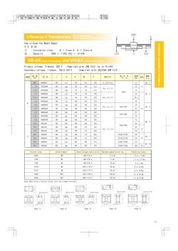
Rack & Panel
MRE Series
Miniature Rectangular / #20 Contacts / .040" Dia. / 7.5 Amps
Receptacle MRE 14S-G
Plug MRE 14P-G
MRE Series plugs and receptacles are the
accepted standard for rectangular-shaped,
miniature, internal-type connectors. They
embody all of the features expected of true
miniaturization: maximum utility of space,
extremely lightweight and unusually high
Hood MRE 14H
working voltage and current ratings. Their
long life and trouble-free service continue to
make them highly popular for use in aircraft,
instrumentation and portable equipment.
The MRE and MRA series share the same
hoods, hardware and accessories.
SPECIFICATIONS
Current Rating:7.5 amps
No. of
Contacts:
7, 8, 9, 11, 14, 18, 20, 21,
26, 34, 41, 42, 50, 75, 104
Pin Contacts: .040 dia., gold plated brass
Socket
Contacts:
Phosphor bronze plated gold.
Termination
Types:
.048 dia. solder cup is
standard. It will accept up to
#20 AWG stranded wire. Pin
and Socket Contacts
available with dip solder
terminations, .025 Dia.
Check Sales Dept. for
lengths available.
Electrical Data:Meets high potential
performance requirements of
MIL-C-28748. Military
versions are QPL’d to
M28748/5 and M28748/6.
The dielectric withstanding
voltage is one minute at 1200
Dielectric:
Polarization:
Hoods:
volts.
Brown mineral filled diallyl
phthalate. Also available in
gray glass filled diallyl
phthalate, per MIL-M-14,
SDG-F.
Gold plated guides provide
positive polarization. Polarized
nickel-plated brass and/or
passivated stainless steel
jackscrews with anodized
aluminum knobs are
available.
Anodized aluminum. May be
applied to either plug or
receptacle. Both top and
side openings are available.
Winchester/Retconn
62 Barnes Industrial Road North, Wallingford, Connecticut 06492 Phone:(203)741-5400 Fax:(203)741-5500 www.winchesterelectronics.com
RP / 34
Rack & Panel
Miniature Rectangular / #20 Contacts / .040" Dia. / 7.5 Amps
MRE Series
TERMINATION TYPES
Solder Cup
Dip Solder
.048 diameter solder cup is the standard
termination for cable and panel mounting
applications. It will accept up to #20 AWG
stranded wire.
For mounting on printed circuit boards, .025
diameter straight dip solder terminations (for
Pin Contacts and Socket Contacts) are
available. Consult the Sales Department for
available lengths.
GUIDE SOCKETS
3 Types of Guide Sockets are Available
Guide
Socket
Application
Actual
Size Photo
Code Letter
G*
The “G” type socket is the standard guide supplied. It
has good physical strength and may be used electrically
in a low current circuit or as a contact for ground leads.
G Type
For General Use
Phosphor
K*
N*
The “K” guide socket is an excellent electrical conductor.
Its extra spring-tension provides a high normal force
uniformily distributed along the surface of the engaged
pilot guide, thus minimizing electrical resistance.
The multivolt drop across extreme ends of the engaged
pilot and socket guide is 10 mv. at 20 amps.
K Type For High
Electrical Conductivity
Beryllium Copper
The high physical strength of the “N” guide socket allows
a greater degree of forcible tightening against a mounting
surface than is permitted by the other guide sockets. This
feature is particularly desirable for mounting connectors
which will be subject to severe vibration in service. “N”
guides are not to be used electrically.
N Type For extra
Mechanical Strength
Brass
Standard Guide
Pin mates with all types
Brass
* For passivated stainless steel add SS suffix
PHYSICAL DATA
HOW TO ORDER: To obtain “K” or “N”
guides in place of the standard “G” type,
substitute the desired socket style code
letter (“K” or “N”) for “G” in both the Plug
and Receptacle Code Numbers.
(See Code Numbers in table at right.
Plug
Total
Winchester
No. of
Contacts Electronics
Code No.
7
8
9
11
14
18
20
21
MRE 7P-G
MRE 8P-N
MRE 9P-G
MRE 11 P-G
MRE14P-G
MRE 18P-G
MRE 20P-G
MRE 21P-G
Recept.
Winchester
Electronics
Code No.
MRE
MRE
MRE
MRE
MRE
MRE
MRE
MRE
7S-G
8S-N
9S-G
11S-G
14S-G
18S-G
20S-G
21S-G
No.
Standard
Contacts,
7.5 Amps
(.048 dia.
solder cup
for #20
AWG)
No.
Standard
Contacts,
10 Amps
(.052 dia.
solder cup
for #18
AWG)
7
8
9
11
14
18
20
21
none
none
none
none
none
none
none
none
Weight
Oz.
Plug Rec.
.3
.2
.3
.3
.3
.4
.5
.5
.3
.2
.3
.3
.3
.4
.4
.5
Plug
Total
Winchester
No. of
Contacts Electronics
Code No.
26
34
41
42
50
75
104
MRE
MRE
MRE
MRE
MRE
MRE
MRE
26P-G
34P-G
41P-G
42P-G
50P-G
75 P-G
104P-JT
Recept.
Winchester
Electronics
Code No.
MRE
MRE
MRE
MRE
MRE
MRE
MRE
26S-G
34S-G
41S-G
42S-G
50S-G
75S-G
104S-G
No.
Standard
Contacts,
7.5 Amps
(.048 dia.
solder cup
for #20
AWG)
26
34
41
42
50
75
104
No.
Standard
Contacts,
10 Amps
(.052 dia.
solder cup
for #18
AWG)
none
none
none
none
none
none
none
Weight
Oz.
Plug Rec.
.6
.8
.8
.9
1.0
1.5
3.3
.5
.7
.6
.8
.9
1.3
2.2
Winchester/Retconn
62 Barnes Industrial Road North, Wallingford, Connecticut 06492 Phone:(203)741-5400 Fax:(203)741-5500 www.winchesterelectronics.com
RP / 35
Rack & Panel
MRE Series
Miniature Rectangular / #20 Contacts / .040" Dia. / 7.5 Amps
OUTLINE
Dimensions are for reference only and
are subject to change. Outline drawings
on request.
.86
.09 R
.37
.27
.78
.37
.27
.37
.075
Typ.
.906
1.219
.13
.172
Typ.
4-40 NC-2 THD.
Receptacle
MRE 7S-G
Slot .038 Wide
Plug
MRE 7P-G
.72
.75
.09 R
.37
.20
.37
.20
.37
.070
Typ.
.750
.562
.09 R
.094
Typ.
4-40 NC-2 THD.
Slot .020 Wide
Note: For MRE8, "G" guides not available
Receptacle
MRE 8S-N
Plug
MRE 8P-N
.86
.37
.27
.78
.37
.37
.27
.075
Typ.
1.313
1.000
.11
.172
Typ.
.09 R
Slot .038 Wide
4-40 NC-2 THD.
Receptacle
MRE 9S-G
Plug
MRE 9P-G
Winchester/Retconn
62 Barnes Industrial Road North, Wallingford, Connecticut 06492 Phone:(203)741-5400 Fax:(203)741-5500 www.winchesterelectronics.com
RP / 36
Rack & Panel
Miniature Rectangular / #20 Contacts / .040" Dia. / 7.5 Amps
MRE Series
OUTLINE
Dimensions are for reference only and
are subject to change. Outline drawings
on request.
.86
.44
.27
.78
.37
.37
.86
.27
.075
Typ.
.56
.09R
.27
.78
.37
.37
.27
.075
Typ.
1.250
1.313
.937
1.000
.06
.09R
.130 Typ.
.13R
Receptacle
MRE 14S-G
4-40 NC-2
THD.
SLOT 0.38 WIDE
.130 Typ.
4-40 NC-2 THD.
.13R
Plug
MRE 14P-G
Receptacle
MRE 18S-N
.37
.86
.44
.09R
.27
.37
Plug
MRE 18P-N
.86
.37
.78
.37
.27
.075
Typ.
.78
.37
.27
SLOT .038 WIDE
.27
.075
Typ.
2.250
1.560
1.937
1.250
.06
.13
.09R
.130 Typ.
4-40 NC-2
THD.
Receptacle
MRE 20S-N
SLOT 0.38 WIDE
.172
SLOT .038 WIDE
4-40 NC-2 THD.
.13R
Plug
MRE 20P-N
Receptacle
MRE 21S-N
Plug
MRE 21P-N
.75
.86
.47
.86
.56
.09R
.27
.78
.37
.37
.075
Typ.
.27
.09R
.23
.27
.78
.37
.37
.27
.075
Typ.
.13
2.000
1.625
1.688
1.312
.06
.13R
.130 Typ.
4-40 NC-2
THD.
Receptacle
MRE 26S-N
SLOT 0.38 WIDE
Plug
MRE 26P-N
MOUNTING
HOLES
FOR NO.4
MACHINE
SCREWS
.180 Typ.
Receptacle
MRE 34S-N
4-40 NC-2 THD.
SLOT .038 WIDE
Plug
MRE 34P-N
Winchester/Retconn
62 Barnes Industrial Road North, Wallingford, Connecticut 06492 Phone:(203)741-5400 Fax:(203)741-5500 www.winchesterelectronics.com
RP / 37
Rack & Panel
Miniature Rectangular / #20 Contacts / .040" Dia. / 7.5 Amps
MRE Series
OUTLINE
Dimensions are for reference only and
are subject to change. Outline drawings
on request.
.44
.075
Typ.
.27
.09R
.75
.47
.23
.78
.37 .27
.86
.37
.09R
.78
.37 .27
.86
.37
.27
.075
Typ.
.06
.16
2.625
2.313
2.312
2.000
.13R
4-40 NC-2
THD.
Plug
.130 Typ.
Receptacle
MRE 41S-N
MOUNTING
HOLES FOR
NO.4 MACHINE
SCREWS
SLOT 0.38 WIDE
.180 Typ.
.88
.075
Typ.
.78
.37 .27
.094 .13
Plug
MRE 42P-G
.86
.27 .37
.75
.47
.23
.86
.27 .37
1.109
.77
.23
SLOT 0.38 WIDE
Receptacle
MRE 42S-G
MRE 41P-N
1.234
4-40 NC-2
THD.
.09
.16R
.13
.78
.37 .27
.075
Typ.
.16
2.594
2.594
2.282 2.719
2.281 2.719
.16R
.16R
.180 Typ.
MOUNTING HOLES FOR
NO.4 MACHINE SCREWS
SLOT 0.38 WIDE
4-40 NC-2
THD.
Receptacle
MRE 75S-N
MOUNTING
HOLES
FOR NO.4
MACHINE SCREWS
4-40 NC-2
THD.
.180 Typ.
Receptacle
MRE 50S-N
Plug
MRE 75P-N
SLOT 0.38 WIDE
Plug
MRE 50P-N
1.531
.37
.44
.16
.37
.27
.37
.37
.27
6-32 UNC
2A THD
.075
Typ.
2.375
.27
.44
.075
Typ.
8-32
UNC
2A THD
.78
.86
.78
1.359
.88
.781 1.094
2.750
.13R
MOUNTING
HOLES
FOR NO.4
MACHINE
SCREWS
.180 Typ.
.09R
.130 Typ.
062 DIA HOLE
FOR SAFETY WIRE
Receptacle
MRE 104S-JT
Plug
MRE 104P-J
4-40 NC-2
THD.
Receptacle
MRE 11S-G
SLOT 0.38 WIDE
Plug
MRE 11P-G
Winchester/Retconn
62 Barnes Industrial Road North, Wallingford, Connecticut 06492 Phone:(203)741-5400 Fax:(203)741-5500 www.winchesterelectronics.com
RP / 38
Rack & Panel
MRE Series
Miniature Rectangular / #20 Contacts / .040" Dia. / 7.5 Amps
JACKSCREWS & JACKSOCKETS
Polarized jackscrews give the ease and
assurance of threaded positive coupling. The
actuating side consists of two turnable screws,
one male and one female, each with knurled and
slotted knobs. On the mating half are the two
fixed screws required to complete the locking
action. When mated, the jackscrews may be
locked with a safety wire through the hole in the
self-locking pin (in the jackscrew shaft).
4-40 NC-2 THD.
EXCEPT SIZE 104
WHICH IS 6-32 NC 2
.78
.98 For
Size 104
The drawings show the extension of the jackscrew
knobs beyond a typical MRA connector and
beyond the connector-and-hood assembly (center
drawings). Dimensions given are constant for all
connectors except as noted. Other dimensions
applicable to various hood styles are detailed in
the chart.
.16
A
MONO
JACKSCREW
B
6-32 UNC 2 THREAD
EXCEPT SIZE 104
WHICH IS 8-32 UNC 2
JACKSOCKET
AND
OR
OR
JACKSCREW
.16
C
HOOD
Connector with fixed
Jackscrews.
Code designation: J
SELF LOCKING PIN
MONO
JACKSOCKET
052 DIA SAFETY WIRE HOLE
E
E
D
Mating connector half
with turnable Jackscrews-with-Knobs.
Code designation: JT
Mating connector half with Hood
and turnable Long Jackscrewswith Knobs. Code designation:
JTCH, JTCH1
Mating connector half
with Hood and
turnable Monojacks.
Code designation:
JTDH, JTDH1
DIMENSIONS
Dimensions are for reference only and
are subject to change. Outline drawings
on request.
Connec- Dimension A
tor Size H H1 H8 H9
Dimension E
Dimension B Dimen Dimen
C
H H1 H8 H9
D
H H1 H8 H9
MRE 7
MRE 8
MRE 9
MRE 14
MRE 18
MRE 20
MRE 21
MRE 26
MRE 34
MRE 41
MRE 42
MRE 50
MRE 75
MRE 104
–
–
–
–
–
–
–
–
.63
–
.58
.58
.56
.5
–
–
–
–
–
–
.67
.81
.63
.63
.58
.58
.56
.67
.58
.5
.59
.59
.59
.59
.59
.59
.63
.63
.58
.58
.56
–
.58
.5
.58
.58
.83
.58
.67
.59
.63
–
.58
.58
.56
–
–
.5
.59
.59
.59
.59
.59
.59
.63
–
.58
.58
.56
.67
–
–
–
–
–
–
–
–
.63
–
.58
.58
.56
–
–
–
–
–
–
–
–
–
.63
–
.58
.58
.56
–
–
–
–
–
–
–
–
–
.63
–
.58
.58
.56
.5
.80
.80
.80
.80
.80
.80
.80
.80
.80
.80
.80
.80
.80
.80
1.31
1.31
1.31
1.31
1.31
1.31
1.31
1.31
1.31
1.31
1.31
1.31
1.31
1.52
–
–
–
–
–
–
2.09
2.61
2.41
2.41
2.41
2.41
2.41
3.42
2.09
2.02
2.41
2.41
2.41
2.41
2.41
2.41
2.41
2.41
2.41
2.41
2.41
–
2.09
2.02
2.09
1.84
2.09
1.84
2.09
2.41
2.41
–
2.41
2.41
2.41
–
–
2.02
2.41
2.41
2.41
2.41
2.41
2.41
2.41
–
2.41
2.41
2.41
3.42
Dimension F
H H1 H8 H9
–
–
–
–
–
–
–
–
2.41
–
2.41
2.41
2.41
3.25
–
–
–
–
–
–
–
–
2.41
–
2.41
2.41
2.41
–
–
–
–
–
–
–
–
–
2.41
–
2.41
2.41
2.41
–
–
–
–
–
–
–
–
–
2.41
–
2.41
2.41
2.41
3.25
New Monojacks Assemble and Disassemble With Remarkable Ease and Speed
To free the connector from the hood simply
remove four screws. Monojacks may be used
on miniature rectangular connectors with from
MOLDINGS HAVE STRAIGHT THRU HOLES
34 to 104 contacts. Molds have 2 center thru
holes and 4 mounting holes.
MONOJACKS ARE CAPTIVATED IN KEYHOLE
SLOT OF HOOD AS SHOWN ABOVE.
WHEN USING SHELLS, MONOJACKS ARE
CAPTIVATED IN KEYHOLE OF SHELL AND
CLEARANCE HOLES ARE PLACED IN HOODS.
Winchester/Retconn
62 Barnes Industrial Road North, Wallingford, Connecticut 06492 Phone:(203)741-5400 Fax:(203)741-5500 www.winchesterelectronics.com
RP / 39
Rack & Panel
Miniature Rectangular / #20 Contacts / .040" Dia. / 7.5 Amps
MRE Series
OUTLINE
JACKSCREWS & JACKSOCKETS
.22
.50
.19 DIA
.22 DIA.
DIA.
.078 INT. HEX.
.25 HEX.
A
A
A
A
JTCW
JTCU
JTCX
JTCZ
.22 DIA.
.22
DIA.
.078 INT. HEX.
1"
.36
Dimensions are for reference
only and are subject to change.
Outline drawings on request.
JTW
JTU
.25 HEX.
6-32 UNC 2 THD.
(TYP.)
.78
.80 TYP.
6-32 UNC 2 THD. (TYP.)
.16 TYP.
JZ
JTX
DIMENSIONS
All jackscrews and sockets are stainless steel, passivated,
except for J & JTD which are nickel-plated brass. All knobs
are aluminum, anodized except JTW and JTCW which are
stainless steel, passivated.
Hood Type
Size
7
9
14
18
20
21
26
34
41
42
50
75
Type JTCW
H
H1
H8
Dimension A
– 1.91 1.91
– 2.22 1.91
– 2.22 1.66
– 2.22 1.66
– 2.22 1.66
1.91 2.22 1.91
2.22 2.22 2.22
2.22 2.22 2.22
2.22 2.22
–
2.22 2.22 2.22
2.22 2.22 2.22
2.22 2.22 2.22
H9
–
2.22
2.22
2.22
2.22
2.22
2.22
2.22
–
2.22
2.22
2.22
Type JTCU
Size
7
9
14
18
20
21
26
34
41
42
50
75
H
H1
H8
Dimension A
– 2.16 2.16
– 2.47 2.16
– 2.47 1.91
– 2.47 1.91
– 2.47 1.91
2.16 2.47 2.16
2.47 2.47 2.47
2.47 2.47 2.47
2.47 2.47
–
2.47 2.47 2.47
2.47 2.47 2.47
2.47 2.47 2.47
H9
–
2.47
2.47
2.47
2.47
2.47
2.47
2.47
–
2.47
2.47
2.47
Size
7
9
14
18
20
21
26
34
41
42
50
75
Type JTCX
H
H1
H8
Dimension A
– 2.03 2.03
– 2.34 2.03
– 2.34 1.78
– 2.34 2.03
– 2.34 1.78
2.03 2.34 2.03
2.61 2.34 2.34
2.34 2.34 2.34
2.34 2.34
–
2.34 2.34 2.34
2.34 2.34 2.34
2.34 2.34 2.34
H9
–
2.34
2.34
2.34
2.34
2.34
2.34
2.34
–
2.34
2.34
2.34
Size
7
9
14
18
20
21
26
34
41
42
50
75
Type JTCZ
H
H8
H9
Dimension A
– 2.16 2.16
– 2.47 2.16
– 2.47 1.91
– 2.47 2.16
– 2.47 1.91
2.16 2.47 2.16
2.77 2.47 2.47
2.47 2.47 2.47
2.47 2.47
–
2.47 2.47 2.47
2.47 2.47 2.47
2.47 2.47 2.47
H1
–
2.47
2.47
2.47
2.47
2.47
2.47
2.47
–
2.47
2.47
2.47
Winchester/Retconn
62 Barnes Industrial Road North, Wallingford, Connecticut 06492 Phone:(203)741-5400 Fax:(203)741-5500 www.winchesterelectronics.com
RP / 40
Rack & Panel
Miniature Rectangular / #20 Contacts / .040" Dia. / 7.5 Amps
MRE Series
OUTLINE
HOODS - FORMED ALUMINUM
Dimensions are for reference only and
are subject to change. Outline drawings
on request.
DIMENSIONS
Top Cable Opening
Code No.
Dimensions
A
MRE 7H*
MRE 7H-8
MRE 8H*
MRE 8H-8
MRE 9H*
MRE 9H-8
MRE 14H*
MRE 14H-8
MRE 18H*
MRE 18H-8
MRE 20H*
MRE 20H-8
MRE 21H
MRE 21H-8
MRE 26H
MRE 26H-8
MRE 34H
MRE 34H-8
MRE 41H
MRE 42H
MRE 42H-8
MRE 50H
MRE 50H-8
MRE 75H
MRE 75H-8
MRA104H
Side Cable Opening
B
C
D
Cable
Opening Wt.
E
F G Oz.
.28
1 1.31 1.22 .44 .31D –
.3
.28
1 1.30 1.22 .44 .59 .31 .3
.28
1 1.31 .81 .44 .25D –
.2
.28
1 1.30 .81 .44 .31D –
.2
.28
1 1.31 1.31 .44 .31D –
.3
.28
1 1.30 1.31 .44 .59 .31 .3
.28 .75 1.19 1.25 .5 .44D –
.3
.28 .75 1.05 1.25 .5 .59 .38 .3
.28 .75 1.19 1.31 .63 .44D –
.4
.28 .75 1.25 1.31 .63 .63 .44 .4
.25 .75 1.19 1.56 .5 .44D –
.3
.25 .75 1.05 1.56 .5 .66 .38 .3
.28 .91 1.34 2.25 .44 .59 .31 .5
.28 .91 1.36 2.25 .44 .78 .31 .5
.28 1.28 1.72 1.63 .64 .59 .38 .4
.28 1.28 1.78 1.63 .64 .78 .44 .4
.28 1.25 1.69 2
.83 .66D –
.6
.28 1.25 1.75 2
.83 1.06 .56 .6
.28 1.25 1.69 2.63 .5 .66 .44 .6
.09 1.30 1.73 2.31 .83 .63D –
.7
.09 1.30 1.80 2.31 .83 1.06 .56 .7
.09 1.30 1.73 2.59 .83 .63D –
.8
.09 1.30 1.80 2.59 .83 1.06 .56 1.8
.09 1.31 1.75 2.59 1.19 .63 .88 1.0
.09 1.31 1.86 2.59 1.19 1
.88 1.0
FOR DIMENSIONS SEE PAGE RP/ 36
Fits
Connector
Code No.
MRE 7 (P or S)
MRE 7 (P or S)
MRE 8 (P or S)
MRE 8 (P or S)
MRE 9 (P or S)
MRE 9 (P or S)
MRE 14 (P or S)
MRE 14 (P or S)
MRE 18 (P or S)
MRE 18 (P or S)
MRE 20 (P or S)
MRE 20 (P or S)
MRE 21 (P or S)
MRE 21 (P or S)
MRE 26 (P or S)
MRE 26 (P or S)
MRE 34 (P or S)
MRE 34 (P or S)
MRE 41 (P or S)
MRE 42 (P or S)
MRE 42 (P or S)
MRE 50 (P or S)
MRE 50 (P or S)
MRE 75 (P or S)
MRE 75 (P or S)
MRE 7H-1
MRE 8H-1
MRE 8H-9
MRE 9H-1
MRE 9H-9
MRE 14H-1
MRE 14H-9
MRE 18H-1
MRE 18H-9
MRE 20H-1
MRE 20H-9
MRE 21H-1
MRE 21H-9
MRE 26H-1
MRE 26H-9
MRE 34H-1
MRE 34H-9
MRE 41H-1
MRE 42H-1
MRE 42H-9
MRE 50H-1
MRE 50H-9
MRE 75H-1
MRE 75H-9
MRA104H-9
Dimensions
A
B
C
D
Cable
Opening Wt.
E
F G Oz.
.28 1.28 1.53 1.22 .44 .31D –
.3
.28 1.28 1.13 .81 .44 .25
–
.2
.28 1.28 1.13 .81 .44 .59 .31 .2
.28 1.28 1.63 1.31 .44 .31D –
.3
.28 1.28 1.61 1.31 .44 .59 .31 .3
.28 1.28 1.69 1.25 .5 .38D –
.3
.28 1.28 1.55 1.25 .5 .59 .38 .3
.28 1.28 1.75 1.31 .63 .44D –
.3
.28 1.28 1.81 1.31 .63 .69 .44 .3
.28 1.28 2 1.56 .5 .38D –
.3
.28 1.28 1.86 1.56 .5 .66 .38 .3
.28 1.28 2.69 2.25 .44 .53 .25 .5
.28 1.28 2.72 2.25 .44 .78 .31 .5
.28 1.28 2.06 1.63 .64 .59 .38 .4
.28 1.28 2.13 1.63 .64 .78 .44 .4
.28 1.25 2.42 2
.83 .66D –
.6
.28 1.25 –
2
.83 .81 .56 .6
.28 1.25 3.06 2.63 .5 .66 .44 .6
.09 1.30 2.73 2.31 .83 .63 .5
.7
.09 1.30 – 2.31 .83 .84 .56 .7
.09 1.30 3.02 2.59 .83 .63 .5
.8
.09 1.30 – 2.59 .83 1.06 .56 .8
.09 1.31 3.02 2.59 1.19 .63 .88 1.0
.09 1.31 – 2.59 1.19 1
.88 1.0
FOR DIMENSIONS SEE PAGE RP/36
Fits
Connector
MRE 7 (P or S)
MRE 8 (P or S)
MRE 8 (P or S)
MRE 9 (P or S)
MRE 9 (P or S)
MRE 14 (P or S)
MRE 14 (P or S)
MRE 18 (P or S)
MRE 18 (P or S)
MRE 20 (P or S)
MRE 20 (P or S)
MRE 21 (P or S)
MRE 21 (P or S)
MRE 26 (P or S)
MRE 26 (P or S)
MRE 34 (P or S)
MRE 34 (P or S)
MRE 41 (P or S)
MRE 42 (P or S)
MRE 42 (P or S)
MRE 50 (P or S)
MRE 50 (P or S)
MRE 75 (P or S)
MRE 75 (P or S)
* H Hoods for MRE 7, 8, 9, 14, 18 and 20 will not accept JTC
hardware. Use H8 hoods.
Winchester/Retconn
62 Barnes Industrial Road North, Wallingford, Connecticut 06492 Phone:(203)741-5400 Fax:(203)741-5500 www.winchesterelectronics.com
RP / 41
Rack & Panel
Miniature Rectangular / #20 Contacts / .040" Dia. / 7.5 Amps
MRE Series
Lock Tabs (MRE-V shown)
HOODS - LOCKING
Lever & Pivot Assemblies (MRE-VL shown)
Vibration Locks*
Vibration locks offer simplicity of design and
positive locking in excess of 50G shock impact
and 10G vibration acceleration. Mating halves
automatically lock when engaged. To unlock,
MRA 9, 14, 20, depress the levers. Drilled holes in the levers
are provided for safety wiring. Vibration
locks are available separately for assembly
on connectors now in service. Each code
number indicates two units: two levers with
two pivots, and two lock tabs.
34, 41, 42, 66
*US Patent Number 2760174
Lever
Used on
Lock Tabs
& Pilot (See Note) Connectors
Assembly
MRE-VL
MRE-VL2
MRE-V
MRE-V2
MRE 50,75
Note: When panel mounting the lock-tab half of a MRE 34, MRE 42 or MRE 50 and MRE 66 connector, flat washers
(.033 minimum thickness) should be used on the mounting screws to shim the molding away from the panel.
DIMENSIONS / OUTLINE
MOUNTING BRACKETS
H
Code No.
A
B
C
DIMENSIONS
D E F G
Wt.
Oz.
H
.128 Dia 3 Holes
MRE 50B 1.06 .688 3.031 3.44 .13 .28 .78 (No. 4 Mounting
Screw)
.4
.150 Dia 3 Holes
MRE 75B 1.48 1.047 3.062 3.56 .14 .30 1.14 (No. 6 Mounting
Screw)
.6
F
A
B
G
E
C
2.625
D
Panel
Opening
MRE 50 and MRE 75 connectors use
the standard MRE 50 and MRE 75
mounting brackets
.11R
DIMENSIONS / OUTLINE
PRE-SHAPED NYLON
POTTING FORMS
Dimensions are for reference only and
are subject to change. Outline drawings
on request.
Potting Form
Code No.
MRE 7 FM
MRE 8 FM
MRE 9 FM
MRE 14 FM
MRE 18 FM
MRE 20 FM
MRE 21 FM
MRE 26 FM
MRE 34 FM
MRE 41 FM
MRE 42 FM
MRE 50 FM
MRE 75 FM
Fig.
3
2
3
2
2
2
3
2
1
2
1
1
1
the connector after potting. Because of
floating contacts, connector halves should
always be engaged during the potting
operation to preserve contact alignment.
Each form matches the back opening contour
of its appropriate shell, and stays easily in
place during the potting operation. Of
negligible weight, it need not be removed from
Dimensions
A
B
.62
.46
.77
.93
.87
1.12
1.68
1.18
1.38
2.18
1.69
1.97
1.98
.43
.43
.43
.49
.61
.49
.43
.61
.80
.49
.80
.80
1.16
Winchester/Retconn
A
A
A
B
B
B
.50 .63
Figure 1
.50 .63
.50 .63
Figure 2
Figure 3
62 Barnes Industrial Road North, Wallingford, Connecticut 06492 Phone:(203)741-5400 Fax:(203)741-5500 www.winchesterelectronics.com
RP / 42
Rack & Panel
Miniature Rectangular / #20 Contacts / .040" Dia. / 7.5 Amps
MRE Series
ORDERING INFORMATION
Omit steps not required
MRE
■ Step 1
■ Step 2
Insert Series
Code:
MRE
By adding “ML”
to the series
code, connector
is supplied with
diallyl phthalate
type SDG-F
and mil plated
contacts.
Example: MREML
Number of
Contacts:
7, 8, 9, 11,
14, 18, 20,
21, 26, 34,
41, 42, 50,
75, 104
■ Step 3
Contact
Designation:
P - Pin
S - Socket
When
ordering
molding less
hardware to
be used with
mono-jacks,
see note
below.
34
■ Step 4
Type of
Contact:
Blank =
Standard
Solder Cup
Straight
Dip Solder
.025" dia.:
D3 = .094"
D4 = .125"
D5 = .156"
For additional
lengths in 1/32"
increments,
contact
Winchester’s
Sales
Department.
■ Step 5
Guides and
Jackscrew
Locks:
(See bottom
Chart)
H
G
S
VL
■ Step 6
■ Step 7
■ Step 8
Hoods:
Vibration
Accessories:
H - Standard Locks:
FM - Potting
Top
V - Lock Tab
Forms.
Opening* V2 - Lock Tab
Cannot be
Used with
H1 - Standard
(Size 50
Hoods.
Side
& 75)
Request
Opening
VL - Lever & Pivot
availability
H8 - Large Top
Ass’y
informaOpening
VL2 - Lever & Pivot
tion.
H9 - Large Side
Ass’y (Size
Opening
50 & 75)
*For MRE 7, 8,
9, 14, 18 and 20,
JTC hardware
may not be used
with H hoods.
Use H8 hoods.
■ Step 9
Special
Options:
Consult Sales
Department
■ Step 5
Guides
*G
Phosphor Bronze Cylindrical Guides*
*K
Beryllium Copper Cylindrical Guides
*N
Brass Cylindrical Guides*
Guides are not recommended for Size 104
“P” indicates two guide pins or two jackscrews
(Ex. JTCP)
“S” indicates two guide sockets or two jacksockets.
(Ex. GS)
Jackscrew Locks
***J
Polarized Fixed Jackscrew and Jacksocket
JT
Polarized Short Turning Jackscrew
and Jacksocket
JTC
Polarized Long Turning Jackscrew
and Jacksocket
Polarized Long Turning Mono-Jackscrew and
*** JTD
Mono-Jacksocket for Sizes 34, 42, 50, 75,
and 104 only.
** JZ
** JTW
** JTU
** JTX
** JTCW
** JTCU
** JTCX
Same as J but with 6-32 mtg. thd. (Not
available 5-3, 8) (Std. on 104)
Same as JT but with knurled round knob
with internal hex (not avail. 5-3, 8, 104)
Same as JT but with knurled round knob
with screwdriver slot (not avail. 5-3, 8, 104)
Same as JT but with hex knob (not avail. 53, 8, 104)
Same as JTC but with knurled round knob
with internal hex (not avail. 5-3, 8, 104)
Same as JTC but with knurled round knob
with screwdriver slot (not avail. 5-3, 8, 104)
Same as JTC but with hex knob (not avail.
5-3, 8, 104)
Same as JTC but with prybar knob.
** JTCZ
** Request availablity information.
*** Material: Nickel-plated brass - standard
Example: MRE34SJTDBH8
* For passivated stainless steel add SS suffix (Example: MRE34SGSS)
Mounting Note: Connectors MRE 41, MRE 26, and smaller use guides for mounting in a hood or on a panel.
Connectors MRE 34, MRE 42, MRE 50, MRE 75, use four #4 machine screws, in addition to guides, for
mounting in a hood or on a panel.
Note:
When ordering hoods, hardware and connectors separately for use with JTD Monojacks, connectors must be ordered as follows:
Pin connector = MRE34P8, MRE42P8, etc.
Socket connector = MRE34S8, MRE42S8, etc.
The number “8” indicates special housing for use with the JTD Monojack hardware
(available on sizes 34, 42, 50, 66, 75 and 104).
Winchester/Retconn
62 Barnes Industrial Road North, Wallingford, Connecticut 06492 Phone:(203)741-5400 Fax:(203)741-5500 www.winchesterelectronics.com
RP / 43
© Copyright 2026 ExpyDoc