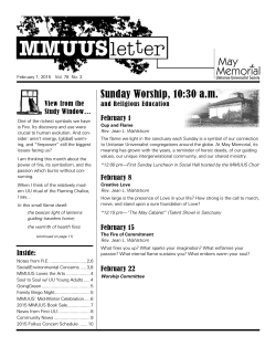
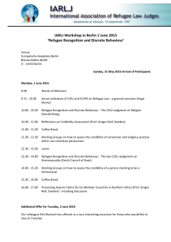
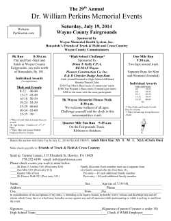
Memorial Union Renewal Detailed Project Program University of California Davis Project #9521200 Design and Construction Management Memorial Union Renewal Detailed Project Program University of California Davis UC Davis Memorial Union Renewal Detailed Project Program TABLE OF CONTENTS 1.0 ACKNOWLEDGEMENTS EXECUTIVE SUMMARY 1.1 Executive Summary 1.2 Neighboring Projects 2.0 PROJECT GOALS 2.1 3.0 PROGRAM (INCLUDING SITE) 3.1 3.2 3.3 4.0 SUSTAINABLE DESIGN 4.1 4.2 5.0 ROOM DATA 6.0 5.1 5.2 Project Goals Program Process Evolution of the Memorial Union Program Sustainable Goals Sustainable Criteria Room Data Spreadsheet Detailed Space Requirement Diagrams BUILDING SYSTEMS 6.1 6.2 6.3 6.4 6.5 6.6 6.7 6.8 6.9 Site Utilities Vertical Transportation Fire Sprinkler Plumbing Systems HVAC Systems HVAC Controls Systems Electrical Systems Telecommunication System Fire Alarm System 7.0 COST 7.1 Cost Summary UC Davis Memorial Union Renewal Detailed Project Program TABLE OF CONTENTS 8.0 9.0 SCHEDULE 8.1 8.2 Delivery Method Schedule CODE ANALYSIS 9.1 9.2 9.3 9.4 9.5 9.6 Applicable Laws, Codes, Rules, Regulations, Ordinances, and Standards Reviewing Agencies Building Data Exiting Requirements Restroom count Fire Life Safety 10.0 APPENDIX 10.1 10.2 Building Accessibility Survey Memorial Union Fire Life Safety Upgrades UC Davis Memorial Union Renewal Detailed Project Program 1.0 EXECUTIVE SUMMARY 1.1 Executive Summary Memorial Union north courtyard The purpose of this program is to establish the goals and direction for the Memorial Union renewal project with enough detail to provide a conceptual design, schedule, and cost estimate. The Memorial Union (MU), built in 1955 and located on the University of California, Davis campus, houses three primarily different functions: a one story student-run dining facility called the COHO, a two story campus bookstore, and a five story tower for student services related to the Associated Students of University of California, Davis (ASUCD). The proposed project will consist of a remodel of the bookstore (31,200 gross square feet), a remodel of the first two stories of the student services tower (32,300 gross square feet), and a remodel of the adjacent north and south courtyards (56,640 gross square feet). The project will be spilt into two parts. Phase one will include the bookstore remodel and phase two will encompass the student services tower and site work. The goals for this project include improving student services, reestablishing the Memorial Union as the front door to the core campus, and emphasizing the importance of the memorial within the building. The total construction budget for this project is $13,050,000 considering a construction bid date of the early 2014. The proposed schedule anticipates preliminary design phase starting February 2013 and the working drawings starting September 2013. Construction of phase one will start February of 2014 and Phase two will start June 2014. 1.2 Neighboring projects Due to the close proximity to this project, it is worth noting that several other improvements are being made to the Memorial Union complex and its surroundings and will be occurring separate but concurrent with this project. The following diagram illustrates their scope. UC Davis Memorial Union Renewal Detailed Project Program 1.0 EXECUTIVE SUMMARY • Memorial Union/Unitrans Terminal Improvements This project will expand and the existing bus terminal north of the Memorial Union. Improvement will include redirecting traffic, improving safety for pedestrians and increasing terminal capacity, providing a pedestrian plaza that will connect to the north courtyard of the Memorial Union. • Freeborn Hall Seismic Improvements This Project will provide structural and accessibility improvements to the existing auditorium building which its entrance shares with the north courtyard of the Memorial Union. • Howard Way Corridor Master Plan This project begins at the intersection of Howard Way and Russell Blvd. and terminates at the north courtyard of the Memorial Union. A master plan will provide design guidelines for the corridor including the MU terminal Project and the North courtyard of the MU so that a cohesive identity will exist along the entire approach to the Memorial Union for pedestrians and vehicles. UNITRANS TERMINAL 3/14 - 8/14 MU RENEWAL 1/14 - 7/15 NOTE: DATES REPRESENT CONSTRUCTION DURATION SITE PLAN - MEMORIAL UNION DISTRICT FUTURE PROJECTS UC Davis Memorial Union Renewal Detailed Project Program 2.0 GOALS 2.1 Project Goals The goals for this project are based on the 2007 Student Union Master Plan which established a framework for renovation and development to meet the evolving needs of the union. These goals drive the solutions developed in the program. 1. Make the MU a more vibrant environment / destination The MU will become a destination for students that promotes social gathering and provides a variety of options for collaborative interaction in positive uplifting environment. 2. Maintain the MU as an historic icon The MU will recapture its importance as the historic heart of the campus. 3. Create an appropriate “entry” to the complex The MU is the front door to the core campus and its architecture should reflect this prominence. This entry should improve access, visibility, and sense of place. 4. Create strong connections to the central quad and surrounding student centers 5. Improved way finding and circulation (both interior & exterior) The MU will align with existing campus organizing principles. Circulation as one approaches and moves through the building will be guided by landmarks such the Centennial Axis. Circulation within the building will be open and clear. 6. North & South plaza improvements The north plaza will become a destination by promoting social activity through a softer landscape and break‐out spaces integrated into the environment. UC Davis Memorial Union Renewal Detailed Project Program 2.0 GOALS 7. Improve outdated building systems, finishes, fixtures Provide access to state of the art technology and modern durable finishes to establish the open gathering areas as a showcase for the campus. 8. Improve opportunity for UCD Stores and ASUCD venues Increase visibility and access to retail spaces and other student services. Eliminate redundancy of services. 9. Create indoor/outdoor connections Provide a more transparent and porous perimeter to promote a stronger connection between indoor and outdoor space . 10. Create flexibility within spaces Provide large open interior spaces that allow that allow easy reconfiguration of furniture so that social spaces can be customized to individual needs. 11. Coordinate MU Renewal with Northern entry to campus A separate but concurrent project is developing a master plan for the Howard Way corridor and intersection at Russell Blvd. which is located immediately north of the MU. The intent of this plan is to create a cohesive look to the entire MU corridor` and provide a new gateway to the campus. These design guidelines will apply to the north courtyard of the MU as well. UC Davis Memorial Union Renewal Detailed Project Program 3.0 PROGRAM 3.1 Program Process A series of workshops were held with representatives of Campus Recreation and Unions to analyze and understand the goals for the project and then apply this knowledge to develop the solutions outlined in the program. The process began with overarching concepts applied to the entire MU complex and then refined to apply to specific spaces. 3.2 Evolution of the Memorial Union‐ The Challenges Campus gateway circa 1920’s The intersection of the Howard Way and Russell Boulevard, just north of the current Memorial Union complex, has acted as the gateway to the campus since the 1920’s. Howard Way is the starting point of an axis that accentuates the center of the core campus continuing through the campus quad and terminating at the historic campus Library. A student‐built trellis structure that flanked either side of Howard Way was the physical gateway to the campus and the original memorial to fallen student‐soldiers of World War One. When the Memorial Union was built in the 1955 the memorial became a part of the building and was expanded to include student‐soldiers of the Second World War. The Memorial Union became the true front door to the campus in a symbolic and physical sense. As the MU has aged, other more contemporary union‐like buildings have been built at different locations on campus. For example, the ARC and Student Community Center are designed to accommodate students’ technological and social needs and have become very popular destinations. These buildings offer services and gathering opportunities as does the MU, but in a more open‐ social environment conducive to collaborative study which is more compatible with today’s curriculum. The decentralization of student service buildings has further diminished the MU’s iconic status as the front door to the campus. As the campus has grown, distinct districts have developed on campus such as the performing arts district to the south of campus which has its own high profile campus entry immediately off the adjacent Highway 80. UC Davis Memorial Union Renewal Detailed Project Program 3.0 PROGRAM While attempts have been made to keep the building current with students needs through remodel projects in the last 25 years, the result has led to redundant spaces and difficult way‐ finding within the building. The predominant area for student gathering on the first two floors of the building is divided into several lounge style rooms which discourage social interaction and are typically underutilized. 3.3 Program The program for the Memorial Union Renewal predominantly addresses the public spaces of the first two floors of the existing building and the surrounding site. Diagrams following this section further illustrate the concepts described below. North courtyard circa 1960’s Building Approach‐ Memorial Union The Memorial Union is an historic icon that acts as a front door the campus. The building’s architecture should convey this importance as well as act a beacon that clearly indicates where to enter. Circulation to the building can be aligned with existing campus axes to promote clear way‐finding. For example, the Centennial Axis originates at the southern edge of the quad, at the historic entry to Shields Library and runs north bisecting the quad and passes through the Memorial Union and ultimately terminates at the intersection of Howard Way and Russell Blvd. The front door of the Memorial Union and to the campus will align with this axis. A two story atrium space will be added to the north elevation of the Memorial Union building to emphasize this alignment and create a prominent entry that acts as a beacon to individuals approaching the building from the north and west. Building Approach‐ Bookstore In order to increase opportunities and visibility for the bookstore, the approach to the building will be rethought on its east and west side. The bookstore acts as a border along the east side of the north MU courtyard and sits opposite the Freeborn Hall which borders the west. The existing main entry to Freeborn hall and the new book entry on the opposite side create a secondary axis which intersects with the Centennial Axis running from north to south. This intersection occurs at the center of the north MU courtyard which becomes a nexus for increased activity within this outdoor space. UC Davis Memorial Union Renewal Detailed Project Program First floor interior circa 1960’s 3.0 PROGRAM The new east entry to the bookstore is also positioned to increase visibility. The entry will be located on south east corner of the building to capitalize on the pedestrian traffic approaching the MU from the east and from bike traffic traveling north and south along East Quad Avenue. The existing interior main entry to the bookstore will be eliminated. Building Interior‐ Memorial Union The primary desire for the interiors of this project is to provide large open feeling social areas with clear way finding. This will be done by providing new space, simplifying circulation, and reducing the number of divisions within the building. The front door to the Memorial Union is part of a new two story 2,400 s.f. atrium on the north face of building. This space will be open to the second floor, providing a showcase for student activity on both levels. It is also the point where the centennial axis intersects with east‐west circulation moving through the building. All existing partition walls in the adjacent student area will be removed to create an open floor plan for student gathering. A variety of seating opportunities will be arranged in different formats on this level to allow for individual and group use. This will include groupings of soft seating and low tables, normal height chairs and tables, and a variety of individual seating opportunities. The south wall along the gathering space will have multiple points of egress to allow for a filtering into the indoor‐outdoor space of the south MU courtyard. Guest services will be centrally located on the first floor to promote clear way‐finding. All destination points will be visible from this location. Retail opportunities along the east wing of the building will be consolidated and organized along a single loaded corridor that provides additional social gathering opportunities. The retail storefronts along this corridor will have large openings that promote a fluid feeling between to the two zones. The retail spaces will include: North retail space (350 s.f.): managed by Associated Students Main retail space (1,100 s.f.): managed by Associated Students Convenience store (2,000 s.f.): collaboration between COHO and Campus Stores UC Davis Memorial Union Renewal Detailed Project Program 3.0 PROGRAM Bookstore Grill (2,200s.f): managed by Associated Students with food service provided by the COHO. This space will serve pub style food and double as an entertainment venue that can accommodate approximately 70 people. The second floor of the Memorial Union will have a similar function as the first. The floor plan will be open and provide a variety of social gathering opportunities and breakout space which will be further enhanced by relocating the fireplace, from the first floor, to the south wall of this level. The functions of the MU station (the computer lab formerly located on the first level) will be dispersed among second floor. The southeast corner will be dedicated to a manned printing station that will serve a minimum of 32 computers. Building Interior‐Bookstore The bookstore will receive focused improvements related to adjusting the floor layout to accommodate the new store entries and the relocation of administrative staff. A multiple point‐of‐scale location will be located at the new south east entry and the single point‐of‐sale location will reside at the new west entry. The existing freight elevator that serves the basement and first floor will be replaced by one that serves as the main elevator for the entire store including the second floor mezzanine. Administrative staff at the north east corner of the first floor and in the second floor mezzanine will be relocated to the MU tower as a separate project. The vacated first floor space will become additional retail display and the second floor space will become back stock storage. The computer sales and repair department, called the Tech Hub, will be relocated to the approx. 1,000 s.f. space formerly occupied by the MU station (computer lab). The resulting vacated space will also become additional retail display for the bookstore. The basement will remain primarily for textbook sales. The billiards room immediately south of textbook sales will become a flex space for the bookstore and serve as additional storage and a point‐of‐sale location depending on seasonal needs. UC Davis Memorial Union Renewal Detailed Project Program 3.0 PROGRAM A new sale fixtures and furnishing layout will accommodate these changes to the plan. (This layout will be provided by a third party consultant and it is not a part of this project). The Memorial It is the intent of this project to make the memorial a more prominent feature that properly honors the individuals for whom it is dedicated. The current memorial to the fallen student soldiers of the campus is a book where each page has a photograph and biography of a soldier. This book is kept open to a different page each week in a glass display case located in the corner of a study lounge. Memorial fire place circa 1960’s The new memorial is to incorporate and preserve the original book, but make it a more prominent and accessible feature of the building. The memorial is to be located in the new two story atrium in such a way that it is a recognizable landmark from the interior and exterior of the building. This feature will have an interactive multimedia component that allows individuals to browse the contents of the entire book and possibly learn about the history of the building itself. Collaboration between the design team and the student community is a preferred route for developing the design for the memorial. Site The existing north MU and south MU courtyards are similar in that both are bordered by buildings on three of their four sides, but they a have distinctly different feel. The north courtyard has a cold hard feel that must be softened and made more welcoming so that it complements the building as the front door to the campus. The south courtyard benefits from some existing landscape that makes the space more inviting, but it needs a stronger connection to the interior social spaces. The circulation through the north courtyard will acknowledge the primary and secondary axes described previously. Raised planters with integrated seating will provide break out opportunities for individuals and groups. The raise planter concept also provides a solution for the southern half of the courtyard which was previously unplantable because of the basement space below. UC Davis Memorial Union Renewal Detailed Project Program 3.0 PROGRAM The existing canopies structures at the various building entries will be replaced with ones that are more consistent with the architecture of the building. The south courtyard is a vital space that benefits from the activity of the Memorial Union, the COHO and the adjacent Quad. The south wall of the MU is intentionally porous to allow a blending of the indoor and outdoor space. This courtyard will have integrated planters and outdoor furnishings to give it a feel of an outdoor living room South courtyard circa 1950’s The Memorial Union is a campus destination that is central to the social and academic needs of the students. While the project will not substantially increase the footprint of the building, the proposed modifications will revitalize its physical and symbolic importance to the campus. C A M P U S A R R I VA L NORTH COURTYARD: RAISED PLANTERS PROVIDE BREAKOUT SPACES AND PASSIVE SEATING OPPORTUNITIES NEW BOOKSTORE ENTRY ELIMINATE FURNITURE, USE SEAT WALLS E SIT ARCHITECTURAL ELEMENT TO PROVIDE CONTINUITY WITH SOUTH COURT YARD AND HIGHLIGHT NEW BOOKSTORE ENTRY E LIN FRONT DOOR MEMORIAL OPEN GATHERING SPACE CIRCULATION MU EAST ENTRY EXPAND NORTH FIRST TWO FLOORS TO EMPHASIZE FRONT DOOR OF BUILDING NEW BOOKSTORE ENTRY TECH HUB O P E N U P WA L L ARCHITECTURAL ELEMENT TO REINFORCE CENTENNIAL AXIS INDOOR OUTDOOR SPACE MURAL RETAIL SOUTH COURTYARD: SOFTEN HARDSCAPE, BLEND INDOOR WITH OUTDOOR. USE FURNITURE TO COMPLEMENT SEATING CO R E CA M P U S MEMORIAL UNION - SITE DIAGRAM 185 STORAGE NEW ENTRY 182 CORRIDOR 180 BOOKSTORE NEW ATRIUM SPACE FRONT DOOR CLOSED 160 EAST ENTRY MEMORIAL 133 MECH. NEW ENTRY 175 RETAIL 150 EAST CORRIDOR 141 MAIN OPEN ROOM 172 M. REST 178 MECH 168 CONV. STORE O P E N U P WA L L SOUTH ENTRY REALIGNED 162 EAST WING CIRCULATION 131 JANITOR 140 WEST LOBBY 152 GUEST SERVICES MURAL 132 134 W. REST 192 BUSINESS OFFICE 177 TECH HUB 166 RETAIL 164 GRILL OUTDOOR DINING MEMORIAL UNION FIRST FLOOR PLAN ELEVATOR 291 282 WOMENS TELECOM RESTROOM 281 283 MENS SECURITY RESTROOM 290 BACK STOCK STORAGE 242 245 WEST LOBBY 244 OFFICE 252 STORAGE 250 E. CORRIDOR 240 OPEN GATHERING SPACE 200 MU II RECEPTION 249 OFFICE 249A 252A MECH PRINT AREA MU II POTENTIAL RELOCATION OF FIREPLACE MEMORIAL UNION SECOND FLOOR PLAN 93 91 BOOKSTORE STACKS M. REST W. REST 90 88 89 80 BOWLING ALLEY 84 87 BOOKSTORE FLEX 79 FIRE ROUTE 81 83 MEMORIAL UNION BASEMENT FLOOR PLAN UC Davis Memorial Union Renewal Detailed Project Program 4.0 SUSTAINABLE DESIGN 4.1 Sustainability Goals UC Davis strives to be a model sustainable campus, meeting measurable goals by improving daily operations; planning for the long term; and employing campus research, cutting edge technologies and community collaboration. The University of California has established base line goals for sustainability with its 2009 Policy on Sustainable Design and when possible, UC Davis has set the goals higher. For example, new buildings at UC Davis must exceed California Energy Code 25% or more which is 5% above the baseline level. The goals for this project will include: Sustainable Site Design: reduce site imperviousness by 25% Water Use Reduction: potable water consumption for irrigation will be reduced by 50% and reduce water use within the building by a minimum of 30%. Waste management: a minimum of 75%of municipal solid waste shall be diverted from landfills. Optimize Energy Performance for Lighting: follow guidelines of UC Davis Sustainable Lighting Initiative which encourages the use of the LED lighting to conserve energy. 4.2 Sustainable Criteria LEED This project is considered a major renovation and will strive for a USGBC LEED‐NC rating “gold” certification. The LEED 2009 checklist included in this section identifies potential points to be pursued for this project. A workshop will be held during schematic design with the design team and university representatives to develop an action plan for achieving this goal. The checklist will be update at each design milestone. Savings by Design This project has been enrolled in the PG&E Savings by Design program as a renovation project. LEED 2009 for New Construction and Major Renovations Project Name Project Checklist 21 1 Y ? 4 Prereq 1 Credit 1 Credit 2 1 6 1 3 2 Credit 4.1 Credit 4.2 Credit 4.3 Credit 4.4 1 1 1 1 Credit 5.2 Credit 6.2 Credit 7.1 1 Credit 7.2 1 Y 2 Credit 8 5 Water Efficiency Prereq 1 1 2 2 1 Credit 1 Credit 2 Credit 3 Prereq 2 Prereq 3 6 7 2 2 Credit 1 Credit 2 Credit 3 Credit 4 3 Credit 5 2 to 4 2 2 to 4 Credit 6 3 Materials and Resources Y ? 1 1 2 1 4 Credit 5 Credit 6 Credit 7 Prereq 1 Prereq 2 Credit 1 Credit 2 Credit 3.1 Credit 3.2 Credit 4.1 Credit 4.2 Credit 4.3 Credit 4.4 Credit 5 Credit 6.1 Credit 6.2 Credit 7.1 Credit 7.2 1 1 1 Credit 8.1 Credit 8.2 2 1 1 Prereq 1 1 1 2 Credit 1.1 Credit 1.2 Credit 2 1 Credit 3 1 to 2 1 to 2 1 1 Credit 1.2 1 Credit 1.3 1 1 1 Credit 1.4 Credit 1.5 Credit 2 3 Possible Points: 15 Minimum Indoor Air Quality Performance Environmental Tobacco Smoke (ETS) Control Outdoor Air Delivery Monitoring Increased Ventilation Construction IAQ Management Plan—During Construction Construction IAQ Management Plan—Before Occupancy Low-Emitting Materials—Adhesives and Sealants Low-Emitting Materials—Paints and Coatings Low-Emitting Materials—Flooring Systems Low-Emitting Materials—Composite Wood and Agrifiber Products Indoor Chemical and Pollutant Source Control Controllability of Systems—Lighting Controllability of Systems—Thermal Comfort Thermal Comfort—Design Thermal Comfort—Verification Daylight and Views—Daylight Daylight and Views—Views Innovation and Design Process Credit 1.1 Storage and Collection of Recyclables Building Reuse—Maintain Existing Walls, Floors, and Roof Building Reuse—Maintain 50% of Interior Non-Structural Elements Construction Waste Management Materials Reuse Innovation in Design: Green Cleaning program Innovation in Design:Education Innovation in Design: TBD Innovation in Design: Specific Title Innovation in Design: Specific Title LEED Accredited Professional Regional Priority Credits 1 to 3 1 1 to 2 1 to 2 Credit 1.1 1 1 1 60 17 32 Credit 1.2 Credit 1.3 Credit 1.4 Regional Priority: Regional Priority: Regional Priority: Regional Priority: Specific Specific Specific Specific 1 1 1 1 1 1 Possible Points: 4 Credit Credit Credit Credit Total Certified 40 to 49 points 1 1 1 1 1 1 1 1 1 1 1 1 1 1 1 Possible Points: 6 Possible Points: 14 1 Y 2 Recycled Content Regional Materials Rapidly Renewable Materials Certified Wood Indoor Environmental Quality Y Y 1 1 1 1 1 1 1 1 1 1 1 1 1 1 6 Credit 4 13 2 3 1 to 19 1 to 7 2 2 3 2 N 1 Possible Points: 35 Fundamental Commissioning of Building Energy Systems Minimum Energy Performance Fundamental Refrigerant Management Optimize Energy Performance On-Site Renewable Energy Enhanced Commissioning Enhanced Refrigerant Management Measurement and Verification Green Power 2 1 5 1 6 1 3 2 1 1 1 1 1 1 1 Possible Points: 10 Water Use Reduction—20% Reduction Water Efficient Landscaping Innovative Wastewater Technologies Water Use Reduction Energy and Atmosphere Prereq 1 4 Construction Activity Pollution Prevention Site Selection Development Density and Community Connectivity Brownfield Redevelopment Alternative Transportation—Public Transportation Access Alternative Transportation—Bicycle Storage and Changing Rooms Alternative Transportation—Low-Emitting and Fuel-Efficient Vehicles Alternative Transportation—Parking Capacity Site Development—Protect or Restore Habitat Site Development—Maximize Open Space Stormwater Design—Quantity Control Stormwater Design—Quality Control Heat Island Effect—Non-roof Heat Island Effect—Roof Light Pollution Reduction 1 13 7 15 Y Y Y 9 Credit 5.1 Credit 6.1 1 2 Credit 3 Materials and Resources, Continued Possible Points: 26 N Y 1 5 4 Sustainable Sites Date 1 1 1 1 Possible Points: 110 Silver 50 to 59 points Gold 60 to 79 points Platinum 80 to 110 UC Davis Memorial Union Renewal Detailed Project Program 5.0 ROOM DATA 5.1 Room Data Spreadsheet The following spreadsheet identities the technical and functional requirements for each room in the project. Rooms identified with an asterisk are further delineated with a proposed layout for the space. ROOM DATA SCHEDULE- MEMORIAL UNION 0 Staff, Students 7:00 am12:00 midnight Tile Gyp board with tile wainscot Gyp board Ceiling Standard 89 Restroom-Men 106 1 0 Staff, Students 7:00 am12:00 midnight Tile Gyp board with tile wainscot Gyp board Ceiling Standard Staff, Students, Public 7:00 am12:00 midnight resilient flooring paneling Standard Comments 1 Furniture 110 Equipment Restroom- Women Built-in-featuresCasework 88 Plumbing Facilities Security 0 Lighting 1 Data connections 2,150 Furniture Equipment Voice connections Mechanical Room Power 93 Acoustics 7:00 am12:00 midnight Ceiling Hours of Operation Staff, Students, Public Walls Access 0 Floor and Base Total ASF 1 ASF 1500 Space Diagram, See Section 5.2 Fire Exiting Route Room Name 79 Room # Number of Units Utilities SF Architectural Finish Materials MU BASEMENT Games Elevator Carpet, Rubber Painted Gyp Gyp board Base Ceiling Standard surface mount ceiling fixtures EXISTING ROOM. surface mount ceiling fixtures surface mount ceiling fixtures sinks, toilets sinks, toilets Existing Elevator to receive improvements to controls for accessibility compliance. Opening to bookstore to be eliminated. Public 130 West Stair Corridor 510 1 Staff, students 7:00 am12:00 midnight Concrete floors Painted Gyp Suspended rubber base ceiling Standard 131 Janitor 50 1 staff 7:00 am12:00 midnight Concrete floors Paint Gyp board rubber base existing Gyp Ceiling board walls Standard 132 Freeborn equipment rental office 8:30 am6:00 pm carpet, rubber base Standard 133 Mechanical Room 134 Restroom-Women 460 140 West Lobby 168 140A North Entry 620 141 Main Open Room 142 South Entry * floor sink 195 1 195 Staff, Students, Public 145 1 145 Facilities 1 0 Staff, students 7:00 am12:00 midnight Tile Gyp board Ceiling Standard Staff, students 7:00 am12:00 midnight Concrete floors Painted Gyp Suspended rubber base ceiling Standard surface mount ceiling fixtures specialty Staff, students 7:00 am12:00 midnight Concrete floors Painted Gyp Suspended rubber base ceiling Standard specialty 7,650 260 1 Painted Gyp Suspended ceiling Need dedicated corridor to exterior specialty min. 2 outlets min. 2 lines 2 work area outlets Standard recessed EXISTING ROOM. New exterior door at west wall EXISTING ROOM. Gyp board with tile wainscot 1 7650 Staff, students 7:00 am12:00 midnight Zones of carpet Painted Gyp Suspended and stained ceiling Concrete floors rubber base Standard 1 0 Staff, students 7:00 am12:00 midnight Concrete floors Painted Gyp Suspended rubber base ceiling Standard floor and wall outlets at seating areas wireless sinks, toilets card reader specialty specialty Digital signage at Soft seating: Location of memorial kiosk and monument entries. couches and chairs. High and low tables card reader 150 East Stair Corridor Staff, students 7:00 am12:00 midnight Concrete floors Painted Gyp Suspended ceiling rubber base Standard 152 Guest Services * 350 1 350 Staff 7:00 am12:00 midnight Concrete floors Painted Gyp Suspended rubber base ceiling Standard min. 3 outlets min. 3 lines 3 work area outlets specialty 152A Guest Services Office * 75 1 75 staff 7:00 am12:00 midnight Concrete floors Painted Gyp Suspended rubber base ceiling Standard min. 2 outlets min. 2 lines 2 work area outlets standard recessed 160 East Entry Corridor 1 0 Staff, students 7:00 am12:00 midnight Concrete floors Painted Gyp Suspended rubber base ceiling Standard specialty card reader 162 East Wing circulation 2,250 1 2250 Staff, students 7:00 am12:00 midnight Concrete floors Painted Gyp Suspended rubber base ceiling Standard specialty card reader 164 Grill 2,200 1 2200 staff, Students varies Concrete floors Painted Gyp varies rubber base Restaurant with entertainment specialty 166 Retail Main 1100 1 1100 staff, Students 8:30 am6:00 pm 168 Convenience Store 2,000 1 2000 staff, Students 7:00 am12:00 midnight resilient sheet Painted Gyp Suspended flooring, coved ceiling base Standard recessed lighting and specialty floor sinks for soda machines 172 Restroom-Men 1 0 Staff, students 7:00 am12:00 midnight Tile Standard surface mount ceiling fixtures sinks, toilets 175 Retail North 350 1 350 staff, Students 8:30 am6:00 pm 177 Tech Hub 1,075 1 1075 Staff, Students, Public 179 ATM-secure room 100 1 0 190 Games Entry 140 1 0 550 900 * * 340 1 Staff, students specialty card reader reception counter Aggie card: computer, camera , and back drop. 3 computers at counter computer Gyp board Ceiling Standard System furniture: work station Soft seating: couches and chairs. High and low tables Food service space with a pub feel that will double as an entertainment venue for 50-70 people Standard Gyp board with tile wainscot lockable full height storage cabinets Large rolling doors on west wall. ASUCD retail kiosks to inhabit space counter/ casework 10 lineal feet of for point of sale the rear-loading cold storage. 8 lineal feet of front-loading refrigeration Fixture/ furnishing layout to be provided by separate vendor. Architectural finishes are in project scope. Large rolling door on North wall. SEPARATE PROJECT. NOT IN SCOPE. 7:00 am12:00 midnight existing terrazzo Replace existing storefront doors Standard NOT IN SCOPE. Standard verify ceiling material MU SECOND FLOOR 200 MU II Reception 375 1 375 240 Main Open Room 4,200 1 4200 242 Office 100 1 244 Office 235 1 245 West Lobby 249 Office 315 1 249A Office 90 1 250 East Corridor 252 Storage 220 1 220 252A Mechanical Room 145 1 145 260 Print Area 300 1 300 * NOT IN SCOPE Staff, students 7:00 am12:00 midnight Zones of carpet Painted Gyp Suspended and stained ceiling Concrete floors rubber base Standard floor and wall outlets at seating areas 7:00am5:00 pm Carpet, Rubber painted gyp Suspended base ceiling Standard min. 2 outlets 7:00am5:00 pm Carpet, Rubber painted gyp Suspended ceiling base Privacy min. 2 outlets 7:00 am12:00 midnight Stained Painted Gyp Suspended Concrete floors ceiling rubber base Standard 315 7:00am5:00 pm Carpet, Rubber painted gyp Suspended base ceiling Privacy min. 2 outlets min. 2 lines 2 work area outlets 90 7:00am5:00 pm Carpet, Rubber painted gyp Suspended base ceiling Privacy min. 2 outlets min. 2 lines 2 work area outlets 7:00 am12:00 midnight Stained Painted Gyp Suspended Concrete floors ceiling rubber base Standard standard recessed fixtures 7:00am5:00 pm Carpet, Rubber painted gyp Suspended base ceiling Privacy standard recessed fixtures Facilities 7:00am5:00 pm Concrete Privacy Staff, students 7:00 am12:00 midnight Stained Painted Gyp Suspended Concrete floors ceiling rubber base Standard power for printers and Copiers power for point for point of sale for point of standard of sale locations locations sale locations recessed fixtures 235 490 200 1 Staff, students painted gyp wireless specialty Digital signage at Soft seating: entries. couches and chairs. High and low tables min. 2 lines 2 work area outlets standard recessed fixtures computer system furniture: work station min. 2 lines 2 work area outlets standard recessed fixtures computer system furniture: work station standard recessed fixtures computer system furniture: work station standard recessed fixtures computer system furniture: work station specialty 2 work area outlets suspended wireless specialty Provide new door. BOOK STORE BASEMENT 87 Flex space * 2150 1 2150 8:30 am6:00 pm VCT , Rubber base painted gyp Suspended ceiling Standard 91 Book Stacks * 5,200 1 5200 8:30 am6:00 pm VCT , Rubber base painted gyp Suspended ceiling Standard 91A Office 50 1 50 8:30 am6:00 pm Carpet, Rubber painted gyp Suspended base ceiling Privacy min. 2 outlets min. 2 lines 2 work area outlets standard recessed fixtures computer system furniture: work station 91B Elevator Machine Room 70 1 8:30 am6:00 pm Concrete painted gyp Gyp board Ceiling Privacy 8:30 am6:00 pm resilient sheet flooring Stainless Steel with laminate panels Standard Staff, Students, Public 8:30 am6:00 pm Carpet with Painted Gyp Suspended resilient sheet ceiling flooring for high traffic areas 70 Elevator Power for elevator machinery 1 line 1 work area outlet New 3-stop freight and passenger elevator to replace existing. BOOK STORE FIRST FLOOR * 180 Main floor 16,700 1 182 Corridor 560 1 Staff 8:30 am6:00 pm NOT IN SCOPE 183 Closet 22 1 Staff 8:30 am6:00 pm NOT IN SCOPE 185 Storage 1,200 1 Staff 8:30 am6:00 pm NOT IN SCOPE 185A Mechanical 235 1 Restricted 8:30 am6:00 pm 192 Business office Staff 8:30 am6:00 pm NOT IN SCOPE 192A Vault NOT IN SCOPE 310 1 16700 310 existing concrete existing gyp exposed board and structure chain link fencing Standard Standard recessed fixtures and specialty Furnishing/ fixture layout to be provided by separate vendor. Architectural finishes are in project scope. Standard 50 1 Staff 8:30 am6:00 pm Staff, Students, Public 8:30 am6:00 pm Tile Gyp board with tile wainscot Gyp board Ceiling Standard 8:30 am6:00 pm Tile Gyp board with tile wainscot Gyp board Ceiling Standard staff 8:30 am6:00 pm Painted Gyp Suspended board ceiling standard Staff 8:30 am6:00 pm resilient sheet flooring with rubber base Sealed Concrete Painted Gyp Gyp board board with Ceiling frp surface Standard staff 8:30 am6:00 pm Sealed Concrete painted gyp Gyp board board with Ceiling frp surface. Provide tile at floor basin Standard 8:30 am6:00 pm Rubber Base Sealed Concrete Painted Gyp Suspended ceiling Standard standard recessed fixtures full Height Shelving Rubber Base Sealed Concrete Painted Gyp suspended ceiling Standard standard recessed fixtures server racks BOOK STORE SECOND FLOOR 281 Restroom- Men 190 1 282 Restroom- Women 220 1 283 Security 100 286 Custodial Equipment room 55 287 Custodial Wet Closet 90 290 Back Stock Storage 1200 1 Staff 291 Telecom 180 1 Staff 1 surface mount ceiling fixtures surface mount ceiling fixtures sinks, toilets, Toilet partitions floor drain sinks, toilets, floor drain Security Cameras routed to monitors for viewing in this room. surface mount ceiling fixtures surface mount ceiling fixtures 15' lineal feet of adjustable shelving 24"x32" floor basin with 4" curb Mop rack, brush holder, wall mounted shelving Mezzanine window system to be replaced with gyp board infill wall. UC Davis Memorial Union Renewal Detailed Project Program 5.0 ROOM DATA 5.2 Detailed Space Requirements Space Name: Freeborn Equipment Rental Office Room Number: 132 Area: 195 s.f. UC Davis Memorial Union Renewal Detailed Project Program 5.0 ROOM DATA 5.2 Detailed Space Requirements Space Name: Guest Services Room Number: 152 and 152A Area: 300 s.f. and 75 s.f. 5.0 ROOM DATA SERVICE ENTRY KITCHEN DINING EAST WING CIRCULATION UP TO 650 SF max. occupancy 3 ORDER COUNTER AREA SERVING COUNTER AREA DINING AREA max. occupancy 100 (assembly tables & chairs) GLAZED WALL NORTH DINING RETRACTABLE GLAZED WALL ENTRY GLAZED WALL MURAL 5.2 Detailed Space Requirements Space Name: MU Grill Scale: 1/8” = 1’ - 0” Room Number: 164 Area: 2,150 SF UC Davis Memorial Union Renewal Detailed Project Program 5.0 ROOM DATA 5.2 Detailed Space Requirements Space Name: Office Room Number: 242 Area: 100 s.f. UC Davis Memorial Union Renewal Detailed Project Program 5.0 ROOM DATA 5.2 Detailed Space Requirements Space Name: Print Area Room Number: 260 Area: 300 s.f. 5.0 ROOM DATA SUPPLIES SUPPLIES 5.2 Detailed Space Requirements Space Name: Bookstore First Floor Scale: 3/16” = 1’ - 0” CLINIQUE GUEST SERVICES 3 POS APPAREL / INSIGNIA APPAREL INSIGNIA GIFTS ART SUPPLIES INSIGNIA GIFTS FITTING ROOM ART SUPPLIES KIOSK FITTING ROOM KIOSK POTENTIAL EXTENSION OF FREIGHT ELEVATOR ARCHITECT TO CONFIRM KIOSK APPAREL / INSIGNIA APPAREL CEILING OPEN TO ABOVE TRADEBOOKS GUEST SERVICES 4 POS VENDOR SHOP TRADEBOOKS SEASONAL / IMPULSE 8 POS TRADEBOOKS CARDS / GIFT CARDS / GIFT TRADEBOOKS NORTH 5.0 ROOM DATA 5.2 Detailed Space Requirements Space Name: Bookstore Basement Scale: N.T.S. GUEST SERVICES STORAGE 1600 SF TEXTBOOKS TEXTBOOKS MERCHANDISE NORTH 5.0 ROOM DATA NORTH 5.2 Detailed Space Requirements Space Name: Convenience Store Room Number: 168 Area: 1,830 sq ft Scale: N.T.S. UC Davis Memorial Union Renewal Detailed Project Program 6.0 BUILDING SYSTEMS 6.1 Site Utilities 6.1.1 Site Utilities-Description and Condition Refer to table below for a summary of plumbing related site utilities which serve this building. HVAC and Electrical utilities are described in the HVAC Systems and Electrical Systems sections of this report. Building Service Utility Area Entrance Size Served Location Domestic Bookstore West wall of 3" Water MU Tower Mech Rm 93 Campus Source 8" DW Main along North Quad Ave. Dual RPBFP in Mech Rm 93 Meter in Mech Rm 93 8" Bookstore MU Tower West wall of Mech Rm 93 8" DW Main along North Quad Ave. PIV in North Lawn DCV in Mech Rm 93 OS&Y in Mech Rm 93 FDC on North Service Yard Wall 6" CoHo MU Tower West wall of CoHo 10" DW Main along West Quad Ave. PIV at street DCV in CoHo Basement OS&Y in CoHo Basement FDC at CoHo Loading Dock ‐ Bookstore North wall of Bookstore Basement ‐ East Wing East wall of East Wing ‐ CoHo MU Tower West wall of CoHo SSMH10‐1NE on 8" SS Main along North Quad Ave. SSMH6‐2NE on 6" SS Branch Main along east wall of East Wing SSMH8‐2NW on west side of CoHo to 8" SS Branch Main to 10' SS Main along West Quad Ave. ‐ Bookstore ‐ ‐ SD Lift Station in Mech Rm 93 North wall of East Wing projection 3" NG Main along East Quad Ave. (10 psig service) Serves only ACU located on East Wing roof Fire Water Sanitary Sewer Storm Drain Natural Gas Comments 1.5" East Wing SS Lift station in Mech Rm 93 The Domestic and Fire Water building services are in serviceable condition and can be reused for the proposed renovation work scope. UC Davis Memorial Union Renewal Detailed Project Program 6.0 BUILDING SYSTEMS The condition of the Sanitary Sewer and Storm Drain is currently unknown. The Building Maintenance Services (BMS) personnel have reported that some pipe sections do not drain adequately. A detailed camera inspection should be performed to determine the exact condition of piping and required work scope. 6.1.2 Site Utilities-Recommendations Perform a detailed camera inspection of the sanitary sewer and storm drain piping to determine the exact condition of piping and required work scope. The pipe sections to be inspected should be selected in consultation with UCD Engineering and BMS. 6.2 Vertical Transportation System – Elevators 6.2.1 Building Elevators – Description There are three elevators in the facility. Two at the west end of the tower, one at the Bowling alley and one at the Bookstore. The first Tower elevator was constructed in 1966 which is powered by DC power and controls was upgraded in 1995. The second Tower elevator was constructed in 1998. The Bookstore elevator was constructed in 1991 and the Bowling Alley elevator was constructed in 1983 which is not ADA compliant. 6.2.2 Building Elevators – Condition The first Tower elevator requires a major overhaul to function more efficiently. The second Tower elevator is in good condition. The Bookstore elevator has a small door that is not suitable for its purpose of transporting pallets from floor to floor. The Bowling Alley elevator also requires major overhaul to function more efficiently. 6.2.3 Building Elevators – Recommendations 6.2.3.1 All elevator controls to be upgraded to accommodate the fire alarm requirement of elevator recall. 6.2.3.2 Complete major overhaul of the first Tower elevator by converting it to AC powered with new controls. 6.2.3.3 Complete major overhaul of the Bookstore Tower elevator including wider doors and new controls. 6.2.3.4 Complete major overhaul of the Bowling Alley elevator with modifications to comply with ADA and new controls. UC Davis Memorial Union Renewal Detailed Project Program 6.0 BUILDING SYSTEMS 6.3 Fire Sprinkler System 6.3.1 Fire Sprinkler System – Description, Condition and Recommendations For a detailed description of the existing fire protection systems and work required to accommodate the proposed project, refer to the study prepared by Field Paoli in January 2012 titled “Memorial Union and Bookstore Expansion Fire and Life Safety Upgrades”. 6.4 Plumbing Systems 6.4.1 Domestic Water Systems 6.4.1.1 Domestic Water Systems – Description and Condition Refer to the table included in the Site Utilities section for a description of the building domestic water service. Domestic hot water is generated via a steam to water, shell and tube heat exchanger located in Mechanical Room 93. The heat exchanger is in poor condition and has far exceeded its economic useful life. The building water distribution piping is copper and appears to be in serviceable condition. The age of the plumbing fixtures located in various restroom clusters varies greatly. Most of them are outdated and worn out, while some are still in serviceable condition. 6.4.1.2 Domestic Water Systems – Recommendations Due to age and condition, the domestic hot water heat exchanger should be replaced. If the restroom remodeling work scope is not extensive, the plumbing fixtures should be surveyed in detail to determine if they can be reused. However, if the restrooms will be extensively remodeled, then new plumbing fixtures should be provided. 6.4.2 Building Sewer System 6.4.2.1 Building Sewer System – Description and Condition Refer to the table included in the Site Utilities section for a description of the building sanitary sewer service. UC Davis Memorial Union Renewal Detailed Project Program 6.0 BUILDING SYSTEMS The building sanitary sewer piping is cast iron and its condition is currently unknown. The BMS personnel have reported that some pipe sections do not drain adequately. A detailed camera inspection should be performed to determine the exact condition of piping and work scope required. A duplex Sanitary Sewer Lift Station (SSLS) is located in the Basement Mechanical Room 93 and collects all drainage from the Bookstore basement before pumping it up to the building main sewer system. 6.4.2.2 Building Sewer System – Recommendations Perform a detailed camera inspection of the sanitary sewer main piping to determine its exact condition and work scope required. This should be done by a contractor or consultant with a camera at specific locations to determine the overall system condition. Based on the experience of the campus maintenance personnel it is likely large portions of the system are in too poor of condition to support this facility for the long term. If this is confirmed, we recommended replacing the waste and vent systems in the building with new. The SSLS tanks are showing signs of corrosion. A detailed evaluation should be done to determine if it is economically feasible to re-line them or replace the entire SSLS. 6.4.3 Building Storm Drain System 6.4.3.1 Building Storm Drain System – Description and Condition Refer to the table included in the Site Utilities section for a description of the building storm drain service. The building storm drain piping is cast iron and, while no major problems have been reported, its condition is currently unknown. A detailed camera inspection should be performed to determine the exact condition of piping and work scope required. A Storm Drain Lift Station (SDLS) is located in the Basement Mechanical Room 93 and collects roof drainage from the Bookstore roof before pumping it up to the building main storm drain. 6.4.3.2 Building Storm Drain System – Recommendations Perform a detailed camera inspection of the storm drain main piping to determine the exact condition of piping and work scope required. UC Davis Memorial Union Renewal Detailed Project Program 6.4.4 6.0 BUILDING SYSTEMS Natural Gas Systems 6.4.4.1 Natural Gas System– Description and Recommendations Refer to the table included in the Site Utilities section for a description of the building natural gas service. The natural gas building piping is routed from its point of entry to an Air Conditioning Unit (ACU) located on the roof of the East Wing. This unit serves a small portion of the building and will likely be removed during the remodeling work. Depending on the type of food service venues planned for the East Wing, gas service may still be required. Otherwise, the existing gas line should be removed and the service capped at the exterior building wall. 6.5 HVAC Systems 6.5.1 HVAC Air Systems 6.5.1.1 Air Handling Systems – Description and Condition The Memorial Union building complex is served by several air handling systems which have been installed during the various stages of building expansion. The following narrative addresses only the systems serving building areas included in the scope of this project. 6.5.1.1.1 Bookstore Systems The Bookstore is served by three main air handling systems as summarized in the table below and several small, split-type DX systems. Syst. Name S2/E2 S3/E1 AHU Location Mech. Rm. 93 Syst. Type Multi-zone CAV Capacity* (cfm/Hp) S2-10,540/7.5 E2-8,650/3 Mech. Multi-zone S3-12,850/10 Rm. 93 CAV E1-11,320/5 AHU-4 Bookstore VAV-reheat SF-5,265/7.5 Warehouse RF-5,055/7.5 Rm. 185A * Data taken from original mechanical schedules Area Served Bookstore Bsmt. Office Area Billiard Area Games Area Bookstore 1st Flr. Bookstore 2nd Flr. Book 1st Flr. Offices and East Sales Area Each multi-zone unit (MZU) has a supply fan, economizer section, primary filters, heating and cooling coils and zone UC Davis Memorial Union Renewal Detailed Project Program 6.0 BUILDING SYSTEMS mixing dampers. The return fans are cabinet type and are located separately from the supply unit. The distribution system consists of GSM ductwork located overhead either exposed or above the ceiling, ceiling supply diffusers and return air registers. The MZUs are controlled by a Siemens Apogee DDC system. The MZUs are original equipment of 1964 vintage and have far exceeded their economic useful life. AHU-4 is a VAV machine with VAV-reheat terminal distribution. It has supply and return fans, variable speed drives for both motors, economizer section, primary and secondary filters, heating and cooling coils. The distribution system consists of GSM ductwork located above the ceiling, four VAV terminal units with reheat coils, ceiling supply diffusers and return air registers. It is controlled by a Siemens Apogee DDC system. This system has been installed during the 1989 remodel and is in serviceable condition. The Split DX systems have been installed to provide supplemental cooling in selected areas on the First Floor. They are in serviceable condition. 6.5.1.1.2 Bowling Alley / Games Area Systems The Bowling Alley is served by two air handling systems as summarized in the table below: Syst. Name S2/E2 AHU Location Mech. Rm. 93 S1E/E4 Mech. Rm. 93 Syst. Type Multi-zone CAV Capacity* (cfm-Hp) S2-10,540/7.5 E2-8,650/3 Single-zone 9,540-7.5 100%OA 9,400-5 CAV * Data taken from original mechanical schedules Area Served Bookstore Bsmt. Office Area Billiard Area Games Area Bowling Lanes Refer to the Bookstore Systems section above for a description of the S2/E2 system. S1E is a 100% OA, CAV machine. It has a supply fan, OA intake with motorized dampers, primary filters, and UC Davis Memorial Union Renewal Detailed Project Program 6.0 BUILDING SYSTEMS heating and cooling coils. E4 is a cabinet exhaust fan and is located separately from the S1E supply unit. The distribution system consists of GSM ductwork located overhead either exposed or above the ceiling, ceiling supply diffusers and exhaust air registers. It is controlled by a Siemens Apogee DDC system. The unit is original equipment of 1964 vintage and has far exceeded its economic useful life. 6.5.1.1.3 East Wing System The East Wing is served by one air handling system as summarized in the table below: Syst. Name S2/R2 AHU Syst. Capacity* Location Type (cfm-Hp) Mech. Rm. VAV-reheat 14,835-20 50 11,160-5 * Data taken from original mechanical schedules Area Served East Wing S2/R2 is a VAV machine with VAV-reheat terminal distribution. It has supply and return fans, variable speed drives for both motors, economizer section, primary and secondary filters, heating and cooling coils. The distribution system consists of GSM ductwork located above the ceiling, twelve VAV terminal units with reheat coils, ceiling supply diffusers and return air registers. It is controlled by a Siemens Apogee DDC system. This system has been installed during the 1989 remodel and is in serviceable condition. The MZUs are controlled by a Siemens Apogee DDC system. 6.5.1.1.4 MU First Floor System The First Floor area of the MU Tower and the connecting hallway between the Bookstore and the East Wing is served by one air handling system as summarized in the table below: Syst. Name AHU-5 AHU Syst. Capacity* Location Type (cfm-Hp) Bookstore VAV-reheat 12,380-15 Roof 9,420-5 * Data taken from original mechanical schedules Area Served East Wing UC Davis Memorial Union Renewal Detailed Project Program 6.0 BUILDING SYSTEMS AHU-5 is a VAV machine with VAV-reheat terminal distribution. It has supply and return fans, variable speed drives for both motors, economizer section, primary and secondary filters, heating and cooling coils. The distribution system consists of GSM ductwork located above the ceiling, four VAV terminal units with reheat coils, ceiling supply diffusers and return air registers. It is controlled by a Siemens Apogee DDC system. This system has been installed during the 1989 remodel and is in serviceable condition. 6.5.1.1.5 MU Second Floor Systems The Second Floor of the MU Tower is served by two air handling systems as summarized in the table below. Syst. Name S4/E6 AHU-1 AHU Location Mech. Rm. 503 Mech. Rm. 532 Syst. Type CAV-reheat VAV-reheat Capacity* (cfm/Hp) S4-22,360/15 E6-18,820/7.5 SF-1-11,000/15 RF-1-11,000/7.5 Area Served MU Tower 2nd-4th Flr North MU Tower 2nd-4th Flr South Addition * Data taken from original mechanical schedules S4/E6 is a CAV with zone reheat system. The supply fan unit has a supply fan and cooling coil. The return fan unit is located above the supply unit in a separate cabinet and it contains only the return fan. The economizer is a separate built-up sheet metal cabinet and it contains the outside air damper, the return and relief air dampers and primary filters. The distribution system consists of GSM ductwork located in shafts and overhead above the ceiling, zone reheat coils, ceiling supply diffusers and return air registers. It is controlled by a Siemens Apogee DDC system. The unit is original equipment of 1964 vintage and has far exceeded its economic useful life. AHU-1 is a VAV machine with VAV-reheat terminal distribution. It has a supply fan with variable speed drive, economizer section, primary and secondary filters, and cooling coils. The return fan is located in a separate cabinet mounted above AHU-1. The distribution system consists of GSM ductwork located in shafts and above the UC Davis Memorial Union Renewal Detailed Project Program 6.0 BUILDING SYSTEMS ceiling, eleven VAV terminal units with reheat coils, ceiling supply diffusers and return air registers. It is controlled by a Siemens Apogee DDC system. This system has been installed during the 1996 remodel and is in serviceable condition. 6.5.1.2 Air Handling System – Recommendations Due to the age, poor condition and inefficiency of the existing MZU and CAV systems of 1964 vintage, we recommend replacing them with more energy efficient systems. The exact system type and configuration should be determined by the design engineer in consultation with UCD Engineering based on space type and usage requirements. The VAV systems of 1989 and 1996 vintage, which are still in serviceable condition, should be given a good cleaning, refurbishing of the wear components and be rebalanced for the new air flow requirements of the renovated spaces. Given the fact that the remodeling scope in the Bookstore is limited to space reorganization and an architectural facelift, a complete replacement of the HVAC systems may not be economically feasible within the project budget. We recommend the project approach DCM senior leadership to evaluate if the HVAC replacement scope can be funded by campus energy efficiency resources. If additional funds are not available, the design engineer and UCD Engineering would have to consult and come up with appropriate levels of repair and refurbishment for each system. Since the remodel scope of the first and second floors of the MU Tower and the East Wing is so extensive, we recommend these spaces be completely separated from the existing systems which serve the MU Tower. These spaces should be served by a dedicated air handling system selected and sized for the new space use. The exact system type and configuration should be determined by the selected design engineer in consultation with UCD Engineering. 6.5.2 HVAC Hydronic Systems 6.5.2.1 HVAC Hydronic Systems – Description and Condition The building is connected to the campus chilled water system via a set of 4” pipes entering the building through the north wall of the Basement Mechanical Room 93. Water is circulated to the air handlers UC Davis Memorial Union Renewal Detailed Project Program 6.0 BUILDING SYSTEMS by a set of constant-volume, base-mounted, end-suction pumps located in the same mechanical room. The pumps are old, mis-matched in terms of capacity, in poor condition and have far exceeded their economic useful life. Before the building was connected to the campus chilled water loop, chilled water was provided by and absorption chilled located in the Basement Mechanical Room 93 and a matching cooling tower located in the north service yard. This equipment has been decommissioned and abandoned in place. The building is also connected to the campus high pressure (150 lbs.) steam system via a set of 4” steam and 2” condensate pipes. The steam pressure is reduced by a single-stage pressure reducing station providing low pressure steam for the building. There are actually four parallel pressure reducing valves left over from the time when steam was used in an absorption-type chiller to produce chilled water for the building. The low pressure steam serves the hydronic and domestic water heating equipment. The condensate is returned to the campus system by a duplex, electric driven condensate return pump. All of this piping and equipment is located in the Basement Mechanical Room 93. While some of the pressures reducing valves are in serviceable condition, the majorities of steam components are in poor condition and have far exceeded their economic useful life. The hydronic heating system consists of one steam to water, shell and tube heat exchanger, two constant-volume heating hot water pumps and supply and return piping to air handlers and zone reheat cols. The system circulates 140°F to 180°F water throughout the building. The heat exchanger is in poor condition. The pumps are old, in poor condition and have far exceeded their economic useful life. 6.5.2.2 HVAC Hydronic Systems – Recommendations Due to the age, condition and configuration of the equipment and systems, we recommend replacing all chilled water, steam and heating hot water equipment and piping within Mechanical Room 93 with new, efficient equipment configured to match the current campus standards. The controls and CHW building valve, CHW bypass valve and BTU meter should remain and be reused. The abandoned absorption chiller should be removed and sold for its salvage value. This will free up valuable space in the basement, allow UC Davis Memorial Union Renewal Detailed Project Program 6.0 BUILDING SYSTEMS an efficient configuration of the mechanical room equipment and possibly return some space for other usage. The abandon cooling tower should be inspected for condition by the UCD BMS personnel and considered for re-use elsewhere on campus. If this is not economically feasible, it should be sold for its salvage value. This will free up valuable space in the service yard. 6.6 HVAC Controls Systems 6.6.1 Direct Digital Controls System - Description The building HVAC systems are controlled by a campus-standard Siemens Apogee, DDC EMS system which has been installed incrementally over the past ten years. This includes controls for the HHW system, CHW system, all AHUs and all VAV terminal units in the East Wing. The reheat coils and terminal units on the upper floors of the MU Tower are controlled by an older, Staefa-II DDC, EMS system. 6.6.2 Direct Digital Controls System – Condition The DDC EMS system is in serviceable condition. 6.6.3 Direct Digital Controls System – Recommendations If the HVAC system on the second floor of the MU Tower will still be used to serve the areas renovated by this project, then the Staefa-II DDC, EMS system should be replaced with the current campus-standard Siemens Apogee DDC EMS system. All new HVAC systems should be provided with the same Siemens system. The UCD Energy Management Office should be given the opportunity to salvage any controls components which are planned for demolition. 6.7 Electrical Systems 6.7.1 Electrical System – Description The Memorial Union electrical service is fed to the site from the east via the Campus 12.47KV medium voltage distribution system. The existing facility is served via a 500KVA Dry-type transformer located in the electrical vault on the East side of the building. This service transformer was replaced 10 years ago by the Electrical Improvements Project Phase 2B and serves the 3000A main switchboard “M” adjacent to the service transformer in the electrical vault. The system voltage is 120/208Volts and its capacity to accommodate this facility is now limited to 1400-Amps. The existing main switchboard “M” provides two UC Davis Memorial Union Renewal Detailed Project Program 6.0 BUILDING SYSTEMS feeders serving the Bookstore and the rest is distributed through panels at each floor of the tower. 6.7.2 Electrical System – Condition The entire electrical system is more than 40 years old which is past its lifetime and no preventive maintenance has been performed on record. The existing service transformer is vault mounted and has a low reliability to support this type of facility. The emergency egress lighting is inadequate and will require upgrades to comply with the current code. 6.7.3 Electrical – Recommendations 6.7.3.1 Provide a new pad mounted service transformer, main switchboards including service feeders, distribution panelboards including feeders, energy efficient dry type transformers and branch panels. 6.7.3.2 Consider lighting upgrade with life safety improvements project if ceilings are to be removed/replaced. 6.7.3.3 Provide emergency egress lighting throughout to meet code requirements. 6.7.3.4 Consider providing a lighting control system to minimize energy consumption. 6.8 Telecommunication System 6.8.1 Telecommunication System – Description The existing Telecom System consists of one main telecom room and multiple telecom rooms/closets throughout the building. The main telecom room is shared with electrical and mechanical located in the basement on the east side of the MU tower. 6.8.2 Telecommunication System – Condition The incoming outside plant cabling (copper and fiber) are up to date. The existing telecom rooms/closets are very small with limited space. The main telecom room has inadequate HVAC and cable pathways are limited throughout the building. 6.8.3 Telecommunication System – Recommendations 6.8.3.1 Provide additional cooling to the main telecom room. UC Davis Memorial Union Renewal Detailed Project Program 6.0 BUILDING SYSTEMS 6.8.3.2 Identify space for IDF Rooms, centrally located on a corridor. 6.8.3.3 Provide new cable trays along main corridors and cable pathways into telecom rooms. 6.9 Fire Alarm System 6.9.1 Fire Alarm System – Description Although the existing fire alarm system complies with the code of its era, any future building modifications would trigger the requirement to comply with the latest fire alarm code. The existing fire alarm system in this facility has the old Radionics system. The radionics panels are interfaced with the Silent Knight Panel in the Coffee House. 6.9.2 Fire Alarm System – Condition The existing fire alarm panel at the Coffee House does not have the capacity to accommodate additional devices required to meet the current code. 6.9.3 Fire Alarm System – Recommendations 6.9.3.1 Upgrade the Coffee House panel to either a Silent Knight IFP-1000 or IFP-2000 depending on the monitoring requirement of the Fire department. The IFP-1000 will be sufficient to support the Tower and Coffee House only with a separate 5820 Panel for the Bookstore. Expander boards and power supply’s will be required to add more devices. The IFP-2000 will have the capacity to support all three areas of the building with a single panel (account) reporting to Dispatch. If the IFP-2000 is selected, all existing devices would need to be changed out in the field to be compatible with the IFP-2000. 6.9.3.2 Provide notification in all corridors. 6.9.3.3 Provide elevator recall during alarm and re-wire system for all existing devices to send signal to the fire alarm panel. 6.9.3.4 Provide additional detection and notification devices in areas to be renovated. UC Davis Memorial Union Renewal Detailed Project Program 7.0 COST 7.1 Cost Summary The following spreadsheet is a preliminary estimate that identifies cost on per-square-foot basis. As the design is developed more detailed estimates will be possible. MU Renewal Cost Study‐Phase 1 Book Store Scope KEY AREA OF WORK Existing Bookstore Remodel 5 Potential Value Engineer Item DESCRIPTION SF 32,100 Revised 1/9/2013 COST/SF $ 89 2. HVAC reconfiguration at altered areas 1 $ 50,000 $ 50,000 3. Accessible upgrades circulation: elevator replacement, Elevator addition to mezzanine, and stair improvement 1 $ 300,000 $ 300,000 4.Accessible upgrades: Restroom replacement Mezzanine 1 $ 100,000 $ 100,000 5. Modifications to existing ceiling grid for seismic improvements and new task lighting 32,100 $ 128,400 $ 4 7. Replace fire alarm and install QR sprinklers 32,100 $ 417,300 $ 13 9. Relocate bookstore entries. (Canopies to be provided by Phase two). 10. Upgrade telecom and electrical to campus standard 2 $ 200,000 $ 100,000 32,100 $ 963,000 $ 30 11. Signage 32,100 $ 32,100 $ 1 12. Interior finishes: flooring and paint 32,100 $ 385,200 $ 12 13. Replace Roof 16,000 $ 240,000 $ 15 14. Reconfigure second floor: remove partition walls 2,050 $ 25,000 $ 12 15. Install 4x4 skylights in Mezzanine roof 6 $ 30,000 $ 5,000 PHASE 1 TOTAL $ 2,871,000 MU Renewal Phase 2 Cost Study‐Details KEY AREA OF WORK 1 North Courtyard Potential Value Engineer Item DESCRIPTION SF Estimated Cost COST/SF 22,450 1. Remove and replace concrete 16,838 $ 280,572 $ 17 2. Remove and replace site furnishings 1 $ 25,000 $ 25,000 3. New landscaping 5,613 $ 54,556 $ 10 4. Remove and replace entry canopies 3,000 $ 312,441 $ 104 5. Remove and replace Site lighting 22,450 $ 38,968 $ 2 6. Site signage 1 $ 7,500 $ 7,500 1 $ 10,906 $ 10,906 7. Remove univ. seal and replace with decorative concrete SUB TOTAL 2 South Courtyard $ 729,942 $ 33 24,450 1. Remove and replace concrete 18,338 $ 305,567 $ 17 2. Remove and replace site furnishings 1 $ 25,000 $ 25,000 6,113 $ 59,416 $ 10 24,450 $ 42,440 $ 2 1,200 $ 124,800 $ 104 3. New landscaping 5. Remove and replace Site lighting ALTERNATE 6. Trellis structure to highlight centennial axis SUB TOTAL 3 4 $ 432,423 $ 23 West Courtyard (between Freeborn and MU) 10,650 East Courtyard and Bike Parking 9,740 ALTERNATE 1. Remove and replace concrete no work 7,305 $ 121,727 $ 17 1 $ 16,000 $ 16,000 1 $ 30,000 $ 30,000 9,740 $ 16,907 $ 2 2. Entertainment venue outdoor area fencing (1500 sf) 3. Entertainment venue outdoor area furnishings 7. Site lighting for entertainment venue outdoor area (1500sf) SUB TOTAL $ 184,633 $ 10 5 Existing Bookstore Remodel 6 MU Basement: Games area restrooms and fire exit route improvements 32,100 Phase 1 1 $ 100,000 1 $ 50,000 1,500 $ 30,000 $ 20 1. Access improvements: replace games area restrooms 2. Access improvements: existing games area elevator 3. Access improvements: provide ramps for fire route SUB TOTAL 7 MU First Floor: Griffen Lounge, North entry, east/west hallways $ 180,000 11,200 1. Remove and replace HVAC 11,200 $ 1,010,919 $ 90 2. Install new fire alarm and QR sprinklers 11,200 $ 145,600 $ 13 3. New Interior finishes and partition walls 11,200 $ 672,000 $ 60 4. Remove and replace lighting 11,200 $ 139,973 $ 12 5. signage 11,200 $ 11,200 $ 1 6. Remove existing one story south entry 100 $ 2,000 $ 20 7. New one story south entry 200 $ 75,000 $ 375 8. Remove existing one story north addition 1,100 $ 11,000 $ 10 9. New two story atrium 2,400 $ 900,000 $ 375 10. Provide new electronic signage at entries 1 $ 40,000 $ ‐ 11,200 $ 392,000 $ 35 1 $ 30,000 11. Upgrade telecom and electrical to campus standard 12. Provide new fire connection to existing MU tower sprinkler system from East Quad Avenue SUB TOTAL $ 3,429,692 $ 306 8 MU Second Floor 8,800 1.Remove and replace HVAC 8,800 $ 794,294 $ 90 2. Install new fire alarm and QR sprinklers 8,800 $ 114,400 $ 13 8,800 $ 352,000 $ 40 3. New Interior finishes and partition walls 4. Remove and replace lighting 8,800 $ 109,979 $ 12 5. Signage 8,800 $ 8,800 $ 1 6. Provide new Electronic signage 1 $ 30,000 7. Upgrade telecom and electrical to campus standard 8,800 $ 308,000 $ 35 8. Remove exterior façade at second floor north wall. Provide new railing at balcony. 110 $ 82,500 $ 750 9. Repair existing damaged thin brick at south exterior wall‐ min. 18 window sills 1 $ 20,000 $ ‐ SUB TOTAL 9 MU 2 10 East Wing $ 1,819,973 $ 227 6,100 no work $ ‐ 10,800 1. Remove and replace HVAC 10,800 $ 974,815 $ 90 2. Install new fire alarm and QR sprinklers 10,800 $ 140,400 $ 13 3. New Interior finishes and partition walls 10,800 $ 648,000 $ 60 4. Remove and replace lighting 10,800 $ 134,974 $ 12 5. signage 10,800 $ 10,800 $ 1 10,800 $ 162,000 $ 15 10,800 $ 378,000 $ 35 1 $ 30,000 $ 2,478,989 $ 235 6. Building envelope maintenance: roof 7. Upgrade telecom and electrical to campus standard 8. Provide new Electronic signage SUB TOTAL 11 Project wide 1 SUB TOTAL $ 400,000 $ 350,000 $ 750,000 PHASE 2 TOTAL $ 10,005,652 PHASE 1 TOTAL $ 2,871,000 TOTAL ALTERNATE TOTAL $ 12,876,652 $ 246,527 CONSTRUCTION COST GRAND TOTAL $ 13,123,179 1. Haz mat removal 2. Communication Resources Labor UC Davis Memorial Union Renewal Detailed Project Program 8.0 SCHEDULE 8.1 Delivery Method This project will use the construction manager (CM) at risk method for project delivery. Collaboration between the design team and contractor is essential for a successful project and this is especially true in remodel projects. Unforeseen existing conditions are likely to be encountered during construction and one way to mitigate their impact to the project is to involve the contractor early as possible. This method will allow the contractor to participate in the design process and offer input on constructability, project cost, and scheduling prior to bidding the work. 8.2 Schedule It is the desire of the client that the improvements related to the bookstore happen as quickly as possible. As a result, the project schedule is split into two phases. This will allow the bookstore to be fully operational approximately 7 months prior to the completion of the rest of the project. The bookstore will remain in in operation during construction which will require construction to occur in increments. Further refinement of the project timing will begin once the design team and contractor are on board. The second phase of the project will include the Memorial Union improvements and site work. Large portions of the first and second floor of the building can be closed for construction. Essential retail, such as the post office, will be relocated to temporary on-site facilities. Coordination with the clients will be required to determine which business will be relocated and which can close for the duration of construction. Memorial Union Renewal 952120 CM at risk deleivery method with two phases Project Manager: Greg Secor ID Task Name Duration 1 MEMORIAL UNION RENEWAL 1096 days Mon 5/14/12 Mon 7/25/16 61 days Mon 7/23/12 226 days Mon 5/14/12 50 days Mon 1/14/13 10 days Tue 3/26/13 96 days Tue 3/26/13 60 days Mon 3/25/13 65 days Mon 6/17/13 70 days Mon 9/16/13 20 days Tue 12/24/13 45 days Tue 1/21/14 200 days Tue 3/25/14 60 days Mon 3/25/13 85 days Mon 6/17/13 90 daysMon 10/14/13 20 days Tue 2/18/14 45 days Tue 4/1/14 300 days Tue 6/3/14 260 days Tue 7/28/15 Mon 10/15/12 Mon 3/25/13 Fri 3/22/13 Mon 4/8/13 Tue 8/6/13 Mon 6/17/13 Mon 9/16/13 Mon 12/23/13 Mon 1/20/14 Mon 3/24/14 Mon 12/29/14 Mon 6/17/13 Mon 10/14/13 Mon 2/17/14 Mon 3/17/14 Mon 6/2/14 Mon 7/27/15 Mon 7/25/16 2 8 17 22 24 32 38 52 64 69 73 75 81 95 107 112 116 118 BUILDING ASSESSMENT DPP PROJECT APPROVAL ENVIRONMENTAL DOCS SELECT CONSTRUCTION MANAGER PH1 SCHEMATICS‐BOOKSTORE PH1 DESIGN DEVELOPMENT‐ BOOKSTORE PH1 WORKING DRAWINGS‐BOOKSTORE PH1 APPROVAL‐BOOKSTORE PH1 ADVERTISE/BID/AWARD‐BOOKSTORE PH1 CONSTRUCTION‐BOOKSTORE PH2 SCHEMATICS‐MU PH2 DESIGN DEVELOPMENT‐ MU PH2 WORKING DRAWINGS‐MU PH2 APPROVAL‐MU PH2 ADVERTISE/BID/AWARD‐MU PH2 CONSTRUCTION‐MU CLOSEOUT/WARRANTY Start Finish Tue 3/12/13 Page 1 2 2013 2014 2015 Apr Jul Oct Jan Apr Jul Oct Jan Apr Jul Oct Jan Apr Jul Oct UC Davis Memorial Union Renewal Detailed Project Program 9.0 CODE ANALYSIS 9.1 Applicable laws, codes, rules, regulations, ordinances and standards (Note: The University will be adopting the 2013 CBC in June of 2013. Projects that have not reached the end of the design development phase by this date will have to comply with the new code). See following diagrams for further explanation. California Code of Regulations (CCR) Title 8, Industrial Relations Title 17, Public Health Title 19, Public Safety Title 20, Public Utilities and Energy Title 21, Public Works Title 22, Environmental Health Title 24 1) Part 2, California Building Code (2013) 2) Part 3, California Electric Code (2013) 3) Part 4, California Mechanical Code (2013) 4) Part 5, California Plumbing Code (2013) 5) Part 6, California Energy Code (2013) 6) Part 7, California Elevator Safety Construction Code 7) Part 9, California Fire Code (2013) 8) Part 12, California State Reference Standards 9.2 Reviewing Agencies 1. UC Davis Fire Department 2. UC Davis Campus Access Compliance 3. Structural Peer Review 9.3 Building Data Building Occupancy Type A-3 Assembly M Mercantile Construction Type Type IB Fire resistance ratings – see Table 601 Occupancy Separation A3/M requires a 1hr separation if the building is equipped throughout with an automatic sprinkler system in accordance with Section 903.3.1.1. The scope of work is separated from the Coffee House portion of the building by a 3hr horizontal assembly per Section 509.2 UC Davis Memorial Union Renewal Detailed Project Program 9.0 CODE ANALYSIS 9.4 Exiting Requirements Basement Floor Occupancy Load (Table 1004.1) M: 7,703/60 = 128 (Bookstore) A3: 4308/11 = 391 (Bowling Alley Gaming Area) 16 lanes at 5/lane = 80 471 Total Travel Distance (Table 1016.1) with fire sprinkler system M: 300’ (Bookstore) A3: 250’ (Bowling Alley) Common Path of Travel Distance (Section 1014.3) with fire sprinkler system M: 75’ (Bookstore) A3: 75’ (Bowling Alley) Minimum Number of Exits (Table 1021.1) M: 128 require 2 (Bookstore) A3: 471 require 3 (Bowling Alley) Required Exit Width (Section 1005.1) M: Stair: 128 x 0.3 = 39” (Bookstore) Other: 128 x 0.2 = 26” A3: Stair: 471 x 0.3 = 141” (Bowling Alley) Other: 471 x 0.2 = 94” First Floor Occupancy Load (Table 1004.1) M: 20,030/60 = 334 (Bookstore) M: 7,490/60 = 125 (Stores) A3: 16,125/7 = 2,303 (Main Open Room and accessory spaces) Travel Distance (Table 1016.1) with fire sprinkler system M: 300’ A3: 250’ Common Path of Travel Distance (Section 1014.3) with fire sprinkler system M: 75’ A3: 75’ Minimum Number of Exits (Table 1021.1) M: 334 require 2 (Bookstore) M: 125 require 2 (Stores) A3: 2,303 require 4 (Main Open Room and accessory spaces) UC Davis Memorial Union Renewal Detailed Project Program 9.0 CODE ANALYSIS Required Exit Width (Section 1005.1) M: 334 x 0.2 = 67” (Bookstore) M: 125 x 0.2 = 25” (Stores) A3: 2,303 x 0.2 = 461” (Main Open Room and accessory spaces) Second Floor Occupancy Load (Table 1004.1) B: 5,700/100 = 57 A3: 4,900/7 = 700 Travel Distance (Table 1016.1) with fire sprinkler system B: 300’ A3: 250’ Common Path of Travel Distance (Section 1014.3) with fire sprinkler system B: 75’ A3: 75’ Minimum Number of Exits (Table 1021.1) 501-1000 requires 3 Exits Required Exit Width (Section 1005.1) Stair: 757 x 0.3 = 227” Other: 757 x 0.2 = 152” 9.5 Restroom count (minimum) Book Store Men Water Closet 1 Urinal 1 Lavatory 1 Women Water Closet 3 Lavatory 1 Drinking Fountain 1 Memorial Union Men Water Closet Urinal Lavatory 2 2 2 Water Closet Lavatory 6 2 Women Drinking Fountain 2 UC Davis Memorial Union Renewal Detailed Project Program 9.0 CODE ANALYSIS 9.6 Fire Life Safety A document has been created in conjunction with the Campus Fire Department that diagrammatically outlines fire sprinkler and fire alarm existing conditions and the needed improvements for the Memorial Union complex. The memo dated July 25, 2012 identifies the scope of improvements that will be a part of this project. See the appendix for both of these documents. 1 HOUR SEPARATION 185 STORAGE 2 HOUR SEPARATION 3 HOUR SEPARATION 182 CORRIDOR TYPE IB OCC M 180 BOOKSTORE 192 BUSINESS OFFICE MEMORIAL 132 133 134 W. REST 140 WEST LOBBY TYPE IB OCC A3 160 EAST ENTRY 152 GUEST SERVICES 175 RETAIL 150 EAST CORRIDOR 141 MAIN OPEN ROOM 172 M. REST 178 MECH TYPE IIB OCC A2 162 EAST WING CIRCULATION 168 IB TYPE CONV. STORE M OCC 177 IB TYPE TECH HUB M OCC 166 RETAIL TYPE IB OCC M 164 GRILL TITLE? 1 HOUR SEPARATION 2 HOUR SEPARATION 3 HOUR SEPARATION 282 291 WOMENS TELECOM RESTROOM 290 BACK STOCK STORAGE TYPE IB OCC M 281 XXX MENS SECURITY RESTROOM 242 245 WEST LOBBY 244 OFFICE 252 OFFICE 250 E. CORRIDOR 240 OPEN GATHERING SPACE 249 OFFICE 249A 252A 200 MU II RECEPTION MU II MEMORIAL UNION SECOND FLOOR PLAN 1 HOUR SEPARATION 2 HOUR SEPARATION 3 HOUR SEPARATION 93 91 BOOKSTORE STACKS M. REST W. REST 90 88 89 TYPE IB OCC M 80 BOWLING ALLEY 84 87 BOOKSTORE FLEX 79 FIRE ROUTE 81 83 MEMORIAL UNION BASEMENT FLOOR PLAN UC Davis Memorial Union Renewal Detailed Project Program 10.0 APPENDIX MEMORIAL UNION AND BOOKSTORE EXPANSION FIRE & LIFE SAFETY UPGRADES JULY 2012 TABLE OF CONTENTS BUILDING SEPARATION DIAGRAM BASEMENT.............................................. 1 EXISTING FIRE SERVICE DIAGRAM FIRST FLOOR........................................... 2 PROPOSED FIRE SERVICE DIAGRAM-FIRST FLOOR....................................... 3 EXISTING FIRE SPRINKLER DIAGRAM............................................................... 4 PROPOSED FIRE SPRINKLER DIAGRAM............................................................ 5 EXISTING FIRE ALARM......................................................................................... 6 PROPOSED FIRE ALARM...................................................................................... 7 UP UP UP FREEBORN MU UP UP COHO LOUVER UP LOUVER UP UP UP BOOKSTORE 3 HOUR FIREWALL 0 25 50 100 0 25 50 100 0 25 50 100 feet MEMORIAL UNION COMPLEX (E) BUILDING SEPARATION DIAGRAM BASEMENT 1 BOOKSTORE NORTH QUAD STREET (E) FIRE SERVICE LOCATION EXISTING FIRE SERVICE (E) BACK FLOW P. LOCATION FREEBORN BOOKSTORE FREEBORN (E) FIRE SERVICE LOCATION (E) 3 HOUR FIRE WALL MU EAST QUAD STREET WEST QUAD STREET EXISTING SOCIAL SCIENCES BLDG BOOKSTORE FIRE SERVICE 1. OS & Y valve in basement mechanical room. 2. Fire Department Connection on screen wall. 3. Post Indicator Valve at street. COHO & MU FIRE SERVICE 1. Fire service comes from a 8” DW street main at West Quad Street. 2. 6” Fire service in basement. 3. Fire Department Connection on building. 4. Post Indicator Valve at street. FREEBORN FIRE SERVICE 1. OS & Y valve 2. Post Indicator Valve at street. 3. Fire Department Connection COHO & MU (E) FIRE SERVICE LOCATION 0 25 50 100 0 25 50 100 0 25 50 100 feet COHO MEMORIAL UNION COMPLEX EXISTING FIRE SERVICE DIAGRAM FIRST FLOOR 2 NORTH QUAD STREET BOOKSTORE (E) FIRE SERVICE LOCATION PROPOSED FIRE SERVICE SOCIAL SCIENCES BUILDING WEST QUAD STREET (E) BACK FLOW P. LOCATION FREEBORN BOOKSTORE BOOKSTORE FIRE SERVICE 1. New fire service tap off of North Quad Street 2. New 4” fire service (size to be verified) 3. New combination backflow preventer and new fire department connection per UCD standard detail. COHO FIRE SERVICE FREEBORN (E) FIRE SERVICE LOCATION 1. Use existing fire water tap off of West Quad Street 2. Use existing 6” fire water pipe 3. New combination backflow preventer and new fire department connection per UCD standard detail. (E) 3 HOUR FIRE WALL MU MU (E) FIRE SERVICE LOCATION PROPOSED 3 HOUR FIRE SEPARATION COHO EAST QUAD STREET COHO PROPOSED FIRE SERVICE LOCATION MU FIRE SERVICE 1. New fire service tap off of West Quad Street 2. New 6” fire water (size to be verified) 3. New combination backflow preventer and new fire department connection per UCD 0 standard 25 50 100 detail. FREEBORN FIRE SERVICE 1. OS & Y valve 02. Post 25Indicator 50 Valve at street. 100 3. Fire Department Connection 0 25 50 MEMORIAL UNION COMPLEX PROPOSED FIRE SERVICE DIAGRAM FIRST FLOOR 100 feet 3 LEV EL OU TER TDO RA OR CE 5 FEE DS CO N FR OO M EXISTING FIRE SPRINKLERS LEV EL FEE 4 DS BOOKSTORE FLO OR 1. Basement fully sprinklered 2. Level 1 fully sprinklered 3. Level 2 fully sprinklered COHO LEV EL 3 FEE DS 1. Basement fully sprinklered with QR sprinklers 2. Level 1 fully sprinklered 3. Level 2 fully sprinklered FLO OR MU 1. Basement fully sprinklered 2. Level 1 & 2 not sprinklered 3. Level 3, 4, & 5 fully sprinklered FREEBORN 1. Basement fully sprinklered 2. Level 1 not sprinklered 4” F IN IRE W CE ILIN ATER G 1 EX I CO STIN H FIR O/M G ES ER U VIC E 4” FIRE RISER EL 4” FIRE RISER LEV 4” FIRE RISER 2 4” FIRE RISER EL 4” FIRE RISER LEV LEGEND SPRINKLERS SUPPLIED BY COHO FIRE SERVICE SPRINKLERS SUPPLIED BY BOOKSTORE FIRE SERVICE EXIT STAIRS FIRE RISER NOT SPRINKLERED BA S EM EN T MEMORIAL UNION COMPLEX EXISTING FIRE SPRINKLER DIAGRAM 4 (E) FEED MECH ROOM LEV EL 5 LEV 4 COHO 1. Fully sprinklered per NFPA 13 2. QR sprinklers in Basement, Level 1 and Level 2 MU 1. Fully sprinklered per NFPA 13 2. Basement sprinklers replaced with QR sprinklers 3. New QR sprinkers on Level 1 & 2 4. Level 3, 4, & 5 sprinklered - possible upgrade to QR sprinklers 5. MU west basement sprinkler system disconnected from CoHo basement sprinkler system. Reconnected to sprinkler riser in MU stairwell 3 (E) 4” FIRE RISER EL 1. Fully sprinklered per NFPA 13 2. New QR sprinklers in Basement, Level 1 and Level 2 (E) 4” FIRE RISER EL BOOKSTORE (E) FEED CONFERENCE ROOM OU T TER DOO RA R CE LEV PROPOSED FIRE SPRINKLER PLAN INFILL BUILDING AND (N) FIRE WATER IN CEILING (E) FEE DF LO O (E) FI IN RE W CE ATE ILIN R G 2 (E) 4” FIRE RISER (E) 4” FIRE RISER EL (E) 4” FIRE RISER LEV R LEGEND LEV 1 (E) 4” FIRE RISER EL (E) COHO FIRE SERVICE SPRINKLERS SUPPLIED BY COHO FIRE SERVICE SPRINKLERS SUPPLIED BY BOOKSTORE FIRE SERVICE (E) 4” FIRE RISER (N) FI IN RE W CE A ILIN TER G SPRINKLERS SUPPLIED BY NEW MU FIRE SERVICE (N) CONNECTION TO HALLWAY BASEMENT EXIT STAIRS FIRE RISER (N) MU FIRE SERVICE BA SEM EN T (N) SHUT OFF VALVE TO SEPARATE COHO SERVICE VALVE SUPERVISED CLOSED MEMORIAL UNION COMPLEX PROPOSED FIRE SPRINKLER DIAGRAM 5 LEV EL LEV EL LEV EL 5 4 3 (E) 3 HOUR SEPARATION LEV EL 2 (E) 3 HOUR SEPARATION LEV EL 1 BOOKSTORE FIRE ALARM CONTROL PANEL COHO FIRE ALARM CONTROL PANEL (E) 3 HOUR SEPARATION BO LEGEND OK STO RE BA S EM CO H OB AS EM BA SEM COHO [RADIONICS 9124] EN T BOOKSTORE [RADIONICS 8112G2] EN T MU [RADIONICS 9124] EN MU FIRE ALARM CONTROL PANEL T EXIT STAIRS FIRE ALARM CONTROL PANEL MEMORIAL UNION COMPLEX EXISTING FIRE ALARM DIAGRAM 6 LEV EL LEV EL LEV EL LEV EL 5 4 3 (E) 3 HR FIRE SEPARATION 2 BOOKSTORE FIRE ALARM CONTROL PANEL PROPOSED 3 HOUR SEPARATION LEV EL (E) 3 HR FIRE SEPARATION 1 COHO FIRE ALARM CONTROL PANEL (E) 3 HR FIRE SEPARATION LEGEND BO CO BA HO SEM EN OK T STO RE BA S COHO [SILENT KNIGHT 5820 XL] EM EN BOOKSTORE [SILENT KNIGHT 5820XL] T MU [RADIONICS 9124] BA SEM EN T FIRE ALARM INTERCONNECTED BETWEEN COHO & MU MU FIRE ALARM CONTROL PANEL EXIT STAIRS FIRE ALARM CONTROL PANEL MEMORIAL UNION COMPLEX PROPOSED FIRE ALARM DIAGRAM 7
© Copyright 2026 ExpyDoc