Expy
Doc
Explore Categories
Log in
Create new account
business and industrial
energy
electricity
PI734B-Wdg 13-2.XLS
Download
Report
MCF 750-N Brochure
QJB - Q-Tran
KP10L06
60A Avg 800 Volts
Era Series [Innovative] [F] [Converted].ai - dtp.co.th
Download Catalog
QUE/“R m\wmx
パワーフィルムコンデンサ MPC
パワーフィルムコンデンサ MPCA
Questions for Solved Problems
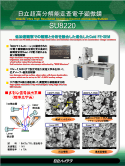
電界放出型走査型電子顕微鏡
Lab 10 - RLC Circuits
© Copyright 2026 ExpyDoc
About ExpyDoc
DMCA / GDPR
Report


![Era Series [Innovative] [F] [Converted].ai - dtp.co.th](http://s3.expydoc.com/store/data/000606526_1-addfffaacb444e21fda50388de95ea70-250x500.png)