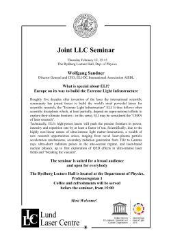
The effect of non-linear quantum electrodynamics on relativistic transparency and
laser absorption in ultra-relativistic plasmas
Peng Zhang,1 A. G. R. Thomas,1 and C. P. Ridgers2
1
Department of Nuclear Engineering and Radiological Sciences,
University of Michigan, Ann Arbor, MI 48109-2104, USA
2
York Plasma Institute,Physics Department, University of York, UK
(Dated: March 21, 2014)
PACS numbers:
m]
z [µ
m]
y [µm]
z [µ
Thin Foil
y [µm]
When the next generation of 10 PW lasers currently
a
under construction are built[1–5], there are likely to be
a few surprises in the way that they interact with matt = 15
Ey
τ
ter. At the extreme intensities expected to be reached in
kx
22
−2
the laser focus (> 10 Wcm ) matter is rapidly ionised
Bz
-kx By
and the electrons in the resulting plasma are accelerated
to such ultra-relativistic energies that the electric field
Ez
they experience in their rest frame may reach the critical
or Schwinger field of quantum electrodynamics (QED),
b
Es = 1.3 × 10¹⁸ Vm−1 [6]. This field is strong enough to
break down the quantum vacuum into electron-positron
t = 34
pairs and is the threshold at which strong-field QED efτ
fects start to play a crucial role [7–10].
The new plasma state that is created is similar to
that thought to exist in extreme astrophysical environments including the magnetospheres of pulsars and active
black holes [11, 12]. Here collective plasma processes are
strongly affected by pair creation and radiation reaction
c
[10, 13–17]. For brevity we will describe the resulting
state as a ’QED plasma’.
t = 34
τ
In non-relativistic plasma, electromagnetic waves with
2
1/2
frequency ω0 < ωpe = (ne e /me 0 )
cannot propagate, where ne is the electron number density. The
critical density nc is the density at which the plasma
frequency equals the wave frequency and above which
the plasma is described as ‘overdense’. In the ultrax [µ
relativistic regime, electrons in the plasma are accelerm]
ated by the laser fields to such high energy that they
have an effective mass much greater than their rest mass.
FIG. 1: 3D QED-PIC simulation (a), Two laser pulses illuConsequently
the plasma frequency is reduced by a factor
p
minate a thin foil from both sides. The left pulse is linearly
1/ hγi, where hγi is the average Lorentz factor of the
polarized in the y-direction, and the right pulse is linearly
electrons. An opaque (and nominally overdense) plasma
polarized in the z-direction. (b-c), the magnitude of electric
may therefore be expected to become transmissive if the
field Ey and the electron density profile at t = 34τ , for the
laser intensity, and therefore hγi, is sufficiently high. This
QED-off and QED-on simulations, respectively. Side panels
2
display slices of Ey(z)
through the center of the box.
“relativistically induced” transparency [18, 19] optically
Fig1
switches the plasma from opaque to transparent and enables light propagation. However, as the electromagnetic
fields increase and we enter the QED-plasma regime, radiation reaction becomes significant, the electron moz [µ
m]
y [µm]
arXiv:1403.5034v1 [physics.plasm-ph] 20 Mar 2014
With the aid of large-scale three-dimensional QED-PIC simulations, we describe a realistic experimental configuration to measure collective effects that couple strong field quantum electrodynamics
to plasma kinetics. For two counter propagating lasers interacting with a foil at intensities exceeding 1022 Wcm−2 , a binary result occurs; when quantum effects are included, a foil that classically
would effectively transmit the laser pulse becomes opaque. This is a dramatic change in plasma
behavior, directly as a consequence of the coupling of radiation reaction and pair production to
plasma dynamics.
2
tion is damped and hence hγi reduced. Furthermore,
radiation-reaction leads to absorption of the electromagnetic wave [20]. At higher intensities still, pair plasma
may be produced that is sufficiently dense to shield the
laser fields. As a result of these processes, a classical prediction that a plasma is transmissive can be erroneous
when QED effects are introduced.
Consider a potential experiment with two counter
propagating laser pulses of intensity I > 1022 Wcm−2
with orthogonal linear polarizations impinging normally
on both surfaces of a solid density foil. The radiation
can be measured after the interaction with a calorimeter
to determine the energy of the pulse after the interaction and because of the orthogonal polarizations it can
be determined what radiation is reflected or transmitted. In this Letter we will show that, for an appropriate
density/thickness foil, the laser radiation should be efficiently absorbed provided strong-field QED effects are
considered in the plasma model, but if they are neglected
the foil will be completely transmissive.
To model this experiment, we performed large-scale
three-dimensional (3D) numerical simulations using the
QED-particle-in-cell (QED-PIC) code EPOCH [21–26],
as shown in Fig. 1. EPOCH extends the VlasovMaxwell system to include the important QED processes
in next generation laser-plasma interactions and is detailed in Ref. [22]. The electromagnetic field is split into
high and low frequency components. The low frequency
components are coherent states that are unchanged in
QED interactions [27]. The evolution of these macroscopic fields is determined by solving Maxwell’s equations. Electron and positron basis states are ‘dressed’ by
these low-frequency fields, which are treated as a classical background in the interactions of these charged particles with the high frequency component of the field,
i.e. using the strong-field QED or ‘Furry’ representation [28]. We include the dominant first-order processes:
gamma-ray photon emission by electrons and positrons
and pair production by gamma-ray photons. Electron
and positron motion between and during these interactions is described by the ‘quasi-classical’ model of Baier
and Katkov [29].
Simulations were performed for two conditions: (1)
”QED-off”, by which we mean no gamma-ray photons
or pairs are generated and (2) ”QED-on”, by which
we mean that the QED-PIC code produces gamma-ray
photons, tracks the photon’s dynamics and generates
electron-positron pairs. The target is 4 µm thick, with
an initial density of 150 nc . The ion mass is taken as
mi /me = 3674 and the ion charge as q/e = 1. The
lasers propagate in the ±x direction, as shown in Fig.
1a. The left-hand-side laser pulse is polarized in y direction and the right-hand-side laser pulse is polarized
in z direction. Both the laser pulses are of intensity
I = 4.5×10²³ Wcm−2 , which is within the range expected
to be reached by next-generation 10 PW lasers, with a
gaussian profile of FWHM radius 4 µm. Both laser pulses
are 25 fs in duration. The radiation pressures of the laser
pulses from opposite sides balance, such that the target
is expected to be confined and centered around its initial position. However, it is compressed until the thermal
pressure balances the ponderomotive pressure.
After the laser pulses reached the surfaces of target
foil, the foil was compressed inwards from both sides.
For the QED-off simulation, when the peaks of the laser
pulses arrived, both pulses started penetrating through
the foil and eventually were transmitted. However, for
the QED-on simulation, the laser pulses were blocked
by the foil during the entire course of the simulation,
indicating that relativistic transparency was suppressed
by the QED effects. The magnitude of electric field Ey
and the electron density profile are plotted at a time of
34τ , where τ is the laser period, in Figs. 1b and c, for
the QED-off and QED-on simulations, respectively.
To facilitate comparison to analytical theory, we repeated the above simulation with circularly-polarized
laser pulses, using 1D QED-PIC code. Very similar results on the transmission behavior were obtained as compared to the above 3D case. This is because the linear
polarizations are similar to circular polarization at particular points in the overlap between the two lasers, in particular in the center of the domain. The laser pulse illuminating the target at normal incidence has a wavelength
of 1 µm and a gaussian profile with a pulse duration of
60 fs and with intensity I = 5 × 10²³ Wcm−2 . The initial
electron density is n0 = 100nc , where nc = ω02 m0 /e2
is the non-relativistic plasma critical density. The target is a slab of thickness 4 µm; the ion mass is taken to
be mi /me = 3674 and the ion charge as q/e = 1. The
simulations were performed under three conditions: 1)
QED-off; 2) QED-on with gamma-ray photon generation
only (the code is allowed to produce photons and calculates the recoil due to emitting photons, which gives the
radiation reaction effect, but the photon is not tracked
and thus there is no pair production involved); and 3)
QED-on with both gamma-ray photon and pair production.
The magnitude of the laser electric field and the plasma
density are plotted as a function of time t and position
x, as shown in Fig. 2, for all the three conditions. For all
the three conditions, the laser plasma interaction process
may be characterized by three distinct stages: an initial
piston-like forward push of electrons by the laser illumination, followed by stagnation at the center between the
two lasers and finally electron re-injection in the backward direction.
During the initial push, both electrons and ions are
continuously compressed inwards until 105τ , as shown
in Figs. 2 (d-f). This compression process is almost
identical under all the three conditions, implying that
radiation reaction and QED effects are not important at
this stage.
3
ne/nc (Classical)
ne/nc (QED)
ne/nc (QED with pair)
FIG. 2: Magnitude of laser field E⊥ and electron density ne /nc as a function of time t and position x from 1D QPIC simulation.
(a)-(c) Magnitude of laser field E⊥ , (d)-(f) electron density ne /nc . Also plotted are the contours for ion density ni /nc (black
lines) and positron density np /nc (green lines).(a) and (d) QED is switched off, (b) and (e) QED is switched on but with photon
emission only, so that the (quantum corrected) radiation reaction effects are included, and (c) and (f) QED is fully activated
to include both photon emission and pair production.
In the case of a single laser beam hitting a charged
particle at rest, the zero momentum frame of reference
(ZMF), in which the charged particle has a periodic trajectory, does not coincide with the laboratory frame due
to particle recoil. ZMF moves in the direction of propagation of the laser beam with a velocity corresponding to
a Lorentz factor equal to a [7, 30]. The laser frequency in
the ZMF is thus redshifted compared to the laboratory
frame. Because the strength parameter a is a Lorentz invariant, the reduced wave frequency in the ZMF implies
a reduced amplitude of the wave field: ERF ≈ E/a and
so χ 1 and the effects of radiation reaction and QED
become insignificant.
After the piston-like push of the electrons by laser, the
bulk plasma stagnates when the ponderomotive pressure
of the laser is balanced by the thermal pressure of the
compressed plasma slab. We find that in this quasi-static
phase of the two sided illumination only the electron motions need to be considered since there is no bulk ion
motion.
There was always a small portion of the electrons at
the edge of the electron layer moving back into the laser
fields, regardless whether QED effects are included or
not. This is simply because there is no net longitudinal force on a thermal electron. However, radiation re-
action dramatically changes the dynamics of the backinjected electrons to radiatively cool them. They form
equally spaced ultra-high-density thin electron layers in
the nodes of the standing wave formed by the incident
and reflected wave, as shown in Figs. 2e and f. These
cause the plasma to become optically opaque compared
to the QED-off case where the layers are not present and
the plasma is transmissive. This is shown in Figs. 2 (a-c).
The situation of electrons circulating in an electric
field in the presence of a fixed ion background — which
is similar to the stagnated layer discussed previously
since no bulk ion motion is involved — readily lends itself to analytical solution. We have confirmed this using 1D QED-PIC simulations with fixed ion background.
The force balance in the longitudinal direction (between
the electrostatic force and light pressure) means that
to good approximation the electron’s circulate in the
transverse direction under the influence of the transverse laser fields. Thus the more straightforward, ‘zerodimensional’, solution for a wave propagating in a homogeneous plasma is of relevance. An equilibrium solution can be found for the wave equation for the laser,
A00 − c2 ∇2 A = ρ0 c(βi − βe )/0 , with the electrons and
ions co-rotating with constant γ transverse to the propagation. The electron current contribution is larger by a
4
ˆ is the unit vector in the direction of the electric
where e
field. Although we are considering an electromagnetic
wave propagation, near the threshold for propagation the
magnetic field will be much smaller than the electric field.
It will also be close to parallel to the electron momentum
for all but the strongest radiation damping. It is therefore reasonable to neglect its contribution to the electron
motion and it greatly simplifies the analysis.
An equilibrium solution to Eq. (1) exists where the
component of electric field parallel to β precisely compensates for the radiative losses, while the perpendicular
component provides the centripetal force for circular motion of the electrons. Setting the LHS of Eq. (1) to 0, we
find, by neglecting terms of order γ −2 or smaller,
γ = a sin θ, Γ sin2 θ − cos θ = 0,
(2)
where Γ = (2/3)(e2 /me c3 )ω0 aγ 2 . Combining Eq. (2)
and eliminating θ, we obtain a relation between γ and a
τR2 ω02 γ 8 + γ 2 = a2
(3)
where τR = 2e2 /3m0 c3 = 4.163 × 10⁻²⁴ s. Equation
(3) is plotted in Fig. 3a for λ = 1µm. For a < 300,
γ ∼
=a, radiation reaction effects on the dynamics of the
electrons are negligible. For a > 300, the value of γ
becomes smaller than a, as electron motions are inhibited
by the strong radiation reaction force.
It is well known [23, 32–34] that the classical description of an electron radiating in a strong electromagnetic
field overestimates the total emitted power. This understanding is connected to the fact that, in the quantum
description, the emitted photon energy may not exceed
the electron energy, whereas the classical approach does
not have such a restriction. This effect may be approximately taken into account as follows. The total power of
emitted radiation can be expressed as the power calculated from the classical description of radiation reaction,
times a reducing factor g(η) that accounts for truncation of the emitted spectrum [23, 33, 34]. Eqn. (2) still
holds, except that now Γ = g(η)(2/3)(e2 /me c3 )ω0 aγ 2 . γ
with quantum corrected radiation reaction effect is also
plotted in Fig.3a. In general, quantum effects reduce the
classical radiation back reaction, which make the Lorentz
factor γ of the electrons only slightly smaller than its conventional value γ ∼
= a. However, the fraction of the laser
power that produces synchrotron radiation, which is proportional to the electric field parallel to electron velocity,
i.e. cos θ, remains significant, as shown in Fig.3b.
1000
a
b
1.0
cos(theta)_No_RR
Classical
Classical
QED corrected RR
gamma_RR
RR
gamma_NO_RR
gamma_RR_QED
800
cos(theta)_RR_QED
QED corrected
0.8
600
RR
cos(theta)_RR
RR
0.6
cos
factor of approximately mi /(me a0 ), so for simplicity we
neglect the ions.
Classically, the electron equation of motion for an electron in a circulating electric field, including radiation
reaction according to the Landau-Lifshitz prescription
[7, 31], is
eE
2e3 2
d(γβ)
2
ˆ
ˆ−
γ
βE
1
−
(β
·
e
)
(1)
=
e
dt
me c
3m2e c4
400
0.4
200
0.2
0
0.0
0
500
a
1000
0
500
a
1000
FIG. 3: Effects of radiation reaction on single electron dynamics. (a) γ and (b) cos θ as a function of a for λ = 1µm,
under three conditions: classical, i.e. no radiation reaction
force, γ = (1 + a2 )1/2 ; RR, with classical radiation reaction
force, Eqn. (3); and QED corrected RR, with quantum corrected radiation reaction force.
The significance of this can be seen by considering
the resulting wave equation, which including this current
contribution yields a dispersion relation
ω 2 = k 2 c2 +
2
ωp0
,
γ (1 − iτR ω0 γ 3 )
(4)
3
that
q for τR ωγ 1 has a real component ω0 =
2 /γ and an imaginary component, i.e. reprek 2 c2 + ωp0
2
senting absorption of the wave, of ωI = ωp0
τ γ 2 /2, with
qR
2 /a
γ given by Eq. (3). Since γ ' a, ω0 ' k 2 c2 + ωp0
2
and ωI ' ωp0
τR a2 /2. This gives a critical frequency for
the threshold
√ for wave propagation, i.e. where k = 0, of
ωc = ωp0 / a.
In the strong damping limit, τR ωγ 3 1, the
dispersion relation yields an imaginary component
2
2
ωI = ωp0
/(2ω02 τR γ 4 ) and for ωp0
/(γω02 ) 1, ω02 =
1/4
4
k 2 c2 + ωp0
/(4ω04 τR2 γ 8 ). In this limit, γ ' [a/(ω0 τR )]
2
so that ωI = ωp0
/(2ω0 a). The critical frequency for wave
√
propagation
is
now
ωc = ωp0 / 2a, which is a factor of
√
2 smaller than that of weak damping limit. However, at
this frequency the wave is critically damped, i.e. ωI = ωc ,
and will therefore be attenuated rapidly.
In summary, we have studied the interplay of QED
effects and collective processes in plasmas generated by
next-generation 10 PW lasers. In particular we have derived a dispersion relation for electromagnetic wave propagation and shown that the damping of collective electron
oscillations leads to strong absorption of the wave. This
has dramatic consequences for relativistic transparency.
QED-PIC simulations are performed to demonstrate that
the relativistically transparent plasma may be converted
to become optically opaque if QED effects become important. 3D simulations were performed to provide exper-
5
imental framework to test the relativistic transparency
with strong radiation reaction and QED effects and the
scaling of the absorption/transmission with laser intensity should be reasonably easy to measure experimentally.
These predictions may be tested using high-power lasers
in the next few years.
This research was supported by the AFOSR and in
part through computational resources and services provided by Advanced Research Computing at the University of Michigan, Ann Arbor.
[1] B. Rus, P. Bakule, D. Kramer, G. Korn, J. T. Green,
J. Novak, M. Fibrich, F. Batysta, J. Thoma, J. Naylon,
et al., Proceedings of SPIE 8780 (2013).
[2] G. A. Mourou, C. L. Labaune, M. Dunne, N. Naumova,
and V. T. Tikhonchuk, Plasma Phys. Controlled Fusion
49, B667 (2007).
[3] M. Marklund, Nature Photonics 4, 72 (2010).
[4] E. Gerstner, Nature 446, 16 (2007).
[5] E. Gerstner, Nature Physics 6, 638 (2010).
[6] J. Schwinger, Phys. Rev. 82, 664 (1951).
[7] A. R. Bell and J. G. Kirk, Phys. Rev. Lett. 101, 200403
(2008).
[8] A. M. Fedotov, N. Narozhny, G. Mourou, and G. Korn,
Phys. Rev. Lett. 105, 080402 (2010).
[9] S. S. Bulanov, T. Z. Esirkepov, A. G. R. Thomas,
J. K. Koga, and S. V. Bulanov, Phys. Rev. Lett.
105, 220407 (2010), URL http://link.aps.org/doi/
10.1103/PhysRevLett.105.220407.
[10] E. Nerush, I. Y. Kostyukov, A. M. Fedotov, N. B.
Narozhny, N. V. Elkina, and H. Ruhl, Phy. Rev. Lett.
106, 035001 (2011).
[11] P. Goldreich and W. Julian, ApJ. 157, 869 (1969).
[12] R. D. Blandford and R. Znajek, MNRAS 179, 433
(1977).
[13] A. Timokhin, MNRAS 408, 2092 (2010).
[14] C. Ridgers, C. S. Brady, R. Duclous, J. G. Kirk, K. Bennett, T. D. Arber, A. P. L. Robinson, and A. R. Bell,
Phys. Rev. Lett. 108, 165006 (2012).
[15] C. P. Ridgers, C. S. Brady, R. Duclous, J. G. Kirk,
K. Bennett, T. D. Arber, and A. R. Bell, Phys. Plas.
20, 056701 (2013).
[16] J. Kirk, A. Bell, and C. Ridgers, Plasma Physics and
Controlled Fusion 55, 095016 (2013).
[17] S. V. Bulanov, T. Z. Esirkepov, M. Kando, S. S. Bulanov,
S. G. Rykovanov, and F. Pegoraro, arXiv1310.5181v1
(2013).
[18] P. Kaw and J. Dawson, Phys. Fluids 13, 472 (1970).
[19] S. Palaniyappan, B. M. Hegelich, H. Wu, D. Jung, D. C.
Gautier, L. Yin, B. J. Albright, R. P. Johnson, T. Shimada, S. Letzring, et al., Nature Physics 8, 763 (2012).
[20] A. Bashinov and A. Kim, Phys. Plasmas 20, 113111
(2013).
[21] C. S. Brady and T. D. Arber, Plasma Phys. Controlled
Fusion 53, 015001 (2011).
[22] C. Ridgers, J. Kirk, R. Duclous, T. Blackburn, C. Brady,
K. Bennett, T. Arber, and A. Bell, J. Comp. Phys. 260,
273(2014).
[23] J. G. Kirk, A. R. Bell, and I. Arka, Plasma Phys. Control.
Fusion 51, 085008 (2009).
[24] I. Sokolov, N. Naumova, J. Nees, G. Mourou, and
V. Yanovsky, Phys. Plasmas 16, 093115 (2009).
[25] R. Duclous, J. G. Kirk, and A. R. Bell, Plasma Phys.
Controlled Fusion 53, 015009 (2011).
[26] A. D. Piazza, K. Hatsagortsyan, and C. Keitel, Phys.
Rev. Lett. 105, 220403 (2010).
[27] R. Glauber, Phys. Rev. 131, 2766 (1963).
[28] W. Furry, Phys. Rev. 81, 115 (1951).
[29] V. Baier and V.M.Katkov, Sov. Phys., JETP 26, 854
(1968).
[30] Y. Y. Lau, F. He, D. P. Umstadter, and R. Kowalczyk,
Phys. Plasmas 10, 2155 (2003).
[31] L. D. Landau and E. M. Lifshitz, The Classical Theory
of Fields, Course of Theoretical Physics-Pergamon International Library of Science, Technology, Engineering and
Social Studies (Pergamon Press, Oxford, 1975), 4th ed.
[32] T. Erber, Rev. Mod. Phys. 38, 626 (1966).
[33] V. I. Ritus, Tr. Fiz. Inst. Akad. Nauk SSSR 111, 6 (1979).
[34] A. G. R. Thomas, C. P. Ridgers, S. S. Bulanov, B. J.
Griffin, and S. P. D. Mangles, Phys. Rev. X 2, 041004
(2012).
© Copyright 2026 ExpyDoc