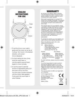
RONDA powertech 500 and 762E, 763E Affordable metal movements for reliable quality watches Caliber 515.24H – 11½''' Product Specifications Features Analog quartz movement – Repairable metal watch movement Line powertech Caliber 515.24H Size 11½''' Version Swiss Made Swiss Parts 1 Jewels / nickel plated 1 Jewels / nickel plated Standard battery life 45 months Hand fitting height 1 – Power saving mechanism with pullled out stem: Reduction of consumption approximately 70% – Interchangeability: All versions 11½''' with same movement height 3.00 mm and stem height 1.50 mm – Very powerful stepping motor – GMT function with quick change Date: 02.08.2016 www.ronda.ch Page: 1 RONDA powertech Caliber 515.24H – 11½''' Functions Technical Specifications – 24 hours Diameter Total 26.00 mm – Date Case fitting 25.60 mm – 24 hours by hand – GMT function Movement height 3.00 mm Height over standard battery 3.25 mm Movement rest 0.80 mm Height over stem 1.50 mm Length of stem travel 1.00 mm – 3 hands Force to push the stem for screwed crown N Stem thread 0.90 mm Standard battery 371 Standard battery life 45 months Battery voltage 1.5 V Current consumption – typical 1.28 μA (Date Mechanism not in Gear) Current consumption – maximum 1.85 μA (Date Mechanism not in Gear) Useful torque second – typical 11 μNm Useful torque minute – typical 550 μNm Operating temperature 0 - 50 °C Instantaneous rate -10/ +20 sec/month Resistance to magnetic fields 18.8 Oe Resistance against shock NIHS 91-10 Date: 02.08.2016 www.ronda.ch Page: 2 + 70 -0 min 2.6 3.15 - 0 + 150 min 3.4 1.5 + 50 -0 0.8 + 150 -0 3 Ø 1.07 Ø 25 .6 0 + 30 - .2 26 Ø Position pour extraire la tige Position zum entfernen der Stellwelle Position to remove the stem + -3 0 0 Côte fond de boîite Seite Gehäuseboden Case back side 1.00 Course tige Stellwelle Weg stem travel 3 7.6 6.87 S 0.9 Sécurité entre aiguille seconde et verre Sicherheit zwischen Sekundenzeiger und Glas Security between second hand and glass : min 0.30 mm : min 0.30 mm : min 0.30 mm Le cadran doit être maintenu en hauteur par la boîte. Das Zifferblatt muss in der Höhe vom Gehäuse festgehalten werden. The dial must be held in the height by the case. Pile Batterie Battery 0.05 Ø 9.50 x 2.10 Cage Uhrwerkgestell Frame Issued 11½''' Modified 10 Mrz 1999 23 Jun 2011 ÄA 11169 Released dh YES Tolerance Scale gd +/- 20 µm 10 : 1 (5 : 1) (A3H) Sous réserve de modifications RONDA 515.24H Aenderungen vorbehalten Modifications reserved No. 5000.288 05 Longueur Länge Length Sous l'aiguille des heures 24H Unter Stundenzeiger 24H Under hour hand 24H E F RS H B H 1 1.80 1.40 1.10 0.70 1.44 2.10 1.30 1.00 0.70 0.40 0.15 E F RS B Appui cadran Zifferblattauflage Dial seat 2 2.15 1.75 1.45 1.05 1.79 2.45 1.65 1.35 1.05 0.75 0.15 Roue des heures Stundenrad Hour wheel Ø 0.4 max. Roue des heures 24H Stundenrad 24H Hour wheel 24H +6 Ø 0.206 -4 0.3 Cylindrique Zylindrisch Cylindrical Roue des heures Stundenrad Hour wheel Ø 0.5 Conicité Konizität 2% Conicity Ø 0.200 Aiguillage no Zeigerwerkhöhe Nr. Hand fitting height No Minutenzeigerpassung Minute hand fitting 0.25 Sekundenzeigerpassung Second hand fitting G Ø 0.700 -4 +6 Ajustement aiguille des secondes Unter Minutenzeiger Under minute hand G Ajustement aiguille des minutes Sous l'aiguille des secondes Unter Sekundenzeiger Under second hand Sous l'aiguille des heures Unter Stundenzeiger Under hour hand Stundenzeigerpassung Hour hand fitting +4 Ø 1.200 -2 Sous l'aiguille des minutes Height over dial seat Ajustement aiguille des heures Epaisseur max. (peinture comprise) Max. Dicke (inkl. Farbe) Max. thickness (paint included) Cadran Aiguilles Zifferblatt Zeiger Dial Hands Chaussée Minutenrohr Cannon-pinion Ø 1.600 Dépassement Höhe über Zifferblattauflage +4 -2 Pignon des secondes Sekundentrieb Second pinion Ajustement aiguille des 24 heures 24 Stundenzeigerpassung 24 Hour hand fitting Aig. des heures Stundenzeiger Hour hand Minutenzeiger Minute hand Aig. des minutes Sekundenzeiger Second hand Aig. des secondes Heures 24H / Heures / minutes / secondes Stunden 24H / Stunden / Minuten / Sekunden Hours 24H / Hours / minutes / seconds Lors de la pose d'aiguilles, le mouvement doit être soutenu. Beim Zeigersetzen muss das Werk abgestützt werden. The movement needs to be supported for hand setting. Masse / Masse / Weight * mg max. 10 30 30 µNm max. 0.08 0.70 0.70 Balourd / Unwucht / Unbalance * Inertie / Massenträgheit / Inertia * 2 gmm max. 0.4 - - max. 30 40 40 N Force de chassage / Aufpresskraft / Force Sous réserve de toutes modifications Aiguillages Zeigerwerkhöhen Hand fitting heights Aenderungen vorbehalten 10½''', 11½''' All modifications reserved Issued 10 Mär 1999 gd Modified 17 Feb 2011 ÄA 10340 ps Released Yes Tolerance Scale * Bei abweichenden Werten, bitte technischen Kundendienst anfragen 20 : 1 (A3H) Sous réserve de modifications RONDA 505.24H, 515.24H Aenderungen vorbehalten Modifications reserved No. 3316.061 * En cas de données différentes, veuillez contacter le service après-vente µm * In case of different values, please contact the customer service 07 L2 D S L L3 L1 Ø d'encageage / Gehäusepassungs-Ø / Case fitting Ø Tige de travail (intégrée dans le mouvement) Arbeitstellwelle (im Werk eingebaut) Working stem (implemented in the movement) No. d'article Artikelnummer Part number L L1 3000.164.CO 20.50 9.92 L2 L3 22.72 11.83 S D 0.90 1.05 Couleur de la couronne Kronenfarbe Crown color Code brun braun brown Couronne normale Normale Krone Normal crown UN 8052 Boîte / Gehäuse / Case Tige (normale) / Stellwelle (normal) / Stem (normal) No. d'article Artikelnummer Part number L L1 3000.164 20.50 9.92 3000.171 L2 L3 S D 22.72 11.83 0.90 1.05 32.50 21.92 34.72 23.83 0.90 1.05 0.02 - 0.10 Couronne vissée Geschraubte Krone Screwed crown Force min. Kraft min. 10 N Force min. Force max. Kraft max. 15 N Force max. Tige (à arracher) Stellwelle (Ausreissversion) Stem (extractable version) 3000.163 20.05 9.92 3000.196 L2 L3 S D 22.72 11.83 0.90 1.05 32.50 21.92 34.72 23.83 0.90 1.05 Rallonge de tige / Stellwelle Verlängerung / Stem extension No. d'article Artikelnummer Part number 3000.040 L4 L5 (min) L6 S1 S2 15 Aug 2012 Issued S2 L1 D1 L S1 No. d'article Artikelnummer Part number D1 Tige Stellwelle Stem (dimensions / forces) (Dimensionen / Kräfte) (dimensions / forces) Modified Released Tolerance 1.90 2.45 0.90 0.90 1.35 L5 L6 L4 RONDA 512, 513, 513S, 515, 515S, 515.24H, 515.24D, 517, 519 ÄA 11741 ds5222 YES --10:1 (A3) Scale 12.00 --- ds5222 Sous réserve de modifications Aenderungen vorbehalten Modifications reserved No. 5030.002 00 Werkhalter T2 Porte-pièce T2 Movement holder T2 Verwendung & Übersicht Utilisation & Vue d’ensemble Utilisation & Overview DOMVT004 Version: 2.1 Prozess: 3.1.3 Änd.-Dat.: 20.04.15 5110, 5112, 5150, 5151, 5152, 5160, 5161, 5163, 5164, 5166, 5310, 5311, 5312, RTC, RHK Ermano, Pine Precision AF Switzerland SA, Horotec SA, Tschudin & Schneider Zeiger setzen A Kalibergruppe Groupe de calibre Calibre group ZXX Poser les aiguilles Stellwelle entfernen T Diverses Enlever la tige Divers Hand setting Stem removal Various Artikelnummer Numéro d’article Part number Artikelnummer Numéro d’article Part number Artikelnummer Numéro d’article Part number H ZXX.2A H ZXX.1T H ZXX.1A H ZXX.1T H 80XX.1A H 80XX.1T Z50 ZXX Z60 8000-8499 8040.B 8040.N Wichtig! Die Höhe der Abstützschrauben muss vor Beginn jeder Serie eingestellt werden. Important! Veuillez ajuster l’hauteur des vis de support au préalable de chaque série. Important! Adjust height of support screws prior to each series. DOMVT004 / Version: 2.1 / Prozess: 3.1.3 / Änd.-Dat.:20.04.15 Seite 1/9 7000-7999 H 7XXX.1A H 7XXX.1T 700X.B 700X.L 700X.N 700X.P Wichtig! Die Höhe der Abstützschrauben muss vor Beginn jeder Serie eingestellt werden. Important! Veuillez ajuster l’hauteur des vis de support au préalable de chaque série. Important! Adjust height of support screws prior to each series. DOMVT004 / Version: 2.1 / Prozess: 3.1.3 / Änd.-Dat.:20.04.15 Seite 2/9 Zeiger setzen A Kalibergruppe Groupe de calibre Calibre group 6000-6999 Poser les aiguilles Stellwelle entfernen T Enlever la tige Alarm-Check P Contrôle d’alarme Hand setting Stem removal Alarm check Artikelnummer Numéro d’article Part number Artikelnummer Numéro d’article Part number Artikelnummer Numéro d’article Part number H 6XXX.1A H 6XXX.1T 6XXX.B 6XXX.D Swiss Made 4000-5999.B/.C/.D/.E Swiss Parts H 5XXX.1A H 5XXX.1T H 5XXX.1P H 5XXX.FA H 5XXX.1T H 5XXX.1P 4XXX.B 5XXX.B 5XXX.C 5XXX.D 5XXX.E 4000-5999.F 5XXX.F (4XXX.B) (5XXX.B) (5XXX.C) (5XXX.D) (5XXX.E) Wichtig! Die Höhe der Abstützschrauben muss vor Beginn jeder Serie eingestellt werden. Important! Veuillez ajuster l’hauteur des vis de support au préalable de chaque série. Important! Adjust height of support screws prior to each series. DOMVT004 / Version: 2.1 / Prozess: 3.1.3 / Änd.-Dat.:20.04.15 Seite 3/9 Zeiger setzen A Kalibergruppe Groupe de calibre Calibre group 3500-3999 Stellwelle entfernen T Poser les aiguilles Diverses Enlever la tige Divers Hand setting Stem removal Various Artikelnummer Numéro d’article Part number Artikelnummer Numéro d’article Part number Artikelnummer Numéro d’article Part number H 35XX.1A H 35XX.1T H 106X.1A H 106X.1T 3520.D 3540.D 1062-1069 1062 1063 1064 1069 Swiss Made Swiss Parts 6h 1062 - 1063 - - 1064 - 1069 - 1042 - 6h - - - - - - H 1042.1A H 1042.1T 1042 Wichtig! Die Höhe der Abstützschrauben muss vor Beginn jeder Serie eingestellt werden. Important! Veuillez ajuster l’hauteur des vis de support au préalable de chaque série. Important! Adjust height of support screws prior to each series. DOMVT004 / Version: 2.1 / Prozess: 3.1.3 / Änd.-Dat.:20.04.15 Seite 4/9 Zeiger setzen A Kalibergruppe Groupe de calibre Calibre group 1032 Poser les aiguilles Stellwelle entfernen T Diverses Enlever la tige Divers Hand setting Stem removal Various Artikelnummer Numéro d’article Part number Artikelnummer Numéro d’article Part number Artikelnummer Numéro d’article Part number H 1032.1A H 1032.1T H 101X.1A H 101X.1T H 100X.1A H 100X.1T 1032 1012-1019 1012 1013 1014 1015 1016 1019 1002-1009 1002 1003 1004 1005 1006 1009 Wichtig! Die Höhe der Abstützschrauben muss vor Beginn jeder Serie eingestellt werden. Important! Veuillez ajuster l’hauteur des vis de support au préalable de chaque série. Important! Adjust height of support screws prior to each series. DOMVT004 / Version: 2.1 / Prozess: 3.1.3 / Änd.-Dat.:20.04.15 Seite 5/9 Zeiger setzen A Kalibergruppe Groupe de calibre Calibre group 782-788 Poser les aiguilles Stellwelle entfernen T Diverses Enlever la tige Divers Hand setting Stem removal Various Artikelnummer Numéro d’article Part number Artikelnummer Numéro d’article Part number Artikelnummer Numéro d’article Part number H 78X.1A H 78X.1T 782 783 784 785 788 Swiss Made 772-775 Swiss Parts H 77X.1A H 77X.1T 772 773 774 775 Swiss Made Swiss Parts Wichtig! Die Höhe der Abstützschrauben muss vor Beginn jeder Serie eingestellt werden. Important! Veuillez ajuster l’hauteur des vis de support au préalable de chaque série. Important! Adjust height of support screws prior to each series. DOMVT004 / Version: 2.1 / Prozess: 3.1.3 / Änd.-Dat.:20.04.15 Seite 6/9 Zeiger setzen A Kalibergruppe Groupe de calibre Calibre group Stellwelle entfernen Poser les aiguilles T Diverses Enlever la tige Divers Hand setting Stem removal Various Artikelnummer Numéro d’article Part number Artikelnummer Numéro d’article Part number Artikelnummer Numéro d’article Part number H 76X.1A H 76X.1T 762-763 762 762E 763 763E Swiss Made Swiss Parts 762 - - 762E - - 763 - 763E 751-753 H 75X.1A H 75X.1T 751 753 751 Swiss Made Swiss Parts - - 753 Wichtig! Die Höhe der Abstützschrauben muss vor Beginn jeder Serie eingestellt werden. Important! Veuillez ajuster l’hauteur des vis de support au préalable de chaque série. Important! Adjust height of support screws prior to each series. DOMVT004 / Version: 2.1 / Prozess: 3.1.3 / Änd.-Dat.:20.04.15 Seite 7/9 Zeiger setzen A Kalibergruppe Groupe de calibre Calibre group 712-715 Stellwelle entfernen Poser les aiguilles T Diverses Enlever la tige Divers Hand setting Stem removal Various Artikelnummer Numéro d’article Part number Artikelnummer Numéro d’article Part number Artikelnummer Numéro d’article Part number H 71X.1A H 71X.1T 712 713 714 715 Swiss Made 702-708 Swiss Parts H 70X.1A H 70X.1T 702 703 704 705 708 (706) Swiss Made 706 Swiss Parts H 706.1A H 70X.1T 706.1 706.2 706.3 706.B Swiss Made 6h Swiss Parts 6h Wichtig! Die Höhe der Abstützschrauben muss vor Beginn jeder Serie eingestellt werden. Important! Veuillez ajuster l’hauteur des vis de support au préalable de chaque série. Important! Adjust height of support screws prior to each series. DOMVT004 / Version: 2.1 / Prozess: 3.1.3 / Änd.-Dat.:20.04.15 Seite 8/9 Zeiger setzen A Kalibergruppe Groupe de calibre Calibre group 582-585 Poser les aiguilles Stellwelle entfernen T Diverses Enlever la tige Divers Hand setting Stem removal Various Artikelnummer Numéro d’article Part number Artikelnummer Numéro d’article Part number Artikelnummer Numéro d’article Part number H 58X.1A H 58X.1T H 51X.1A H 51X.1T H 50X.1A H 50X.1T 582 583 585 512-519 512 513 515 517 519 502-509 502 503 505 507 509 Wichtig! Die Höhe der Abstützschrauben muss vor Beginn jeder Serie eingestellt werden. Important! Veuillez ajuster l’hauteur des vis de support au préalable de chaque série. Important! Adjust height of support screws prior to each series. DOMVT004 / Version: 2.1 / Prozess: 3.1.3 / Änd.-Dat.:20.04.15 Seite 9/9 User's Manual English Movements Caliber I II III RONDA powertech – 505.24D / 515.24D – 505.24H / 515.24H – 507 / 517 – 509 / 519 You have decided to buy a watch, which was assembled by a watchmaker using a Ronda movement. Please note that no watches are produced or distributed under the Ronda brand. In case of repairs, guarantee claims and questions concerning the functioning of a watch, purchasers and consumers should contact their retailer or the watch manufacturer, for which the relevant information can be found in the sales or guarantee documentation provided with the watch. Cal. 505.24D / 515.24D I II III I II III Cal. 505.24H / 515.24H Pos. I Position of rest (watch running) Quick-change correction for date The date can also be corrected during the day-changing phase between 10 pm and midnight. The date of the following day has to be set, because no automatic date change takes place at midnight. – Pull the crown out to position II (watch still running). Turn the crown clockwise until the required date appears. – – Push the crown back into position I. Pos. II Quick-change correction for date The date can also be corrected during the day-changing phase between 10 pm and midnight. The date of the following day has to be set, because no automatic date change takes place at midnight. – Pull the crown out to position II (watch still running). – Turn the crown until the required date appears. – Push the crown back into position I. Pos. I Position of rest (watch running) Cal. 507 / 517 Pos. II Quick-change correction for 24-hour display – Pull the crown out to position II (watch still running). –Turn the crown anticlockwise until the desired time appears. – Push the crown back into position I. Pos. III Setting the time – Pull the crown out to position III (watch stopped). – Turn the crown, until the current time is displayed (remember the 24-hour cycle). – Push the crown back into position I. Quick-change correction for day of the week The blocking time for the day of the week quick-change correction is from approx. 10 pm and midnight. –The second language always first appears around 24.00hrs for about 2 hours, until the display changes to the required language. – Pull the crown out to position II (watch still running). – Turn crown anticlockwise until the desired day of the week appears in the required language. – Push the crown back into position. I II III Cal. 507 / 517 Pos. III Setting the time – Pull the crown out to position III (watch stopped). – Turn the crown, until the current time is displayed (remember the 24-hour cycle). – Push the crown back into position I. Cal. 509 / 519 Pos. I Position of rest (watch running) Pos. II Quick-change correction for date The date display comprises a 2-disc system. For construction reasons, on the first day of a new month, the date must be set on 01 via the quick-change method passing through 31–39. The date can also be changed during the day-changing phase between approx. 10 pm and midnight. The date of the following day has to be set, because no automatic date change takes place at midnight. – Pull the crown out to position II (watch still running). Turn the crown clockwise until the required date appears. – – Push the crown back into position I. Pos. III Setting the time – Pull the crown out to position III (watch stopped). – Turn the crown, until the current time is displayed (remember the 24-hour cycle). – Push the crown back into position I. Applies to all calibers: Battery type: 371 / SR920SW (Ø 9.5 mm x 2.05 mm) Precision: +20 / -10 seconds per month 03 / 2015 User's Manual English Movements Caliber I II III RONDA powertech – 505.24D / 515.24D – 505.24H / 515.24H – 507 / 517 – 509 / 519 You have decided to buy a watch, which was assembled by a watchmaker using a Ronda movement. Please note that no watches are produced or distributed under the Ronda brand. In case of repairs, guarantee claims and questions concerning the functioning of a watch, purchasers and consumers should contact their retailer or the watch manufacturer, for which the relevant information can be found in the sales or guarantee documentation provided with the watch. Powered by TCPDF (www.tcpdf.org) Cal. 505.24D / 515.24D I II III I II III Cal. 505.24H / 515.24H Pos. I Position of rest (watch running) Quick-change correction for date The date can also be corrected during the day-changing phase between 10 pm and midnight. The date of the following day has to be set, because no automatic date change takes place at midnight. – Pull the crown out to position II (watch still running). Turn the crown clockwise until the required date appears. – – Push the crown back into position I. Pos. II Quick-change correction for date The date can also be corrected during the day-changing phase between 10 pm and midnight. The date of the following day has to be set, because no automatic date change takes place at midnight. – Pull the crown out to position II (watch still running). – Turn the crown until the required date appears. – Push the crown back into position I. Pos. I Position of rest (watch running) Cal. 507 / 517 Pos. II Quick-change correction for 24-hour display – Pull the crown out to position II (watch still running). –Turn the crown anticlockwise until the desired time appears. – Push the crown back into position I. Pos. III Setting the time – Pull the crown out to position III (watch stopped). – Turn the crown, until the current time is displayed (remember the 24-hour cycle). – Push the crown back into position I. Quick-change correction for day of the week The blocking time for the day of the week quick-change correction is from approx. 10 pm and midnight. –The second language always first appears around 24.00hrs for about 2 hours, until the display changes to the required language. – Pull the crown out to position II (watch still running). – Turn crown anticlockwise until the desired day of the week appears in the required language. – Push the crown back into position. I II III Cal. 507 / 517 Pos. III Setting the time – Pull the crown out to position III (watch stopped). – Turn the crown, until the current time is displayed (remember the 24-hour cycle). – Push the crown back into position I. Cal. 509 / 519 Pos. I Position of rest (watch running) Pos. II Quick-change correction for date The date display comprises a 2-disc system. For construction reasons, on the first day of a new month, the date must be set on 01 via the quick-change method passing through 31–39. The date can also be changed during the day-changing phase between approx. 10 pm and midnight. The date of the following day has to be set, because no automatic date change takes place at midnight. – Pull the crown out to position II (watch still running). Turn the crown clockwise until the required date appears. – – Push the crown back into position I. Pos. III Setting the time – Pull the crown out to position III (watch stopped). – Turn the crown, until the current time is displayed (remember the 24-hour cycle). – Push the crown back into position I. Applies to all calibers: Battery type: 371 / SR920SW (Ø 9.5 mm x 2.05 mm) Precision: +20 / -10 seconds per month 03 / 2015
© Copyright 2026 ExpyDoc