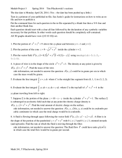
Momentum Principle Chapter Eight I n mechanics, the momentum of particle or object is defined as the product of its mass m and its velocity V, Momentum mass velocity Momentum m.V The particles of a fluid stream will possess, and, whenever the velocity of the stream is changed in magnitude or direction, there will be a corresponding change in the momentum of the fluid particles. In accordance with Newton’s second law, a force is required to produce this change, which will be proportional to the rate at which the change of momentum occurs. The force may be provided by contact between the fluid and a solid boundary or by one part of the fluid stream acting on another. By Newton’s third law, the fluid will exert an equal and opposite force on the solid boundary or body of fluid producing the change of velocity. Such forces are known as dynamic forces, since they arise from the motion of the fluid and are additional to the static forces due to pressure in a fluid, which occur even when the fluid is at rest. The rate of change of momentum Mass of fluid per unit time flowing change of velocity The rate of change of momentum .Q.V (8.1) Where is the density of the fluid and Q is the volumetric rate of flow called discharge. Note that this is the increase of momentum per unit time in the direction of motion, and according to Newton’s second law will be caused by a force F, such that: F .Q.V (8.2) Chapter Force in any direction Rate of change of momentum in that direction 8 Chapter Eight Momentum Principle This is the resultant force acting on the fluid in the direction of motion. By Newton’s third law, the fluid will exert an equal and opposite reaction on it’s surrounding. The momentum Equation (8.2) was derived for one-dimensional flow in a straight line, assuming that the incoming and outgoing velocities V1 and V2 were in the same direction. 8.1 Momentum Equation for Two-Dimensional Flow along a Streamline: Figure (8.1) shows a control volume of fluid, in which V1 makes an angle 1 with the x-axis while V2 makes a corresponding angle 2. Vy2 V2 Vx2 P2 2 Control Volume Rx y 1 V y1 V1 x Ry W P1 Vx1 Figure 8.1: Momentum equation for two-dimensional flow. Since both momentum and force are vector quantities, they can resolved into components in the x and y directions and Equation (8.2) is applied. Thus if Fx and Fy are the components of the resultant force on the element of the fluid, Fx Rate of change of momentum of fluid in x-direction Fx Mass of fluid change of velocity 8 Chapter per unit time in x-direction Fx .Q(V2 . cos 2 V1 . cos 1 ) Fx Q(V x 2 V x1 ) .Q.V x 165 (8.3) Momentum Principle Chapter Eight Where, Fx components of external forces in x-direction Similarly, Fy .Q(V2 . sin 2 V1 . sin1 ) Fy .Q(V y 2 V y1 ) .Q.V y (8.4) Where, Fy components of external forces in y-direction These components can be combined to give the resultant force, F Fx2 Fy2 (8.5) Again, the force exerted by the fluid on the surrounding will be equal and opposite. To summarize the above mentioned relations, we can say, in general, that Total force exerted on Rate of change of momentum the fluid in a control in the given direction of the fluid volumein a given direction passing through the control volume F .Q(Vout Vin ) (8.6) The value of F is positive in the direction in which V is assumed to be positive. 8.2 Applications of the Momentum Equation The momentum equation may be used directly to evaluate the force causing a change of momentum in a fluid. Such applications include Chapter The external forces include gravity forces (weight of the control volume of fluid, which is generally very small and hence neglected), shear forces, pressure forces, and forces exerted by the solid boundary. 8 Chapter Eight Momentum Principle determining forces on pipe bends and junctions, nozzles and hydraulic machines. In addition the momentum equation is used to solve problems in which energy losses occur that cannot be evaluated directly or when the flow is unsteady. Examples of such problems include local head losses in pipes, the hydraulic jump and unsteady flow in pipes and channels. 8.2.1 Force Exerted by a Jet Striking a Flat Plate When a jet of fluid strikes a stationary flat plate at angle as in Figure (8.2) it does not rebound, but flows out over the plate in all directions. In a direction normal to the surface of the plate, the velocity of the stream will be reduced to zero and the momentum normal to the plate destroyed. There will, therefore, be a force exerted between the jet and the plate equal to the rate of change of momentum normal to the plate is acting on the plate in the direction of motion, with an equal and opposite reaction by the plate on the jet. Control surface u in unit time A u V V F x-direction x-direction (a) (b) Figure 8.2: Force exerted on a flat plate 8 Chapter In a direction parallel to the plate, the force exerted will depend on the shear stress between the fluid and the surface of the plate. For an ideal fluid, there would be no shear stress and no force parallel to the plate. The fluid would flow out over the plates so that the total momentum per second parallel to the plate remained unchanged. 167 Momentum Principle Chapter Eight A jet of water with a diameter of 60 mm and a velocity of 5 m/s hits a vertical plate shown in figure. Calculate the force on impact on the jet on the plate. Vertical Plate V 1=5m/s F Water Jet 60 mm dia. V 2=0 Force of the plate on the water in x-direction, F .Q(V2 V1 ) Thus The discharge Q, F .Q(V1 V2 ) (1) Q V .A ( (0.06) 2 0.014m 3 / s Q 5 4 But the plate is stationary, i.e., V2=0, so putting the known values into Eq. (1). The force of the water jet on the plate is equal to the force of the plate on the water. They are the same magnitude but in opposite directions. Chapter F 1000 0.014 (5 0) 70N 8 Chapter Eight Momentum Principle A jet of water from a fixed nozzle has a diameter 25 mm strikes a flat plate at an angle 30º to the normal to the plate. The velocity of the jet is 5 m/s, and the surface of the plate can be assumed to be frictionless. Calculate the force exerted normal to the plate a. If the plate is stationary, b. If the plate is moving with a velocity 2 m/s in the same direction as the jet. Control surface u in unit time A u V V F x-direction x-direction (a) (b) Force exerted by plate on the fluid in x-direction F Q(Vout Vin ) Thus F .Q(Vin Vout ) a. If the plate is stationary: The velocities and discharge in Eq. (1) are next determined, Chapter 8 Vout 0 Vin V cos 5 cos30 4.33m / s 169 (1) Momentum Principle Chapter Eight Q A.V (0.025) 2 4 5 2.45 103 m3 / s Now we can solve Eq. (1) for F as follows, F 1000 (2.45 103 ) 4.33 10.63N i.e., Force exerted by plate on the fluid in x-direction F=10.63N The force of the jet on the plate is equal to the force of the plate on the fluid, they are same magnitude but in opposite directions. b. If the plate moves in same direction as the jet with velocity u: The velocities and discharge in Eq. (1) are next determined, Vout 0 Vin (V u ) cos (5 2) cos30 2.6m / s Q A(V u ) 4 (0.025) 2 (5 2) 1.47m3 / s Now we can solve Eq. (1) for F as follows, F 10001.47 (2.6 0) 3.83N i.e., Force exerted by plate on the fluid in x direction, F=3.83N Then the force exerted by the fluid in x-direction will be the reaction to the force of the plate on the fluid, they are same magnitude but in opposite directions. Both velocity and momentum are vector quantities and, therefore, even if the magnitude of the velocity remains unchanged, a change in direction of a stream of fluid will give rise to change of momentum. If the stream is deflected by a curved vane as shown in Figure (8.3), entering and leaving tangentially without impact, a force will be exerted between the fluid and the surface of the vane to cause the change of momentum. Chapter 8.2.2 Force Due to the Deflection of a Jet by a Fixed Curved Vane: 8 Chapter Eight Momentum Principle It is usually convenient to calculate the components of this force parallel and perpendicular to the direction of the incoming stream by calculating the rate of change of momentum in these two directions. The components can then be combined to give the magnitude and direction of the resultant force, which the vane exerts on the fluid, and the equal and opposite reaction of the fluid on the vane. Fy V1 Fx y x Control surface V2 Figure 8.3: Force exerted on a curved vane. A jet of water from nozzle is deflected through an angle 60º from its original direction by a curved vane, which it enters tangentially without shock with a mean velocity 30 m/s and leaves with a mean velocity 25 m/s. If the discharge from the nozzle is 0.8 kg/s. Calculate the magnitude and direction of the resultant force on the vane if the vane is stationary. y V 1 = V1x x V2x V2y Chapter 8 171 V2 Momentum Principle Chapter Eight If we draw a control surface around the curved vane, we have 1 Fy V1= V1x Fx Control Surface 2 V2x V2y V2 Force exerted on the jet by the van in the x-direction Fx .Q (V 2 x V1x ) (1) The velocities and the mass of fluid per unit time, .Q, in the forgoing equation are next determined V1x V1 30m / s V2 x V2 cos 25 cos 60 12.5m / s .Q Mass of fluid per unit time = 0.8 kg/s Now we can solve Eq. (1) for Fx as follows, Fx 0.8 (12.5 30) 14.0 N Force exerted on the jet by the vane in the y-direction, Fy .Q(V2 y V1 y ) (2) V1 y 0 V2 y V2 sin 25 sin 60 21.65 m / s Chapter The velocities in the Eq. (2) are next determined, 8 Chapter Eight Momentum Principle Now we can solve Eq. (2) for Fy as follows: Fy .Q V2 . sin Fy 0.8 21.65 17.32N Then the force on the vane will be the reactions to the force of the vane on the jet, or R x Fx 14.0 N R y Fy 17.32N The resultant force, R, exerted by jet on the vane, R (14) 2 (17.32) 2 22.27 N and it will be inclined to the x-direction at an angle tan 1 ( Ry 17.32 ) tan 1 ( ) 51 Rx 14 22.27 N O 51 8.2.3 Force Exerted When a Jet is Deflected by a Moving Curved Vane 8 Chapter If a jet of fluid is to be deflected by a moving curved vane without impact at the inlet to the vane, the relation between the direction of the jet and the tangent to the curve of the vane at inlet must be such that the relative velocity of the fluid at inlet is tangential to the vane. The force in the direction of motion of the vane will be equal to the rate of change of momentum of the fluid in the direction of motion, i.e. the mass deflected per second multiplied by the change of velocity in that direction. The force at right angles to the direction of motion will be equal to the mass deflected per second times the change of velocity at right angles to the direction of motion. 173 Momentum Principle Chapter Eight A 3" diameter jet with mean velocity equals to 100 ft/s impinges a single vane moving at a velocity of 60 ft/s. Compute the force exerted by the water on the vane. y V1=100 ft/s x u=60 ft/s V 2=100 ft/s If we draw a control surface around the curved vane, we have Fy 1 V1x = V 1 Fx 60 ft/s V2 2 V2y V 2x Force exerted on the jet by the vane in the x-direction, Fx .Q(Vout Vin ) (1) Vin V1x 100 ft / s and Vout u Vr Vr 100 60 40 ft / s Chapter The velocities and discharge in Eq. (1) are next determined, 8 Chapter Eight Momentum Principle Vout 60 40 cos30 25.36 ft / s Q Vr . Anozzle 40 3 ( ) 2 1.96 ft 3 / s 4 12 / g 62.4 / 32.2 1.94slug / ft 3 Now we can solve Eq. (1) for Fx as follows, Fx 1.94 1.96(25.36 100) 283.82lb f Force exerted on the jet by the vane in the y-direction, Fy .Q(Vout Vin ) (2) The velocities and discharge in Eq. (2) are next determined, Vin 0 And Vout Vr sin 30o 40 sin 30 20 ft / s Now we can solve Eq. (2) for Fy as follows: Fy 1.94 1.96(20 0) 76 lb f Then the force on the vane will be the reactions to the force of the vane on the jet, or R x Fx 283.82 lb f R y Fy 76.0 lb f The resultant force, R, exerted by jet on the vane, Chapter 8 R (283.82) 2 (76) 2 293.82 lb f And it will be inclined to the x-direction at an angle, 175 tan 1 ( Chapter Eight Ry Rx ) tan 1 ( 76 ) 14.5 283.82 293.82 lbf O 14.5 Chapter Momentum Principle 8
© Copyright 2026 ExpyDoc