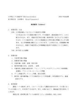
LNAPL Transmissivity Application and Estimation Andrew Kirkman P.E. 1 Outline LNAPL Transmissivity Overview LNAPL Transmissivity Endpoints Baildown Tests Introduction to LNAPL Transmissivity 05/19/2014 2 Why use LNAPL transmissivity? •LNAPL Thickness − Inconsistent between hydraulic scenarios (perched, confined, unconfined) − Inconsistent between soil types − Poor indicator of LNAPL recovery •LNAPL Recovery Rate More Robust Metric than LNAPL Thickness − Need recovery system or pilot test data − Operational variability and technology differences make it difficult to use across technologies and/or sites •Transmissivity − Estimated with recovery data or field testing on monitoring wells − Consistent across soil types − Consistent across confined, unconfined or perched conditions Introduction to LNAPL Transmissivity 05/19/2014 3 LNAPL Transmissivity • LNAPL transmissivity summarizes the following key considerations in LNAPL recovery into one metric: Well − LNAPL density − LNAPL viscosity To = ∑Ko ∆bo LNAPL − Soil permeability − Magnitude of LNAPL saturation in soil (i.e., LNAPL concentration) − Thickness that LNAPL flows over ρ o ⋅ g ⋅ k ⋅ k ro Ko = µo Water Introduction to LNAPL Transmissivity 05/19/2014 4 How Transmissivity Relates to Reduction of Mobile LNAPL Permeability K2<K1K1>0 A Pipe Zero = Permeability Max Permeability As LNAPL is recovered the number of pores occupied by LNAPL decreases, which in turn decreases its relative permeability. This is reflected in a decrease in LNAPL Transmissivity Introduction to LNAPL Transmissivity 05/19/2014 5 Time Required to Recover LNAPL to Equilibrium Thickness • MW-4 Confined recovers to 5 feet thickness fast than wells 33 feet of starting thickness • MW-18 expected to take 3 years to recover to ~35 ft of thickness MW-1 2008 MW-4 2004 UNCONFINED MW-18 2007 with MW-4 2008 CONFINED MW-6 2008 RECOVERED LNAPL THICKNESS (FT) 35.0 30.0 25.0 20.0 15.0 10.0 5.0 0.0 1 10 100 1000 ELAPSED TIME (MIN) 10000 100000 ~ 2 weeks Introduction to LNAPL Transmissivity 1000000 05/19/2014 6 Gauged LNAPL Thickness Versus Recovery - Poor Correlation WATER ENHANCED RECOVERY AT 1 FOOT OF DRAWDOWN (GPD) LNAPL SKIMMING RATE (GPD) GAUGED LNAPL THICKNESS (FT) LNAPL RECOVERY METRIC VALUE 1000 100 33.00 33.15 10 19.03 5.40 2.60 1 0.1 0.01 MW-18 MW-6 MW-4 CONFINED MW-4 UNCONFINED MW-1 Introduction to LNAPL Transmissivity 05/19/2014 7 LNAPL Transmissivity Versus Recovery Good Correlation • LNAPL transmissivity exhibits improved correlation • LNAPL recovery rate is a function of both drawdown induced and LNAPL transmissivity LNAPL RECOVERY METRIC VALUE • Skimming drawdown is controlled by equilibrium fluid levels and soil profile 2πTs Q= ln( Roi / rw ) WATER ENHANCED RECOVERY AT 1 FOOT OF DRAWDOWN (GPD) LNAPL SKIMMING RATE (GPD) LNAPL TRANSMISIVITY (FT2/DAY) 1000 100 35 10 31 5.2 1 0.1 0.22 0.01 0.007 0.001 MW-18 MW-6 MW-4 CONFINED MW-4 UNCONFINED MW-1 Introduction to LNAPL Transmissivity 05/19/2014 8 LNAPL Transmissivity versus Gauged LNAPL Thickness – Poor Correlation • Data from multiple sites “Scatter” LNAPL TRANSMISSIVITY (FT2/DAY) • LNAPL thickness for a given impact depends on hydrogeologic scenario, soil type, variability in water table 100 10 1 0.1 0.01 0.001 0.0001 0 1 10 GAUGED LNAPL THICKNESS (FT) Introduction to LNAPL Transmissivity 100 05/19/2014 9 Industry Efforts to Further LNAPL Understanding • 2006 ASTM Guide of LNAPL Conceptual Site Models • 2009 ITRC Guide for LNAPL technology selection – includes LNAPL transmissivity range 0.1 to 0.8 ft2/day that corresponds to closed sites in various states • 2011 ASTM Guide for Estimation of LNAPL Transmissivity • API multiple tools and documents – most pertinent here LNAPL baildown test spreadsheet and guide document − Now Available − search for LNAPL transmissivity on API.org Introduction to LNAPL Transmissivity 05/19/2014 10 Goals of Standard • Increase accuracy of calculations for LNAPL transmissivity • Provide standardization to generate a consistent and larger database of information • Identify critical assumptions and best practices • Many points are similar in recent guidance and historical such as the importance of well development • Include multiple methods in a single standard to provide comparison of methods • Methods include: 1. Baildown/Slug Tests (Huntley, 2000) 3. Manual Skimming Tests 2. Recovery System Data (Charbeneau, 2007) 4. Tracer Tests (Sale, 2007) Introduction to LNAPL Transmissivity 05/19/2014 11 ASTM Methods; Which One • Baildown Testing − Gauged LNAPL thicknesses >0.5 ft − Requires equilibrium fluid levels • Manual Skimming Tests − No thickness limitation − Requires equilibrium fluid levels Initial Site Characterization Recovery System Evaluation Small Radius of Influence • Tracer Testing − Equilibrium fluid levels − LNAPL gradient • Recovery System Data − Accurate measurements of oil, water and/or air flows − Aquifer properties – hydraulic conductivity saturated and potentially vadose zone; hydraulic gradient − Large radius of influence Introduction to LNAPL Transmissivity 05/19/2014 12 So What Transmissivity Value Means there’s a Bunch of LNAPL There • New catastrophic release scenario’s have resulted in LNAPL transmissivity values on the order of 80 ft2/day • Consider the Theim Equation: 𝑄= 2𝜋𝜋𝜋 𝑅 ln (𝑟 ) e • 80 ft2/day with skimming (~1 ft of drawdown) would result in 816 gpd − Or recover 80% of a 700K gallon release in 2 years with 6 skimming wells that exhibited declining recovery • LNAPL transmissivity of 0.1 skimming (~ 0.15 ft of drawdown) would result in < 0.2 gpd − Or recover 300 gallons in 4 years − Total remaining plume size is < 6400 gallons − Hydraulic recovery no longer effective in significant plume reduction Introduction to LNAPL Transmissivity 05/19/2014 13 LNAPL Transmissivity in Practice Skimming LNAPL at 0.1 ft2/day results in less than 400 GPY skimming • Skimming LNAPL at 5 ft2/day results in 7300 GPY skimming 0.01 1000 3.7E+05 100 3.7E+04 10 3.7E+03 1 3.7E+02 LNAPL RECOVERY RATE (GPD) • 0.1 5 10 20 LNAPL TRANSMISSIVITY CURVES 0.1 3.7E+01 MULTI-PHASE & VACUUM SKIMMING WATER ENHANCED ENHANCED RANGE SKIMMING RANGE RECOVERY Example Technology Drawdown Ranges 0.01 0.1 1 LNAPL DRAWDOWN (FT) Introduction to LNAPL Transmissivity LNAPL RECOVERY RATE (GPY) 1 3.7E+00 10 05/19/2014 14 Stop Metric Example Introduction to LNAPL Transmissivity 05/19/2014 15 What Fraction Can Be Removed for a Given Starting LNAPL Transmissivity Introduction to LNAPL Transmissivity 05/19/2014 16 f -factor – Residual saturation • Residual saturation is proportional to the maximum historical saturation • As LNAPL saturation goes up so does the amount left behind BUT • The residual fraction is constant relative to the maximum historical saturation 𝑆𝑛𝑛 = 𝑓𝑓max General Rules of Thumb for f-factors Clean Sands – 0.2 Silts – 0.3 Clays – 0.4 Johnston, C. and Adamski, M. 2005 • So 30% of what is released to a silt becomes residual Introduction to LNAPL Transmissivity 05/19/2014 17 Decline Curve Analysis • As volume is recovered the saturation is decreased thereby decreasing the rate at which it can be recovered for a given drawdown • No more volume can be recovered as Tn goes to Zero GROUP OF WELLS LNAPL TRANSMISSIVITY (FT2/DAY) 16 Tn= -3.49E-05Vmobile + 2.50E+01 14 12 10 8 Solve for Vmobile at Tn=0 6 Tn − 2.50E+01 =Vmobile −3.49E−05 4 2 0 0 100,000 716,000 𝑔𝑔𝑔=Vmobile 200,000 300,000 400,000 500,000 CUMULATIVE RECOVERED LNAPL (GAL) 600,000 700,000 Introduction to LNAPL Transmissivity 800,000 05/19/2014Page 18 Using Decline Curve Analysis with f -factor to Estimate Residual LNAPL • 𝑆𝑛𝑛 = 𝑓𝑓𝑡𝑡𝑡𝑡𝑡 • 𝑆𝑡𝑡𝑡𝑡𝑡 = 𝑆𝑛𝑛 +𝑆𝑚𝑜𝑜𝑜𝑜𝑜 • 𝑆𝑛𝑛 𝑓 = 𝑆𝑛𝑛 +𝑆𝑚𝑚𝑚𝑚𝑚𝑚 • 𝑆𝑛𝑛 = 𝑓𝑆𝑚𝑚𝑚𝑚𝑚𝑚 1−𝑓 or 𝑉𝑛𝑛 = • Decline Curve Yields 𝑉𝑚𝑚𝑚𝑚𝑚𝑚 𝑓𝑉𝑚𝑚𝑚𝑚𝑚𝑚 1−𝑓 • 𝑉𝑛𝑛 = ∬ 𝑆𝑛𝑛 d𝑏𝑏𝑏 = ∬ 𝑓𝑓𝑡𝑡𝑡𝑡𝑡 d𝑏𝑏𝑏 = ∬ 𝑓𝑆𝑚𝑚𝑚𝑚𝑚𝑚 d𝑏𝑏𝑏 1−𝑓 Introduction to LNAPL Transmissivity 05/19/2014 19 Reversed Decline LNAPL Transmissivity 100% 17 90% 15 80% 13 70% 60% LNAPL Recovered After Reaching 0.6 ft2/day 50% 40% LNAPL Recovered Above LNAPL Transmissivity of 0.6 ft2/day 9 7 5 Remaining Volume Above Residual 30% 11 3 1 20% 10% -1 RESIDUAL VOLUME 0% 0.0 1.0 2.0 3.0 ELPASED TIME (YEARS) 4.0 Introduction to LNAPL Transmissivity LNAPL TRANSMISSIVITY (FT2/DAY) REMAINING VOLUME (GAL) Remaining Volume In Place -3 5.0 05/19/2014 20 Fraction Recovered versus LNAPL Transmissivity – Empirical Data Residual LNAPL Fraction (unrecoverable) >10 years - Elapsed Time Fraction of LNAPL Beyond Proposed Endpoint Range/was not Recovered FRACTION OF TOTAL LNAPL WITHIN MOBILE INTERVAL PRIOR TO RECOVERY EFFORTS (%) 100% Fraction of LNAPL Beyond Proposed Recovery Endpoint/Continued to be Recovered with Significant Effort Residual Fraction 90% 80% 2 years 0.6 years 0.6 years 70% 60% Mobile Fraction Not Recovered 50% 40% 30% 2 years 8 years 6 years 3.75 years 10% 12 years 13.5 years 11 years 2 years 20% 8 years 11 years Recovery Time and Fraction Beyond Endpoint 8 years 14 years Time Until Transmissivity 11 years 2 2 of 7.5 years 0.6 ft /day (0.55 m /day) 0% 14 Well 7 14 Wells 8 - 21 Site 1 6 Well 22 2 Well 1 3.6 Well 2 10Starting1.4 4.6 1.4 LNAPL Transmissivity Well 3 Well 4 Site 2 Well 5 Well 6 4 years >50 years 10 years 2/day) (ft0.0015 0.35 Wells 23 24 Well 25 Site 3 Site 4 0.0023 Introduction to LNAPL Transmissivity 05/19/2014 21 LNAPL Transmissivity – Stop/Start Metric Residual LNAPL Fraction (unrecoverable) Fraction of LNAPL Beyond Proposed Endpoint Range/was not Recovered >10 years - Elapsed Time Fraction of LNAPL Beyond Proposed Recovery Endpoint/Continued to be Recovered with Significant Effort >10 years - Estimated Time Fraction of LNAPL Within Proposed Endpoint Range FRACTION OF TOTAL LNAPL WITHIN MOBILE INTERVAL PRIOR TO RECOVERY EFFORTS (%) 100% 90% 80% 2 years 0.6 years 0.6 years 70% 10 years 60% 8 years 50% 12 years 13.5 years 40% 30% 8 years 2 years 11 years >10 years 2 years 20% 6 years 3.75 years 10% 11 years 8 years 14 years 7.5 years 11 years 4 years >50 years 10 years 0% 14 14 6 2 3.6 10 1.4 4.6 1.4 0.0015 0.0023 0.35 Well 5 Well 6 Wells 23 24 Well 25 Site 3 Site 4 INITIAL LNAPL TRANSMISSIVITY (FT2/DAY) Well 7 Wells 8 - 21 Well 22 Well 1 Site 1 Well 2 Well 3 Well 4 Site 2 NOTES: 1. RECOVERABLE LNAPL VOLUMES ARE BASED ON DECLINE CURVE ANALYSIS, MASS BALANCE AND MODEL CALIBRATION 2. RESIDUAL SATURATIONS ARE BASED ON SOIL CORE ANALYSES AND/OR MODEL CALIBRATION TO FIELD DATA 3. MODEL CALIBRATION INCLUDED, SOIL AND FLUID TYPE, AND LNAPL TRANSMISSIVITY DATA Introduction to LNAPL Transmissivity 05/19/2014 22 How Do We Generate This Information for Retail Sites • Run the API LNAPL Distribution and Recovery Model (Start/Stop Metric) − Residual saturation, use TPH data across smear zone or f-factor − LNAPL transmissivity − Fluid gauging − Soil hydraulic conductivity − Viscosity, more for complex LNAPL mixtures, crude oils • Decline Curve Analysis (Stop Metric) − Requires longer-term recovery data that conforms to decline behavior − F-factor or other residual estimate (e.g., TPH) • Both are conservative and only include mobile interval from start of data/time period considered Introduction to LNAPL Transmissivity 05/19/2014 23 LNAPL Transmissivity used to define extent of recovery system Large Warehouse 32 FT RADIUS LNAPL exists in well casing interval only and is no longer recharging to well Tn = Transmissivity ft2/day LNAPL = Thickness ft Tn 0.10 LNAPL 13.22 Tn 3.4 LNAPL 11.42 Tn 2.8 to 8.6 LNAPL 11.43 AOS/217-D LNAPL 0 LNAPL 0 LNAPL 0 Tn 0.10 LNAPL 3.01 LNAPL 0 LNAPL 0 Tn 2.7 to 8.3 LNAPL 13.59 Tn 3.2 LNAPL 11.44 LNAPL 8.48 Tn 3.4 LNAPL 13.69 LNAPL 0 Tn 0.003 LNAPL 0.35 Tn 0.16 LNAPL 13.1 Introduction to LNAPL Transmissivity 05/19/2014 24 Remedial Performance Application - Scenario 1 • Strong decline indicates recovery system is well representative of capture zone Graphics provided by Introduction to LNAPL Transmissivity 05/19/2014 25 Remedial Performance Application - Scenario 2 • Weak decline supports using individual well measurements (e.g., baildown tests) to measure LNAPL transmissivity across the plume Graphics provided by Introduction to LNAPL Transmissivity 05/19/2014 26 Baildown Tests • Applicable to: − Aquifer types: confined, unconfined, perched − Developed monitoring well Qn Vn • Test method: − Remove borehole LNAPL (i.e. well plus sand pack) Vadose LNAPL Groundwater Filter Pack sn bn rw Well radius – adjusted for filter pack porosity and NAPL saturation − Monitor LNAPL layer recovery • Analytical options: − Cooper-Jacob Method − Bouwer-Rice Methodology • Not generally applicable to − LNAPL thicknesses <0.5 feet − Variable water-table conditions where recharge is long compared to changes in groundwater elevation. Introduction to LNAPL Transmissivity 05/19/2014 27 Move to Baildown Test Example #1 Introduction to LNAPL Transmissivity 05/19/2014 28 Baildown Test Example #1 • Results: − Initial test required adjustment of equilibrium fluid levels based on recovery trend − Revised analysis resulted in LNAPL Transmissivity values ranging by a factor of 2 A retest would likely provide higher certainty but results exhibit a reasonable variability • Thoughts: − Based on the reference range of 0.1 to 0.8 ft2/day ( ITRC, 2009) there is a good chance that recovery at this location will be effective − Small variability in results will not likely change remedial decisions, order of magnitudes can change remedial decisions − Recovery system performance data can then be used to further evaluate the magnitude of LNAPL Tn with appropriate design considerations − These include LNAPL volume over time & system performance parameters can be measured (i.e., water extraction rate, air flow, applied vacuum, pump/stinger depth) − B-R is sensitive to the term ln(Roi/re) for baildown tests (e.g., values of 10 versus 3.9) • However, it is a good idea to retest this well with manual skimming test or a second baildown test if this level of accuracy is insufficient, e.g.: − Look at well spacing and drawdown versus time to remediate Introduction to LNAPL Transmissivity 05/19/2014 29 API Baildown Spreadsheet − Helps identify and eliminate borehole recharge − Includes methodology to analyze constant discharge portions of confined and perched tests − Includes multiple graphs for data interpretation Generalized Bouwer and Rice (1976) r ln (R re ) ln (s n (t1 ) s n (t )) Tn = e 2 (− J )(t − t1 ) 2 Enter early time cut-off for least-squares model fit Timecut 0 Le/re 6.8 <- Enter or change value here Model Results: Tn (ft2/d) = 5.07 +/- 0.13 C 1.07 R/re ft2/d 0 100 200 300 3.95 J-Ratio Time (minutes) -0.157 400 500 0.0 -0.5 -1.0 • Analysis Methods -1.5 − Bouwer-Rice -2.0 -2.5 − Cooper-Jacob -3.0 − CP&B -4.0 -3.5 Natural Log of Drawdown (ft) • Provides tool consistent with ASTM methodology to analyze baildown tests Coef. Of Variation 0.02 Bouwer and Rice Model C coefficient calculated from Eq. 6.5(c) of Butler, The Design, Performance, and Analysis of Slug Tests, CRC Press, 2000. Introduction to LNAPL Transmissivity 05/19/2014 30 Input Parameters for Baildown Tests • Input Parameters and initial considerations provide basis for analysis decisions and affect accuracy of the analysis • LNAPL Density − Although the variation in density (ρr) between 0.75 g/cc and 0.9 g/cc seems small ~ 20% − LNAPL drawdown calculations use (1-ρr) which results in up to 127% variation in drawdown and therefore LNAPL Transmissivity estimates. Introduction to LNAPL Transmissivity 05/19/2014 31 Effective Well Radius • Well casing and filter pack radius − Discharge is proportional to the square of the effective well radius − Discharge is 65% higher for a 4-inch well in 8.25 inch borehole versus a 2-inch well in an 8.25 inch borehole and 5% higher for a 8.25 –inch borehole versus an 8-inch borehole − Many historical wells do not have borehole diameter well documented C&J Method B&R Method Calculated LNAPL Volume (gal) Correct Borehole Borehole Error -25% Correct 25% Le/re 36.4 28.9 24.7 R/re 15.2 12.6 11.1 Transmissivity (ft2/day) 0.5 0.8 1 r ln(R re ) ln(sn (t1 ) sn (t )) Tn = e 2 (− J )(t − t1 ) +25% Borehole Error -25% Borehole Error 3.5 3.0 2.5 2.0 1.5 4πTn s j i Vn (ti ) = ∑ 1.0 j 0.5 2.25Tn t j ln 2 re S n ∆t j 0.0 2 0.0 Used with Permission from T. Andrews 1.0 2.0 3.0 4.0 Measured LNAPL Volume (gal) Introduction to LNAPL Transmissivity 5.0 05/19/2014 32 Filter pack volume • Filter pack holds 67% of the LNAPL for a 2-inch well within an 8.25 inch borehole • Removing casing volume only results in inducing less drawdown and having to filter out borehole recharge behavior from test Filter Pack Static Fluid Levels Well Casing/Screen Aerial View of Well Static fluid level conditions LNAPL removed Following borehole from well casing recharge prior to formation recharge only Introduction to LNAPL Transmissivity 05/19/2014 33 Considering Well Geometry Effects • Submerged screens where LNAPL recovers over the top of screen presents a special condition particularly for fluctuating water tables Exposed Screen Submerged Casing Screen Recharge • LNAPL discharge and LNAPL Transmissivity are highly sensitive to effective well radius V πr ∆b Qn = n = e n ∆t ∆t 2 i Vn (ti ) = ∑ j Vn1 = Vn2 = Vn3 4πTn s j 2.25Tn t j ln 2 re S n ∆t j r ln(R re ) ln(sn (t1 ) sn (t )) Tn = e 2 (− J )(t − t1 ) 2 Occur with Confined LNAPL Introduction to LNAPL Transmissivity 05/19/2014 34 Well Construction • Well screens need to extend over the entire LNAPL mobile interval Well 1 Well 2 • • Well 1 will exhibit larger Tn than Well 2 because saturation is variable across mobile interval Well LNAPL LNAPL saturation and relative permeability peak at air/LNAPL interface for unconfined homogenous conditions Water Introduction to LNAPL Transmissivity 05/19/2014 35 Equilibrium Conditions Transmissivity Analysis 36 Key Points for Conducting & Analyzing Baildown Tests − Understanding equilibrium fluid levels ensures accurate calculation of LNAPL drawdown − Establish that in-well LNAPL thicknesses are at equilibrium: pre test monitoring via hydrograph − Gauge well to completion of the test not 80% − May not be feasible at site where baildown tests require weeks or months to recover − Discharge versus drawdown plots derived from baildown test data can potentially be used to supplement where equilibrium fluid levels are not well understood • Well Development: establishes good communication between well and formation Introduction to LNAPL Transmissivity 05/19/2014 37 Equilibrium Fluid Levels • Manual removal of LNAPL is routinely conducted on wells exhibiting gauged LNAPL thickness at sites − Wells are gauged during monitoring events then purged with fluid levels and volumes removed reported in routine reports − Little understanding accompanies these data with regards to was the LNAPL in equilibrium. • How long does it take a well to equilibrate MW-1 2008 MW-18 2007 MW-4 2004 UNCONFINED MW-4 2008 CONFINED RECOVERED LNAPL THICKNESS (FT) 35 30 25 20 15 10 5 0 1 10 100 1,000 10,000 100,000 1,000,000 ELAPSED TIME (MIN) Introduction to LNAPL Transmissivity 05/19/2014 38 Using Baildown tests to Evaluate Equilibrium Conditions • These plots look pretty good • Is the test complete? 0.80 0.60 0.50 0.10 Time period between 5 PM and 8 AM 0.40 0.30 0.20 0.10 0.00 0 200 400 600 800 1,000 1,200 Time (min) • Operating facilities often present accessibility in terms of timing e.g., refineries and Railroads LNAPL Well Inflow Volume (gal) LNAPL Thickness bn (ft) 0.70 0.09 0.08 0.07 0.06 0.05 0.04 0.03 0.02 0.01 0.00 0 200 400 600 800 1,000 1,200 Time (min) Introduction to LNAPL Transmissivity 05/19/2014 39 Using Baildown tests to Evaluate Equilibrium Conditions • They are more clear when they are in semi-log form 0.80 0.70 0.60 0.50 0.40 0.30 0.20 0.10 0.00 1 10 100 Time (min) 1,000 LNAPL Well Inflow Volume (gal) LNAPL Thickness bn (ft) − These indicate additional gauging is needed 0.10 0.09 0.08 0.07 0.06 0.05 0.04 0.03 0.02 0.01 0.00 1 10 100 1,000 Time (min) • These plots can be used where equilibrium is not be known or to confirm equilibrium fluid levels • Confirming is a recommended practice - ASTM Introduction to LNAPL Transmissivity 05/19/2014 40 Using Baildown tests to Evaluate Equilibrium Conditions Gauged LNAPL Thickness (feet) • In addition to baildown test data Hydrographs can be used in a similar fashion AIR/LNAPL INTERFACE (FT MSL) LNAPL/WATER INTERFACE(FT MSL) CORRECTED GROUNDWATER ELEVATION (FT MSL) WELL SCREEN Fine Grained Sand 49 -11 -21 12 10 8 6 4 2 0 10 100 1000 Time Elapsed Since Last Removal (Days) 10000 DEPTH (FT BGS) ELEVATION (FT MSL) -1 14 1 29 9 16 69 -31 -41 -51 10/10/06 2/22/08 7/6/09 DATE 11/18/10 89 4/1/12 Introduction to LNAPL Transmissivity 05/19/2014 41 Thank you Andrew Kirkman, P.E.
© Copyright 2026 ExpyDoc