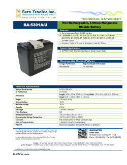
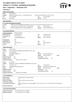
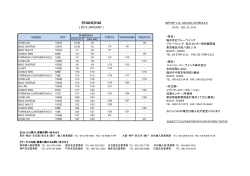
IWAKI
MAGNETIC
DRIVE
PUMPS
MXM
Patent
JAPAN / U.S.A. / TAIWAN / EU / CHINA
Better withstanding difficult operating conditions
The proven non-contact system and self-radiating bearing structure deliver substantial improvements in tolerance of dry running and poor suction conditions.
Non contact system
Unlike conventional magnetic drive
pumps, the MXM series are designed to
prevent contact between the bearing
and the rear thrust faces, even during dry
running. By preventing contact, the rear
thrust ring minimizes heat generation to
prevent melting of plastic parts.
Abnormal operation
Normal operation
Spindle
Self radiation structure (PAT.)
Through heat-dispersion holes provided
in the fixed portions of the impeller and
the magnet capsule, the liquid around
the spindle and the bearing is forced to
circulate so that heat generated by sliding
can be reduced effectively. Thus, thermal
deformation and melt are prevented.
1
Rear thrust
Heat-dispersion holes
Bearing
IWAKI MAGNETIC DRIVE PUMPS
MXM
Magnetic drive pumps with an excellent balance
of features and performance
The MXM series of pumps have now been added to the line-up of Iwaki’s magnetic drive process pumps, which have
earned high acclaim and the trust of users all around the world. The new MXM series feature an excellent balance of
the characteristics required of chemical pumps, including corrosion resistance, durability and safety. They employ
a non-contact, self-radiating bearing structure to better withstand difficult operating conditions. The advent of the
MXM series has further expanded the array of choices offered by Iwaki’s process magnetic drive pumps.
Exceptional corrosion resistance
Robust structure
Enhanced safety
The MXM series employ optimum anticorrosive materials such as carbon fiber
reinforced ETFE (CFRETFE), high quality
ceramic and carbon for parts that come
in contact with liquid. The most suitable
impeller size and
motor output can
be selected for the
required liquid property.
The pumps have an external armour of
high strength ductile cast iron for use
in heavy duty chemical process applications.The sealing performance between
the front casing and the rear casing is
drastically enhanced by our original
structure (patent pending), offering high
reliability.
The MXM features a unique rear casing
shape designed to prevent stress concentration. This increases both the pump’s
pressure resistance and the mechanical
strength of the spindle support. The high
temperature model uses a dual structure
incorporating an FRP rear casing cover. In
addition to further increasing the pump’s
pressure resistance, it improves safety
with dual containment preventing liquid
leakage in the event of unexpected damage to the rear casing.
Impeller+Magnet capsule
Cover+Front casing
Spindle+Bearing
Rear casing+Rear casing cover
(Option)
MXM545
MXM542
2
Construction and materials
2 Rear casing
Material code
CF
Part
FF
KK
4 Magnet capsule
1 Front casing
2 Rear casing
CFRETFE
3 Impeller
11 Lock pin
4 Magnet capsule
5 Spindle
5 Spindle
High-purity alumina ceramic
High-density
carbon
6 Bearing
7 Liner ring
High-purity
alumina ceramic
SiC
1 Front casing
7 Liner ring
High-purity alumina ceramic
8 Mouth ring
PTFE with filler
9 Rear thrust
MXM22/44: CFRETFE, MXM54: CFRPFA
10 O ring
11 Lock pin
3 Impeller
FKM/EPDM/AFLAS®/ DAI-EL PERFLUORO®
Note
CFRETFE
Note: 54 type only
8 Mouth ring
6 Bearing
9 Rear thrust
10 O ring
Specifications (50Hz)
Model
MXM22 (Impeller range 1)
Pump size
Suction × Discharge
25mm × 25mm
MXM22 (Impeller range 2)
MXM44 (Impeller range 1)
40mm × 40mm
MXM44 (Impeller range 2)
MXM54 (Impeller range 1)
MXM54 (Impeller range 3)
MXM54 (Impeller range 4)
50mm × 40mm
Impeller
size
Capacity
L/min
Head
m
100
090
070
105
115
110
100
090
130
150
140
120
150
140
130
110
150
140
125
110
150
150
150
150
200
200
200
200
200
200
200
200
300
300
300
300
400
400
400
400
7.5
5.5
2.5
8
9.5
8
6
5
12
18.5
17
13.5
20
18.5
16.5
10.5
25
20.5
15.5
9.5
Note1: Liquid temp. range
Standard: -10 to 90 °C High temp. version (with rear casing cover): -10 to 105 °C (10 to 105 °C when AFLAS® O ring is used)
Note2: Max operating pressure
Standard MXM22: 0.2MPa, MXM44: 0.3MPa, MXM54: 0.45MPa High temp. version (with rear casing cover): 0.7MPa
3
IWAKI MAGNETIC DRIVE PUMPS
MXM
Pump identification
MXM 54 2 - 150 1 E CF V J - H
Series symbol
MXM
Pump size (Suction × Discharge)
22 : 25mm × 25mm
44 : 40mm × 40mm
54 : 50mm × 40mm
Motor output
0 : 0.4kW
1 : 0.75kW
2 : 1.5kW
3 : 2.2kW
5 : 4.0kW
Impeller size
150, 140, 130, 125, 120, 115, 110
105, 100, 095, 090, 085, 080, 075, 070
Special code
H : High temperature version
(with rear casing cover)
B : With base plate
S : Other special order
*Special code may overlap.
Main material
E : CFRETFE
Impeller range
1 or 2: MXM22
1 or 2: MXM44
1, 3 or 2: MXM54
Material of Bearing / Spindle
CF : High density carbon / High purity alumina ceramic
FF : High purity alumina ceramic / High purity alumina ceramic
KK : SiC/SiC
Standard for pipe connection and motor
J : JIS flange + JIS motor
I : ISO flange + IEC motor
A : ANSI flange + JIS motor
U : ANSI flange + NEMA motor
Material of O ring
V : FKM
E : EPDM
A : AFLAS®
P : DAI-EL PERFLUORO®
Notes for selection
(1) The performance curves in this catalogue represent the data measured using clear water at 20 °C.
(2) Choose the pump model suited to the liquid gravity.
Make sure that the motor output is at least five to ten percect higher than theoretically required.
Shaft power (Sp) × liquid gravity × 1.1 < Motor output
(Note) The shaft power (Sp) increases in proportion to the liquid gravity.
As the viscosity rises, the shaft power is higher while the head and the discharge are lower.
The power and the performance need to be adjusted.
(3) No magnetic drive pump supports continuous closed running. Be sure to ensure the mininum flow volume.
• Minimum flow volume
MXM22/44
: 10 L/min.
MXM54 Impeller range 1, 2 and 3 : 20 L/min.
Impeller range 4
: 50 L/min.
(4) The pressure resistance of the pump is as follows.
Be sure to ensure that the internal pressure of the pump does not exceed the value specified below.
• Standard model -10 °C to 90 °C (without rear casing cover)
MXM22: 0.2MPa, MXM44: 0.3MPa, MXM54: 0.45MPa
• High temperature version -10 °C to 105 °C (with rear casing cover)
: 0.7MPa
(5) FF material models
• Liquid should be 1m Pa·s (cP) or more.
• HQ performance is somewhat different from CF/KK models.If you need to know the detail, please contact with us.
(6) Deliberate prolonged dry running or entrained air operation is not recommended.
• The CF type has a degree of tolerance to dry running and operation with entrained air in the liquid.
• The KK type has the same degree of tolerance as the CF type under operation with entrained air in the liquid, but not allowed to run dry.
• The FF type is not allowed to run dry or operation with entrained air.
4
Performance curves
Sp
22-1052
0.5
22-1001
0.4
22-0901
0.3
22-0701
0.2
15
MXM44
50Hz
Sp
44-0901
20
H-Q
44-1151
HEAD (m)
HEAD (m)
0.2
15
22-0701
0.4
44-1302
22-1001
22-0901
0.6
44-1001
H-Q
10
0.8
44-1101
44-1151
0.1
22-1052
1.0
44-1302
44-1101
44-1001
44-0901
10
SHAFT POWER (kW)
50Hz
SHAFT POWER (kW)
MXM22
5
5
0
50
100
150
200
0
250
0
100
CAPACITY (L/min)
MXM54 Performance curves
MXM54 (Impeller range 1)
50Hz
54-1503
300
4.0
50Hz
54-1501
3.0
54-1403
54-1404
54-1504
Sp
2.0
54-1501
54-1401
54-1201
20
HEAD (m)
54-1401
1.0
30
0.0
54-1254
10
54-1501
HEAD (m)
54-1201
H-Q
20
54-1303
54-1104
54-1401
10
54-1103
54-1201
0
0
0
100
200
300
400
500
600
0
100
200
CAPACITY (L/min)
MXM54 (Impeller range 3)
54-1503
2.0
54-1403
54-1303
54-1103
1.0
30
600
54-1504
Sp
54-1404
3.0
54-1254
54-1104
2.0
1.0
54-1504
30
0.0
0.0
H-Q
54-1404
H-Q
HEAD (m)
54-1403
54-1303
10
54-1254
20
54-1503
HEAD (m)
500
4.0
50Hz
SHAFT POWER (kW)
3.0
20
400
MXM54 (Impeller range 4)
4.0
50Hz
Sp
300
CAPACITY (L/min)
54-1104
10
54-1103
0
0
100
200
300
400
500
600
0
CAPACITY (L/min)
· The shaft power curves shown above are calculated by using our standard test motor. Contact us for detail.
5
0
100
200
300
CAPACITY (L/min)
400
500
600
SHAFT POWER (kW)
30
200
CAPACITY (L/min)
SHAFT POWER (kW)
0
IWAKI MAGNETIC DRIVE PUMPS
MXM
Dimensions in mm
(L)
c
c
A
h
B
f
f
(H)
(H)
g
B
(L)
With base
h
A
g
Without base
a
(b)
i
(d)
e
d
i
a
e
j
(W)
Without base
Model
MXM220
MXM220-H
MXM221
MXM221-H
MXM441
MXM441-H
MXM442
MXM442-H
MXM542
MXM543
MXM545
With base
Model
MXM220
MXM220-H
MXM221
MXM221-H
MXM441
MXM441-H
MXM442
MXM442-H
MXM542
MXM543
MXM545
(H)
237
(L)
453
475
A
B
a
(b)
c
(d)
25A
25A
110
150
51
95
275
40A
40A
130
170
58
113
40A
50A
140
180
65
106
g
h
i
115
122
88
4-ø12
250
135
140
106
4-ø14
275
155
140
87
4-ø14
165
467
482
495
f
e
143
537
295
517
589
(W)
(H)
300
317
(L)
453
475
A
B
a
c
d
e
f
g
h
i
j
25A
25A
250
51
130
220
195
122
88
4-ø19
450
40A
40A
300
58
130
260
225
140
106
4-ø19
489
40A
50A
350
65
140
480
245
140
87
4-ø19
735
467
350
365
482
495
537
400
385
517
589
6
IWAKI MAGNETIC DRIVE PUMPS
MXM
Optional accessories
Iwaki dry running protector DR series
Model DR is electric current sensing type dry running protector. It detects the decreased load current (lower limit) to stop the pump when it
runs dry or runs with air sucking in. It can detect over-load, too.
DR-20
Specification
• Current figure to be set is indicated on LCD.
Model
• Both top/bottom figures can be set.
Motor power
Applied motor
Power control
Top:Over-load
Bottom:Dry running, air sucking-in operation, operation with suction side closed
50Hz
DR-10
200 to 240V three phase
380 to 440V three phase
0.4 to 7.5kW
0.75 to 15kW
100 to 240V single phase
V
Input
• Built-in current transformer
Power
• DIN rail mounting
Detective current
Current transformer(CT )
• It is unable to use DR when inverter is employed in the system.
DR-20
100V ±10%single phase
200 to 240V ±10%single phase
3.5W
0.5 to 32.0A
Built-in
Outer dimension in mm
D80 X W153 X H122
Note: The dry run protector can not be used along with inverter.
IWAKI Process Magnetic Drive Pump Series
MDW SERIES
MDE SERIES
The world largest-class
fluoroplastic magnetic drive pump
The most reliable,
large-sized magnetic drive pump
designed for process use
Specifications
Specifications
• Max.discharge capacity: 300 m /hr
• Max.head: 98 m
• Main materials: ETFE, PFA
• Liquid temp. range: -10 to 105 ºC(ETFE)
-10 to 120 ºC(PFA)
• Max.discharge capacity: 240 m3/hr
• Max.head: 55 m
• Main materials: ETFE, PFA
• Liquid temp. range: 0 to 100 ºC
3
MDM SERIES
MX/MX-F SERIES
SMX/SMX-F SERIES
Magnetic drive process pumps
with dry running capability
Withstands difficult operating conditions
and offers high efficiency
Versatile self-priming magnetic drive pump with
enhanced durability under abnormal operation
Specifications
Specifications
Specifications
• Max.discharge capacity: 84 m3/hr
• Max.head: 74 m
• Main materials: CFRETFE, PFA
• Liquid temp. range: -20 to 105 ºC (CFRETFE)
-20 to 150 ºC (PFA)
• Max.discharge capacity: 30.6 m3/hr
• Max.head: 35 m
• Main materials: GFRPP, CFRETFE
• Liquid temp. range: 0 to 80 ºC
• Max.discharge capacity: 26.4 m3/hr
• Max.head: 25.5 m
• Main materials: GFRPP, CFRETFE
• Liquid temp. range: 0 to 80 ºC
w w w. i wa k i p u m p s.j p
6-6 Kanda-Sudacho 2-chome Chiyoda-ku Tokyo 101-8558 Japan TEL : (81)3 3254 2935 FAX : 3 3252 8892
European office
Germany
Holland
Italy
Spain
Belgium
Denmark
Finland
France
Norway
Sweden
Switzerland
U.K.
: IWAKI Europe GmbH
: IWAKI Europe GmbH
: IWAKI Europe GmbH (Netherlands Branch)
: IWAKI Europe GmbH (Italy Branch)
: IWAKI Europe GmbH (Spain Branch)
: IWAKI Belgium N.V.
: IWAKI Nordic A/S
: IWAKI Suomi Oy
: IWAKI France S.A.
: IWAKI Norge AS
: IWAKI Sverige AB
: IWAKI (Schweiz) AG
: IWAKI Pumps (UK) Ltd.
TEL: (49)2154 9254 0
TEL: (49)2154 9254 50
TEL: (31)547 293 160
TEL: (39)0444 371115
TEL: (34)93 37 70 198
TEL: (32)13 67 02 00
TEL: (45)48 24 2345
TEL: (358)9 2745810
TEL: (33)1 69 63 33 70
TEL: (47)23 38 49 00
TEL: (46)8 511 72900
TEL: (41)26 674 93 00
TEL: (44)1743 231363
FAX: 2154 9254 48
FAX: 2154 9254 55
FAX: 547 292 332
FAX: 0444 335350
FAX: 13 67 20 30
FAX: 48 24 2346
FAX: 9 2742715
FAX: 1 64 49 92 73
FAX: 23 38 49 01
FAX: 8 511 72922
FAX: 26 674 93 02
FAX: 1743 366507
The posting and copying from this catalogue without permission is not accepted firmly.
U.S.A.
Argentina
Singapore
Malaysia
Indonesia
Australia
China
Korea
Taiwan
Thailand
Vietnam
: IWAKI America Inc.
: IWAKI America Inc. (Argentina Branch)
: IWAKI Singapore Pte Ltd.
: IWAKIm Sdn. Bhd.
: IWAKI Singapore (Indonesia Branch)
: IWAKI Pumps Australia Pty Ltd.
: IWAKI Pumps Co., Ltd.
: IWAKI Korea Co.,Ltd.
: IWAKI Pumps Taiwan Co., Ltd.
: IWAKI (Thailand) Co.,Ltd.
: IWAKI Pumps Vietnam Co., Ltd.
TEL: (1)508 429 1440
TEL: (54)11 4745 4116
TEL: (65)6316 2028
TEL: (60)3 7803 8807
TEL: (62)21 6906606
TEL: (61)2 9899 2411
TEL: (852)2607 1168
TEL: (82)2 2630 4800
TEL: (886)2 8227 6900
TEL: (66)2 322 2471
TEL: (84)613 933456
FAX: 508 429 1386
FAX: 6316 3221
FAX: 3 7803 4800
FAX: 21 6906612
FAX : 2 9899 2421
FAX: 2607 1000
FAX: 2 2630 4801
FAX: 2 8227 6818
FAX: 2 322 2477
FAX: 613 933399
( )Country codes
Caution for safety use: Before use of pump, read instruction manual carefully to use the product correctly.
Actual pumps may differ from the photos. Specifications and dimensions are subject to change without prior notice. For further details please contact us.
Legal attention related to export.
Our products and/or parts of products fall in the category of goods contained in control list of international regime for export control.
Please be reminded that export license could be required when products are exported due to export control regulations of countries.
CAT-E 0066-05
2013.03.1000.KPN
© Copyright 2026 ExpyDoc