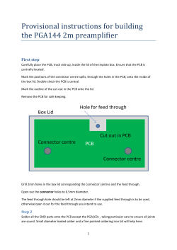
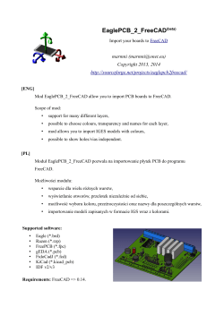
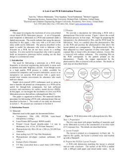
EK57
EK57
EK57 MP108, MP111
Evaluation Kit for MP108FD and MP111FD
INTRODUCTION
This easy-to-use kit provides a platform for the evaluation of
linear power amplifiers circuits using the MP108FD & MP111FD
pin out. With ample bread boarding areas it is flexible enough
to analyze a multitude of standard or proprietary circuit configurations. Critical connections for power supply bypassing
are pre-wired. Components not usually readily available in
engineering labs are provided. External connection to the
evaluation kit can be made via the terminal block and terminal
pads at the edges of the circuit board. The terminal pads are
suitable for soldering standard banana jacks or direct wiring
of wires. Additionally, banana jacks and a BNC connector can
be inserted into the holes at the edge of the board and wired
to the numbered terminal pads.
BEFORE YOU GET STARTED
• All Apex Microtechnology amplifiers should be handled using
proper ESD precautions.
• Do not change connections while the circuit is powered.
• Initially set all power supplies to the minimum operating
voltage allowed in the device data sheet.
• For instructions adapting EK57 for MP118 see EK57 addendum
PARTS LIST
Ref
NA
NA
NA
NA
NA
Apex Part #
HS28
HS31
MS11
EVAL57
60SPG00004
C1,4,5,6 OX7R105KWN
TS1
C2,3
TS02
EC03
RLIM*
CSR18
RLIM*
CSR19
Description/Vendor
Qty
Heat Sink
1
Heat Sink
1
Strip of 30 cage jacks
2
PC Board
1
Spacer Grommets/
4
Micro Plastics
1uF Cap/
4
Novacap
1825B105K201N
Terminal Strip
1
680uF 200V/
2
United Chemi-Con
KMH200VN681M25MX40T2
0.050 Ohm Resistor/
1
Isotek PBV-R050-1
0.100 Ohm Resistor/
1
Isotek PBV-R100-1
ASSEMBLY
During assembly refer to Figure 2 and the data sheet for the
MP108FD & MP111FD.
1. Note that each side of the circuit board is identified as either
the "component side" or "DUT side".
2. Cut the MS11 into groups of 16 and 18 cage jacks and insert
from the "DUT side" of the board. On the "component side"
of the board, solder all cage jacks having solder pads (7, 9,
10, 23, 24, 26, 29, and 31 have no solder pads). Make sure
the cage jacks are fully seated before soldering. Be careful
www.apexanalog.com
EK57U
that solder does not flow into the cage jacks. Remove the
unsoldered cage jacks with the carrier strip segments.
3. Solder the surface mount capacitors at C1, C4, C5, and C6
on the "component side" of the board.
4. Low ohm value resistors are provided with this evaluation
kit: 0.050 ohm and 0.100 ohm. These are used to implement
current limiting in the output circuit. Select the value most
appropriate for your application. Refer to the product data
sheet to determine which resistor value you should use.
5. Mount the HS28 heat sink to the PCB and solder the mounting tabs of the heat sink.
6. Apply a thin layer of thermal grease on the back of the
chosen current limiting sense resistor, insert the resistor
into the PCB and mount the resistor to the HS28 heat sink
using #4 screw and nut hardware (not supplied). Be sure
to cut off the excess resistor lead lengths.
7. Mount the electrolytic capacitors at C2 and C3 from the
"component side" of the PCB. Match the polarity markings
on the capacitor with the polarity markings on the PCB.
Be sure the capacitors have snapped into the PCB and
solder from the "DUT side" of the PCB. Be sure to fill the
holes with solder.
8. Mount the terminal strip to the "component side" of the PCB.
Make sure the terminal strip is fully seated and solder the
pins from the "DUT side" of the PCB. Be sure to fill the
mounting holes with solder.
9. Mount and wire the banana jacks and BNC connector (neither supplied) to the PCB pads at locations 1-5 as needed
or desired.
10. Mount other components to complete your application
circuit using the pads and holes provided.
11. From the "DUT side" of the PCB snap the spacer- grommets into the holes at the four corners of the PCB. Notice
that the holes are slightly rectangular and match the spacergrommet's long and short sides to the holes in the PCB.
12. Apply a thin, uniform layer of thermal grease to the amplifier;
a straight edge may be useful here. Position the amplifier
over the mounting holes in the heatsink. Firmly push the
amplifier onto the heatsink while slightly rotating the amplifier back and forth, ending with the mounting holes of the
amplifier over the mounting holes in the heatsink.
13. Attach the amplifier to the heatsink with 4-40x½’ malefemale hex spacers (not supplied). These spacers serve
as alignment pins and aide in the assembly of the PCB to
the heatsink. Alternatively, use 4-40x¼’ machine screws
to mount the amplifier to the heatsink. Do not over-tighten
the spacers or screws as this provides no thermal benefit
and may break the hardware.
14. Place the PCB assembly on the heatsink/amplifier assembly
so that the hex spacers come through the aligning holes
near the corners of the amplifier location in the PCB. Carefully lower the PCB assembly until the pins of the amplifier
engage the cage jacks. Alternately, sight through the aligning holes in the PCB and match-up the PCB to the screws
used to mount the amplifier. In either case be sure the pins
Copyright © Apex Microtechnology, Inc. 2014
(All Rights Reserved)
SEPT 2014
1
EK57U REVE
EK57
ASSEMBLY CONT.
15. Use #8 X 1" sheet metal screws (not provided) to mount
the PCB to the heat sink at the four spacer-grommets.
16. Inspect the assembly from the side and check that the PCB
is not bowed toward the heat sink. If the PCB is bowed use
a small tool to carefully pry the PCB away from the heat
sink until the PCB is flat.
17. Hook up power and signals as necessary. The amplifier
is now ready for testing.
of the amplifier are engaged with the cage jacks and then
continue pushing the PCB assembly in the area between
the amplifier’s pins until the four spacer grommets at the
four corners of the PCB touch the heatsink. At this point
the PCB should not be bowed.
FIGURE 1: SCHEMATIC DIAGRAM
C1
+
C2
1
C5
TS1
SPARE
2
OUT OUT OUT
1
TP
3
2
4
3
BPLT GND +Vb
12
13
7
8
9
10
14
15
16
CC1 CC2
NC
+Vb
NC
NC
+Vs
+Vs
+Vs
+Ilim -Ilim
NC
-Vb
NC
NC
-Vs
-Vs
-Vs
26
25
24
23
19
18
17
6
5
11
+Vs
+Vb
VIEW FROM PCB COMPONENT SIDE
4
-IN
+IN
GND
NC
-Vb
NC
34
33
32
31
30
29
28
27
22
21
20
GND
OUT OUT OUT
RLIM
5
OUT
-Vs
-Vb
C6
+
C3
C4
PCB AMPLIFIER TERMINALS
PCB WIRING TERMINALS
TERMINAL STRIP TERMINALS
ASSESSORY TERMINALS
2
EK57U
EK57
FIGURE 2:
TOP VIEW
COMPONENT SIDE
MICROTECHNOLOGY
1
+Vs
GND
IC1
SPARE
SPARE
EVAL57 R-A
BANANA
JACK
C2
DUT
ON BOTTOM
+Vb
Cc
16
+Vs
BANANA
JACK
+
+Vb
1
2
BANANA
JACK
C5
OUT
C1
34
Rlim
C4
6.625
REF.
GND
C6
HS28
BANANA
JACK
3
17
5
-Vs
-Vb
GND
OUT
-Vs
-Vb
4
5
+
BNC
INPUT SIG
TS1
GND
C3
9.750
REF.
BOTTOM VIEW
DUT SIDE
EK57U
3
EK57
FIGURE 3:
HS28 HEATSINK
SURFACE MOUNT
CAPACITORS
TERMINAL STRIP
CAGE JACKS
SPACER GROMMET
ELECTROLYTIC CAPACITOR
PC BOARD
NO. 4 MOUNTING HARDWARE
ACCESS HOLES
CURRENT LIMITING SENSE RESISTOR
4-40 x 1/4 SCREWS
DEVICE UNDER TEST (DUT)
ALTERNATE MOUNTING
HARDWARE USING
HEX SPACERS
HS31 HEATSINK
NO. 8 or 10 x 1.0 SHEET METAL SCREWS
NEED TECHNICAL HELP? CONTACT APEX SUPPORT!
For all Apex Microtechnology product questions and inquiries, call toll free 800-546-2739 in North America.
For inquiries via email, please contact [email protected].
International customers can also request support by contacting their local Apex Microtechnology Sales Representative.
To find the one nearest to you, go to www.apexanalog.com
IMPORTANT NOTICE
Apex Microtechnology, Inc. has made every effort to insure the accuracy of the content contained in this document. However, the information is subject to change
without notice and is provided "AS IS" without warranty of any kind (expressed or implied). Apex Microtechnology reserves the right to make changes without further
notice to any specifications or products mentioned herein to improve reliability. This document is the property of Apex Microtechnology and by furnishing this information, Apex Microtechnology grants no license, expressed or implied under any patents, mask work rights, copyrights, trademarks, trade secrets or other intellectual
property rights. Apex Microtechnology owns the copyrights associated with the information contained herein and gives consent for copies to be made of the information only for use within your organization with respect to Apex Microtechnology integrated circuits or other products of Apex Microtechnology. This consent does not
extend to other copying such as copying for general distribution, advertising or promotional purposes, or for creating any work for resale.
APEX MICROTECHNOLOGY PRODUCTS ARE NOT DESIGNED, AUTHORIZED OR WARRANTED TO BE SUITABLE FOR USE IN PRODUCTS USED FOR
LIFE SUPPORT, AUTOMOTIVE SAFETY, SECURITY DEVICES, OR OTHER CRITICAL APPLICATIONS. PRODUCTS IN SUCH APPLICATIONS ARE UNDERSTOOD TO BE FULLY AT THE CUSTOMER OR THE CUSTOMER’S RISK.
Apex Microtechnology, Apex and Apex Precision Power are trademarks of Apex Microtechnolgy, Inc. All other corporate names noted herein may be trademarks
of their respective holders.
www.apexanalog.com
4
Copyright © Apex Microtechnology, Inc. 2014
(All Rights Reserved)
SEPTEK57U
2014
EK57U REVE
© Copyright 2026 ExpyDoc